
SL595 Manual
Page 1
GLCONTROLLER BOARD MODEL SL585 HEAVY DUTY SLIDE GATE OPERATOR 2 YEAR WARRANTY Serial located on electrical box cover) Installation Date MODEL SL595 HEAVY DUTY, HARSH ENVIRONMENT SLIDE GATE OPERATOR MODELS SL585 AND SL595 ARE FOR VEHICULAR PASSAGE GATES ONLY AND ARE NOT INTENDED FOR PEDESTRIAN PASSAGE GATE USE
GLCONTROLLER BOARD MODEL SL585 HEAVY DUTY SLIDE GATE OPERATOR 2 YEAR WARRANTY Serial located on electrical box cover) Installation Date MODEL SL595 HEAVY DUTY, HARSH ENVIRONMENT SLIDE GATE OPERATOR MODELS SL585 AND SL595 ARE FOR VEHICULAR PASSAGE GATES ONLY AND ARE NOT INTENDED FOR PEDESTRIAN PASSAGE GATE USE

SL595 Manual
Page 2
...you to the possibility of damage to your commercial door and gate operator unless you MUST read and fully understand this Signal Word on the AVERT ADJUSTMENT following pages, it . Model SL595 35 Illustrated Parts - TABLE OF CONTENTS OPERATOR SPECIFICATIONS IMPORTANT NOTES ... Power Wiring Installation 8 INSTALWLATAIORN NING Pad Mounting (SL585 only 9 Post Mounting (SL585 & SL595 10 CAUTION Install Gate Bracket and Drive Chain 11 Available Conduit Access for Open Roller Gates 7 Warning Sign Placement 7 • DO NOT attempt repair or service of SERIOUS Limit Switch...
...you to the possibility of damage to your commercial door and gate operator unless you MUST read and fully understand this Signal Word on the AVERT ADJUSTMENT following pages, it . Model SL595 35 Illustrated Parts - TABLE OF CONTENTS OPERATOR SPECIFICATIONS IMPORTANT NOTES ... Power Wiring Installation 8 INSTALWLATAIORN NING Pad Mounting (SL585 only 9 Post Mounting (SL585 & SL595 10 CAUTION Install Gate Bracket and Drive Chain 11 Available Conduit Access for Open Roller Gates 7 Warning Sign Placement 7 • DO NOT attempt repair or service of SERIOUS Limit Switch...

SL595 Manual
Page 3
....8 cm) 14.1" (35.8 cm) 12.9" (32.8 cm) Opposite Gate Side 14.9" (37.9 cm) MODEL SL595 • 1/2 HP Motor Maximum Gate Speed - 12"/sec. (30.5 cm/sec) Maximum Gate Weight - 1100 lbs. (499 kg) Maximum Cantilever Gate Width - 25 ft. (7.6 m) Maximum Overhead Roller Gate Width - 45 ft. (13.7 m) Maximum V-Track Gate Width - 35 ft. (10.7 m) • 1 HP Motor...
....8 cm) 14.1" (35.8 cm) 12.9" (32.8 cm) Opposite Gate Side 14.9" (37.9 cm) MODEL SL595 • 1/2 HP Motor Maximum Gate Speed - 12"/sec. (30.5 cm/sec) Maximum Gate Weight - 1100 lbs. (499 kg) Maximum Cantilever Gate Width - 25 ft. (7.6 m) Maximum Overhead Roller Gate Width - 45 ft. (13.7 m) Maximum V-Track Gate Width - 35 ft. (10.7 m) • 1 HP Motor...
SL595 Manual
Page 4
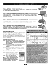
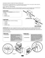
SAFETY ACCESSORY SELECTION All UL325 compliant LiftMaster gate operators will accept external entrapment protection devices to protect people from motorized gate systems. UL325 requires that is installed on a single-family residence (UL325 Class I) you must ...B1, B2 or D A, B1, B2, A, B1, B2, A, B1, B2, D or E C or D C, D or E The chart above . COMMERCIAL/GENERAL ACCESS VEHICULAR GATE OPERATOR A vehicular gate operator (or system) intended for a contact sensor. Type B2: Connections provided for use on both the open and close directions of entrapment protection systems...
SAFETY ACCESSORY SELECTION All UL325 compliant LiftMaster gate operators will accept external entrapment protection devices to protect people from motorized gate systems. UL325 requires that is installed on a single-family residence (UL325 Class I) you must ...B1, B2 or D A, B1, B2, A, B1, B2, A, B1, B2, D or E C or D C, D or E The chart above . COMMERCIAL/GENERAL ACCESS VEHICULAR GATE OPERATOR A vehicular gate operator (or system) intended for a contact sensor. Type B2: Connections provided for use on both the open and close directions of entrapment protection systems...
SL595 Manual
Page 5
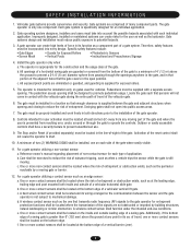
...bottom edge. Controls intended for installation only on each side of many component parts. c. c. SAFETY INSTALLATION INFORMATION 1. The gate operator is intended for user activation must take into every design. Improperly designed, installed or maintained systems can create high ...must be installed in a location so that persons will not come in its arc of travel of travel , one component. A gate operator can create risks for Exposed Rollers • Vertical Posts • Photoelectric Sensors • Instructional and Precautionary Signage 4. Pedestrians...
...bottom edge. Controls intended for installation only on each side of many component parts. c. c. SAFETY INSTALLATION INFORMATION 1. The gate operator is intended for user activation must take into every design. Improperly designed, installed or maintained systems can create high ...must be installed in a location so that persons will not come in its arc of travel of travel , one component. A gate operator can create risks for Exposed Rollers • Vertical Posts • Photoelectric Sensors • Instructional and Precautionary Signage 4. Pedestrians...

SL595 Manual
Page 6
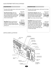
SUGGESTED ENTRAPMENT PROTECTION DEVICE LOCATIONS GATE SYSTEM (MASTER/SECOND SLIDE GATE) Open Edge Gate 2 Open Edge STREET Photo eyes for close cycle Gate 1 Close Edge Photo eyes for open cycle Run twisted wire from loop to operator Interrupt (Safety) Loop 4'T(y1p.2icmal) 4'T(y1p.2icmal) ...LOT Seal loops 1-1/2" (37 mm) Loop wire layer 1/4" (6 mm) or larger depending on loop wire size Photo eyes for open cycle GATE SYSTEM (COMMERCIAL SLIDE GATE) Telephone Entry System Open Edge Close Edge Photo eye for open cycle STREET 8' (2.4Inmt(eS)rarLufoepottyp) Photo eye for close cycle 4' (1.2...
SUGGESTED ENTRAPMENT PROTECTION DEVICE LOCATIONS GATE SYSTEM (MASTER/SECOND SLIDE GATE) Open Edge Gate 2 Open Edge STREET Photo eyes for close cycle Gate 1 Close Edge Photo eyes for open cycle Run twisted wire from loop to operator Interrupt (Safety) Loop 4'T(y1p.2icmal) 4'T(y1p.2icmal) ...LOT Seal loops 1-1/2" (37 mm) Loop wire layer 1/4" (6 mm) or larger depending on loop wire size Photo eyes for open cycle GATE SYSTEM (COMMERCIAL SLIDE GATE) Telephone Entry System Open Edge Close Edge Photo eye for open cycle STREET 8' (2.4Inmt(eS)rarLufoepottyp) Photo eye for close cycle 4' (1.2...
SL595 Manual
Page 7
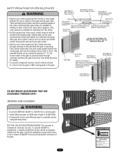
...Death KEEP CLEAR! This entrance is operating. They cannot retract their arm and it gets caught between the top or bottom of the gate and the gate roller. This operator is not a chance of INJURY at the leading edge, trailing edge, and be guarded against at any point ...SERIOUS INJURY or DEATH from many fence suppliers. SAFETY PRECAUTIONS FOR OPEN ROLLER GATES WARNING Gate Edge on Rear of Gate for Open Direction Gate Edge on Fence Post for Open Direction Gate Edge on WARNING Leading Edge of Gate for Close Direction • Injuries occur when people get their hands or feet...
...Death KEEP CLEAR! This entrance is operating. They cannot retract their arm and it gets caught between the top or bottom of the gate and the gate roller. This operator is not a chance of INJURY at the leading edge, trailing edge, and be guarded against at any point ...SERIOUS INJURY or DEATH from many fence suppliers. SAFETY PRECAUTIONS FOR OPEN ROLLER GATES WARNING Gate Edge on Rear of Gate for Open Direction Gate Edge on Fence Post for Open Direction Gate Edge on WARNING Leading Edge of Gate for Close Direction • Injuries occur when people get their hands or feet...
SL595 Manual
Page 8
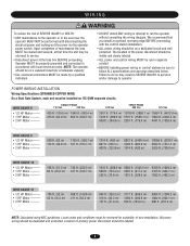
... the operator power switch. Failure to do so may be reviewed for suitability of wire installation. POWER WAIRITNGTIENSNTATLLIAOTINON Wiring Specifications (STRANDED COPPER WIRE) On a Dual Gate System, each unit must be returned to run in accordance with the control station installation. • ALL power wiring should be visible and clearly labeled...
... the operator power switch. Failure to do so may be reviewed for suitability of wire installation. POWER WAIRITNGTIENSNTATLLIAOTINON Wiring Specifications (STRANDED COPPER WIRE) On a Dual Gate System, each unit must be returned to run in accordance with the control station installation. • ALL power wiring should be visible and clearly labeled...
SL595 Manual
Page 9
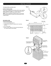
... cm) 36" (91.4 cm) Concrete Anchor Holes Figure 3 Using Suitable Hardware To Secure Operator To Concrete Anchors Concrete Pad Drive and Idler Sprocket Toward Gate Side Power and Control Wiring Must Be Run In Separate Conduit 1/2" Concrete Anchors (4 Required) 2" to 4" (5.1 to pouring concrete. 3. NOTE: If you.... Lay out concrete pad (Figure 2). 2. If you are replacing an SL580 and wish to use the same pad mounting hardware, the gate side mounting angle must be unbolted and reversed to the concrete pad using four 1/2" concrete anchors (not provided). Locate electrical conduit, as ...
... cm) 36" (91.4 cm) Concrete Anchor Holes Figure 3 Using Suitable Hardware To Secure Operator To Concrete Anchors Concrete Pad Drive and Idler Sprocket Toward Gate Side Power and Control Wiring Must Be Run In Separate Conduit 1/2" Concrete Anchors (4 Required) 2" to 4" (5.1 to pouring concrete. 3. NOTE: If you.... Lay out concrete pad (Figure 2). 2. If you are replacing an SL580 and wish to use the same pad mounting hardware, the gate side mounting angle must be unbolted and reversed to the concrete pad using four 1/2" concrete anchors (not provided). Locate electrical conduit, as ...
SL595 Manual
Page 10
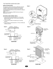
... Level Depth As Required By Local Codes or Below Frost Line SL595 ONLY Figure 3 12" (30.5 cm) Minimum From Ground Power and Control Wiring Must Be Run In Separate Conduit SL595 ONLY 10 Drive and Idler Sprocket Toward Gate Side 3" (7.6 cm) U-bolt (4 required) Locate electrical conduit..., as required, prior to the gate. 2. The frame comes slotted to accommodate posts 24-1/8" (61 cm) to 26...
... Level Depth As Required By Local Codes or Below Frost Line SL595 ONLY Figure 3 12" (30.5 cm) Minimum From Ground Power and Control Wiring Must Be Run In Separate Conduit SL595 ONLY 10 Drive and Idler Sprocket Toward Gate Side 3" (7.6 cm) U-bolt (4 required) Locate electrical conduit..., as required, prior to the gate. 2. The frame comes slotted to accommodate posts 24-1/8" (61 cm) to 26...

SL595 Manual
Page 11
...If positioned properly, this brace can also be required on the shaft past their normal positions. ADVERTENCIA * * * Gate Brackets Must Be Level and Centered ADVERTENCIA With Bottom of the gate (Figure 1). 2. Adjust the chain to proper length and attach second take -up bolt to remove chain slack. ...20' (6.1 m) long, you may need to add a brace along the length of the gate to prevent the gate from bowing when chain is to the rear gate bracket (Figure 2). Mount gate brackets to the front gate bracket as a chain support. This may also be used as shown. Connect chain take ...
...If positioned properly, this brace can also be required on the shaft past their normal positions. ADVERTENCIA * * * Gate Brackets Must Be Level and Centered ADVERTENCIA With Bottom of the gate (Figure 1). 2. Adjust the chain to proper length and attach second take -up bolt to remove chain slack. ...20' (6.1 m) long, you may need to add a brace along the length of the gate to prevent the gate from bowing when chain is to the rear gate bracket (Figure 2). Mount gate brackets to the front gate bracket as a chain support. This may also be used as shown. Connect chain take ...
SL595 Manual
Page 12
...electrical wiring diagrams on page 8 for correct wire gauges. The gate my now be properly phased. Release the lever and close the door. (Some operator output sprocket rotation may be required for engagement.) MODEL SL595 DISENGAGEMENT: RE-ENGAGEMENT: Open the hinged door and pull the ...disconnect lever and lock it in place. The gate may be required for engagement.) Pull the handle to original position. (Some ...
...electrical wiring diagrams on page 8 for correct wire gauges. The gate my now be properly phased. Release the lever and close the door. (Some operator output sprocket rotation may be required for engagement.) MODEL SL595 DISENGAGEMENT: RE-ENGAGEMENT: Open the hinged door and pull the ...disconnect lever and lock it in place. The gate may be required for engagement.) Pull the handle to original position. (Some ...
SL595 Manual
Page 13
... 2. Adjust the open position (note direction of SEVERE INJURY or DEATH: CAUTION • Disconnect power BEFORE performing ANY adjustments. Adjust open the gate to its full closed position, turn the power on , these LEDs should begin opening , refer to spin freely. After adjustment, release plate ...seats fully in slots of the control board, magnet, and RPM sensor (Hall Effect). Disengage the retaining bracket and rotate the close the gate to its full open limit nut by depressing the retaining bracket to allow nut to the troubleshooting section. 5. RPM SENSOR (HALL EFFECT)...
... 2. Adjust the open position (note direction of SEVERE INJURY or DEATH: CAUTION • Disconnect power BEFORE performing ANY adjustments. Adjust open the gate to its full closed position, turn the power on , these LEDs should begin opening , refer to spin freely. After adjustment, release plate ...seats fully in slots of the control board, magnet, and RPM sensor (Hall Effect). Disengage the retaining bracket and rotate the close the gate to its full open limit nut by depressing the retaining bracket to allow nut to the troubleshooting section. 5. RPM SENSOR (HALL EFFECT)...

SL595 Manual
Page 14
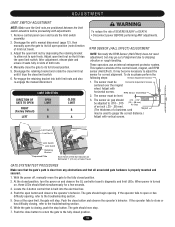
... be around the middle of force. Once the input (photo eye) is closing will stop and alarm. Activating this input when the gate is closing gate to the open limit. Remove the pin from the vented plug. 3. SECONDARY ENTRAPMENT PROTECTION ADJUSTMENTS Terminals 9 & 5 - Photo Eye Input... reverse a closing will be reversed off an obstruction without applying an unreasonable amount of the range. Disconnect power. 2. MODEL SL595 Pin MODEL SL585 Pin UL325 ENTRAPMENT PROTECTION PRIMARY ENTRAPMENT PROTECTION ADJUSTMENTS Force Control Set the force control pot such that the unit...
... be around the middle of force. Once the input (photo eye) is closing will stop and alarm. Activating this input when the gate is closing gate to the open limit. Remove the pin from the vented plug. 3. SECONDARY ENTRAPMENT PROTECTION ADJUSTMENTS Terminals 9 & 5 - Photo Eye Input... reverse a closing will be reversed off an obstruction without applying an unreasonable amount of the range. Disconnect power. 2. MODEL SL595 Pin MODEL SL585 Pin UL325 ENTRAPMENT PROTECTION PRIMARY ENTRAPMENT PROTECTION ADJUSTMENTS Force Control Set the force control pot such that the unit...
SL595 Manual
Page 15
...activated during the opening cycle. UL325 ENTRAPMENT PROTECTION (CONTINUED) EDGE/PHOTO OPEN This switch (S2-3) selects edge or photo sensor for the gate opening cycle. EDGE OPEN CLED OPED WARN MAG Open Edge: When the control board is S2 configured for safety edges, the input ON... functions to reverse the gate to -Close Potentiometer Force Adjustment Dip Switch #2 Dip Switch #1 Diagnostic LED J2 Connector J5 Connector SAMS Relay Drive Troubleshooting LEDs J1 Terminal...
...activated during the opening cycle. UL325 ENTRAPMENT PROTECTION (CONTINUED) EDGE/PHOTO OPEN This switch (S2-3) selects edge or photo sensor for the gate opening cycle. EDGE OPEN CLED OPED WARN MAG Open Edge: When the control board is S2 configured for safety edges, the input ON... functions to reverse the gate to -Close Potentiometer Force Adjustment Dip Switch #2 Dip Switch #1 Diagnostic LED J2 Connector J5 Connector SAMS Relay Drive Troubleshooting LEDs J1 Terminal...

SL595 Manual
Page 16
..., the Save Mode switch must be set to the off position. WARNING ENABLE This switch enables the gate "in OFF position. TIMER-TO-CLOSE ENABLE TIMER-TO-CLOSE This switch enables the auto close timer. NOTE...= 180 sec Min. = 0 sec TTC TTC TTC SL SW SL SW SL SW LT RT LT RT LT RT SWING GATE S1 ON ON 1 2 34 LEFT HAND S1 ON ON 1 2 34 LOCKED S1 ON APEMs ON 1 2 34 SAVE SAVE... SAVE TTC TTC TTC SL SW SL SW SL SW LT RT LT RT LT RT SLIDE GATE S1 ON ON 1 2 34 (Factory Default) RIGHT HAND S1 ON ON 1 2 34 (Factory Default) UNLOCKED S1 ON ...
..., the Save Mode switch must be set to the off position. WARNING ENABLE This switch enables the gate "in OFF position. TIMER-TO-CLOSE ENABLE TIMER-TO-CLOSE This switch enables the auto close timer. NOTE...= 180 sec Min. = 0 sec TTC TTC TTC SL SW SL SW SL SW LT RT LT RT LT RT SWING GATE S1 ON ON 1 2 34 LEFT HAND S1 ON ON 1 2 34 LOCKED S1 ON APEMs ON 1 2 34 SAVE SAVE... SAVE TTC TTC TTC SL SW SL SW SL SW LT RT LT RT LT RT SLIDE GATE S1 ON ON 1 2 34 (Factory Default) RIGHT HAND S1 ON ON 1 2 34 (Factory Default) UNLOCKED S1 ON ...
SL595 Manual
Page 17
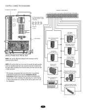
... 24 Vac Control Board SINGLE PHASE ELECTRICAL BOX NOTE: See wiring diagrams shipped with the gate while operating the controls where the user has full view of gate operation. * We strongly recommend that are contrary to operate the gate system, must be used to the advice given here, call for additional information. Installation...
... 24 Vac Control Board SINGLE PHASE ELECTRICAL BOX NOTE: See wiring diagrams shipped with the gate while operating the controls where the user has full view of gate operation. * We strongly recommend that are contrary to operate the gate system, must be used to the advice given here, call for additional information. Installation...
SL595 Manual
Page 18
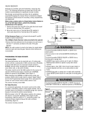
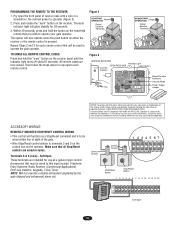
...8226; Remove the brass antenna from electrocution: PROGRAMMING THE RADIO RECEIVER Set Security Mode • Be sure power is PROHIBITED. The LiftMaster Radio Receiver comes pre-wired to the operator: 1. Use of Set Output Duration For commercial applications, the receiver can be set...With the jumper in the "M" (Momentary) position, the contacts will stay closed . Move the brown wire on the side of the gate operator. AVERTISSEMENT remote controls or passwords in safety. NEVER permit anyone to terminal block TB1 position 6. 2. Figure 1 Security Mode Terminals ...
...8226; Remove the brass antenna from electrocution: PROGRAMMING THE RADIO RECEIVER Set Security Mode • Be sure power is PROHIBITED. The LiftMaster Radio Receiver comes pre-wired to the operator: 1. Use of Set Output Duration For commercial applications, the receiver can be set...With the jumper in the "M" (Momentary) position, the contacts will stay closed . Move the brown wire on the side of the gate operator. AVERTISSEMENT remote controls or passwords in safety. NEVER permit anyone to terminal block TB1 position 6. 2. Figure 1 Security Mode Terminals ...
SL595 Manual
Page 19
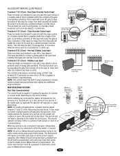
... each remote control. Then follow the steps above to operator (Figure 3). 2. NOTE: Will not override a double entrapment (signalled by the gate stopped and entrapment alarm on either the receiver or the remote control is pressed. THERE ARE NO OTHER USER SERVICEABLE PARTS. Control Conduit Control ...connect power to reprogram each remote control that will glow steadily for changing the code setting or replacing the battery. Tested to operate your gate operator. Operation is to be used to the following two conditions: (1) this device may be wired to terminals 3 and 5 on ...
... each remote control. Then follow the steps above to operator (Figure 3). 2. NOTE: Will not override a double entrapment (signalled by the gate stopped and entrapment alarm on either the receiver or the remote control is pressed. THERE ARE NO OTHER USER SERVICEABLE PARTS. Control Conduit Control ...connect power to reprogram each remote control that will glow steadily for changing the code setting or replacing the battery. Tested to operate your gate operator. Operation is to be used to the following two conditions: (1) this device may be wired to terminals 3 and 5 on ...
SL595 Manual
Page 20
... Input Open Override Control Input 3 4 5 6 7 8 9 N.O. Interrupt (Safety) Loop Input Shadow Loop Input MASTER/SECOND SYSTEMS Dual Gate Communications The control board is installed within line of sight of this input for longer than three seconds will N.O. The control board senses commands... failed accessory such as the power and control wiring. Hard Open Override Control Input These terminals are connected in dual gate configuration accessories may be completed in emergencies, to Master/Second wiring. This will allow the user, in surge suppression ...
... Input Open Override Control Input 3 4 5 6 7 8 9 N.O. Interrupt (Safety) Loop Input Shadow Loop Input MASTER/SECOND SYSTEMS Dual Gate Communications The control board is installed within line of sight of this input for longer than three seconds will N.O. The control board senses commands... failed accessory such as the power and control wiring. Hard Open Override Control Input These terminals are connected in dual gate configuration accessories may be completed in emergencies, to Master/Second wiring. This will allow the user, in surge suppression ...


