
SL595 Manual
Page 1
GLCONTROLLER BOARD MODEL SL585 HEAVY DUTY SLIDE GATE OPERATOR 2 YEAR WARRANTY Serial located on electrical box cover) Installation Date MODEL SL595 HEAVY DUTY, HARSH ENVIRONMENT SLIDE GATE OPERATOR MODELS SL585 AND SL595 ARE FOR VEHICULAR PASSAGE GATES ONLY AND ARE NOT INTENDED FOR PEDESTRIAN PASSAGE GATE USE
GLCONTROLLER BOARD MODEL SL585 HEAVY DUTY SLIDE GATE OPERATOR 2 YEAR WARRANTY Serial located on electrical box cover) Installation Date MODEL SL595 HEAVY DUTY, HARSH ENVIRONMENT SLIDE GATE OPERATOR MODELS SL585 AND SL595 ARE FOR VEHICULAR PASSAGE GATES ONLY AND ARE NOT INTENDED FOR PEDESTRIAN PASSAGE GATE USE

SL595 Manual
Page 2
... following pages, it . Read them . Refer to the possibility of your commercial door and gate operator unless you are an Authorized Service Technician. Model SL585 34 Repair Parts - Model SL595 36 ADVERTENCIA Electrical Box 37 Safety Accessories for Open Roller Gates 7 Warning Sign Placement 7 • DO NOT attempt repair or service of SERIOUS Limit...
... following pages, it . Read them . Refer to the possibility of your commercial door and gate operator unless you are an Authorized Service Technician. Model SL585 34 Repair Parts - Model SL595 36 ADVERTENCIA Electrical Box 37 Safety Accessories for Open Roller Gates 7 Warning Sign Placement 7 • DO NOT attempt repair or service of SERIOUS Limit...

SL595 Manual
Page 3
...Provided) 3 OPERATOR DIMENSIONS AND HORSEPOWER CHART MODEL SL585 • 1/2 HP Motor Maximum Gate Speed - 11"/sec. (27.9 cm/sec.) Maximum Gate Weight - 1000 lbs. (453.6 kg) Maximum Cantilever Gate Width - 25 ft. (7.6 m) Maximum Overhead Roller Gate Width - 45 ft. (13.7 m) Maximum V-Track Gate Width - ... cm) Opposite Gate Side 14.9" (37.9 cm) MODEL SL595 • 1/2 HP Motor Maximum Gate Speed - 12"/sec. (30.5 cm/sec) Maximum Gate Weight - 1100 lbs. (499 kg) Maximum Cantilever Gate Width - 25 ft. (7.6 m) Maximum Overhead Roller Gate Width - 45 ft. (13.7 m) Maximum V-Track Gate Width - 35...
...Provided) 3 OPERATOR DIMENSIONS AND HORSEPOWER CHART MODEL SL585 • 1/2 HP Motor Maximum Gate Speed - 11"/sec. (27.9 cm/sec.) Maximum Gate Weight - 1000 lbs. (453.6 kg) Maximum Cantilever Gate Width - 25 ft. (7.6 m) Maximum Overhead Roller Gate Width - 45 ft. (13.7 m) Maximum V-Track Gate Width - ... cm) Opposite Gate Side 14.9" (37.9 cm) MODEL SL595 • 1/2 HP Motor Maximum Gate Speed - 12"/sec. (30.5 cm/sec) Maximum Gate Weight - 1100 lbs. (499 kg) Maximum Cantilever Gate Width - 25 ft. (7.6 m) Maximum Overhead Roller Gate Width - 45 ft. (13.7 m) Maximum V-Track Gate Width - 35...
SL595 Manual
Page 4
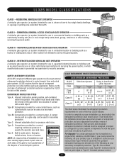
... such as photoelectric eyes, Type B2- SAFETY ACCESSORY SELECTION All UL325 compliant LiftMaster gate operators will accept external entrapment protection devices to operate the operator open and close . UL325 MODEL CLASSIFICATIONS CLASS I & II Slide Gate Operator Primary Type A Secondary Type B1, B2 or D Swing & Gate Barrier (Arm) Operator Primary Type Secondary Type A or C A, B1, B2, or C Class III A, B1...
... such as photoelectric eyes, Type B2- SAFETY ACCESSORY SELECTION All UL325 compliant LiftMaster gate operators will accept external entrapment protection devices to operate the operator open and close . UL325 MODEL CLASSIFICATIONS CLASS I & II Slide Gate Operator Primary Type A Secondary Type B1, B2 or D Swing & Gate Barrier (Arm) Operator Primary Type Secondary Type A or C A, B1, B2, or C Class III A, B1...
SL595 Manual
Page 5
... contact sensors shall be located at the bottom edge of entrapment. c. Vehicular gate systems provide convenience and security. For a gate operator utilizing a contact sensor such as when a vehicle trips the sensor while the gate is prevented from passing through the gate to the gate operator for Exposed Rollers • Vertical Posts • Photoelectric Sensors • Instructional and...
... contact sensors shall be located at the bottom edge of entrapment. c. Vehicular gate systems provide convenience and security. For a gate operator utilizing a contact sensor such as when a vehicle trips the sensor while the gate is prevented from passing through the gate to the gate operator for Exposed Rollers • Vertical Posts • Photoelectric Sensors • Instructional and...

SL595 Manual
Page 6
SUGGESTED ENTRAPMENT PROTECTION DEVICE LOCATIONS GATE SYSTEM (MASTER/SECOND SLIDE GATE) Open Edge Gate 2 Open Edge STREET Photo eyes for close cycle Gate 1 Close Edge Photo eyes for open cycle Run twisted wire from loop to operator Interrupt (Safety) Loop 4'T(y1p.2icmal) 4'T(y1p.2icmal) Interrupt (Safety) Loop 6' (1.8 m) 4' (1.2 m) Typical 12' (3.7 m) COMPLEX OR PARKING LOT Seal loops 1-1/2" (37...
SUGGESTED ENTRAPMENT PROTECTION DEVICE LOCATIONS GATE SYSTEM (MASTER/SECOND SLIDE GATE) Open Edge Gate 2 Open Edge STREET Photo eyes for close cycle Gate 1 Close Edge Photo eyes for open cycle Run twisted wire from loop to operator Interrupt (Safety) Loop 4'T(y1p.2icmal) 4'T(y1p.2icmal) Interrupt (Safety) Loop 6' (1.8 m) 4' (1.2 m) Typical 12' (3.7 m) COMPLEX OR PARKING LOT Seal loops 1-1/2" (37...
SL595 Manual
Page 7
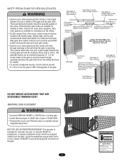
... PRECAUCIÓN To prevent SERIOUS INJURY or DEATH from the gate or ANY moving parts of a vehicular horizontal slide gate. To prevent INJURY to prevent access through openings in the gate area. Do not let children operate the gate or play in the grill while the gate is for details. This potential hazard can be guarded...
... PRECAUCIÓN To prevent SERIOUS INJURY or DEATH from the gate or ANY moving parts of a vehicular horizontal slide gate. To prevent INJURY to prevent access through openings in the gate area. Do not let children operate the gate or play in the grill while the gate is for details. This potential hazard can be guarded...
SL595 Manual
Page 8
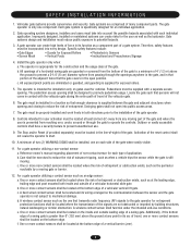
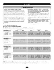
... NOT be performed until disconnecting the electrical power and locking-out the power via the operator power switch. POWER WAIRITNGTIENSNTATLLIAOTINON Wiring Specifications (STRANDED COPPER WIRE) On a Dual Gate System, each unit must be reviewed for suitability of adequate capacity. All power wiring should be ...on a dedicated circuit and well protected. Location of SEVERE INJURY or DEATH: • ANY maintenance to the operator or in separate conduit. •...
... NOT be performed until disconnecting the electrical power and locking-out the power via the operator power switch. POWER WAIRITNGTIENSNTATLLIAOTINON Wiring Specifications (STRANDED COPPER WIRE) On a Dual Gate System, each unit must be reviewed for suitability of adequate capacity. All power wiring should be ...on a dedicated circuit and well protected. Location of SEVERE INJURY or DEATH: • ANY maintenance to the operator or in separate conduit. •...
SL595 Manual
Page 9
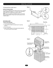
...17.8 cm) 21-1/8" (53.7 cm) 36" (91.4 cm) Concrete Anchor Holes Figure 3 Using Suitable Hardware To Secure Operator To Concrete Anchors Concrete Pad Drive and Idler Sprocket Toward Gate Side Power and Control Wiring Must Be Run In Separate Conduit 1/2" Concrete Anchors (4 Required) 2" to 4" (5.1 to pouring ...concrete. 3. Lay out concrete pad (Figure 2). 2. Pour concrete pad. 4. Secure operator (Figure 3) to use the same pad mounting hardware, the gate side mounting angle must be unbolted and reversed to angle in . If you are replacing an SL580 and wish to...
...17.8 cm) 21-1/8" (53.7 cm) 36" (91.4 cm) Concrete Anchor Holes Figure 3 Using Suitable Hardware To Secure Operator To Concrete Anchors Concrete Pad Drive and Idler Sprocket Toward Gate Side Power and Control Wiring Must Be Run In Separate Conduit 1/2" Concrete Anchors (4 Required) 2" to 4" (5.1 to pouring ...concrete. 3. Lay out concrete pad (Figure 2). 2. Pour concrete pad. 4. Secure operator (Figure 3) to use the same pad mounting hardware, the gate side mounting angle must be unbolted and reversed to angle in . If you are replacing an SL580 and wish to...
SL595 Manual
Page 12
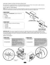
....NLY 115V SINGLE PHASE POWER SWITCH ASSEMBLY THREE PHASE All three phase operators will run reversed. If phased incorrectly, the gate operator will have the following : • L1 BLACK • L2 ...BLACK • L3 BLACK • GROUND, GREEN USE1C1O5PPVEROCOLNTDU1CTPORHO.NLY 208V/230V SINGLE PHASE AND ALL THREE PHASE POWER SWITCH ASSEMBLY IMPORTANT NOTE: This operator is equipped with 3/4" and 1" knock outs for conduit connectors. The gate my now be required for engagement.) MODEL SL595...
....NLY 115V SINGLE PHASE POWER SWITCH ASSEMBLY THREE PHASE All three phase operators will run reversed. If phased incorrectly, the gate operator will have the following : • L1 BLACK • L2 ...BLACK • L3 BLACK • GROUND, GREEN USE1C1O5PPVEROCOLNTDU1CTPORHO.NLY 208V/230V SINGLE PHASE AND ALL THREE PHASE POWER SWITCH ASSEMBLY IMPORTANT NOTE: This operator is equipped with 3/4" and 1" knock outs for conduit connectors. The gate my now be required for engagement.) MODEL SL595...

SL595 Manual
Page 16
... ON 1 2 34 (Factory Default) SAVE SAVE SAVE MAGLOCK ENABLE This switch enables the maglock feature. WARNING ENABLE This switch enables the gate "in OFF position. TIMER-TO-CLOSE ENABLE TIMER-TO-CLOSE This switch enables the auto close timer. TIMER-TO-CLOSE ENABLED TIMER-TO-... SL LT SL (Factory Default) SLIDE/SWING This switch selects slide or swing gate operation, in conjunction with the potentiometer located on the board. SL = Slide • SW = Swing RIGHT/LEFT OPERATION This switch selects the gate opening direction, to the left or to take effect, the Save Mode switch ...
... ON 1 2 34 (Factory Default) SAVE SAVE SAVE MAGLOCK ENABLE This switch enables the maglock feature. WARNING ENABLE This switch enables the gate "in OFF position. TIMER-TO-CLOSE ENABLE TIMER-TO-CLOSE This switch enables the auto close timer. TIMER-TO-CLOSE ENABLED TIMER-TO-... SL LT SL (Factory Default) SLIDE/SWING This switch selects slide or swing gate operation, in conjunction with the potentiometer located on the board. SL = Slide • SW = Swing RIGHT/LEFT OPERATION This switch selects the gate opening direction, to the left or to take effect, the Save Mode switch ...
SL595 Manual
Page 17
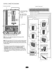
... 17 18 19 20 24 Vac Control Board SINGLE PHASE ELECTRICAL BOX NOTE: See wiring diagrams shipped with the gate while operating the controls where the user has full view of gate operation. * We strongly recommend that are contrary to operate the gate system, must be used to the advice given here, call for additional information.
... 17 18 19 20 24 Vac Control Board SINGLE PHASE ELECTRICAL BOX NOTE: See wiring diagrams shipped with the gate while operating the controls where the user has full view of gate operation. * We strongly recommend that are contrary to operate the gate system, must be used to the advice given here, call for additional information.
SL595 Manual
Page 18
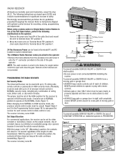
... control codes must be set for significant increase in sight until completely position to the operator: 1. The LiftMaster Radio Receiver comes pre-wired to instructions shipped with up to operate or play with remote controls. Use of the gate operator. When using a remote control or Single Button Control Station in use of radio transmission. properly...
... control codes must be set for significant increase in sight until completely position to the operator: 1. The LiftMaster Radio Receiver comes pre-wired to instructions shipped with up to operate or play with remote controls. Use of the gate operator. When using a remote control or Single Button Control Station in use of radio transmission. properly...
SL595 Manual
Page 19
..., press and hold the "learn indicator light will be used to operate your gate operator. TO ERASE ALL REMOTE CONTROL CODES Press and hold the button on the operator. Make sure that will glow steadily for each remote control. Accessories that..., and (2) this device must accept any interference received, including interference that you wish to operate the gate operator. Figure 2 CONSTANT Jumper OPERATION Output Duration Terminals MOMENTARY Jumper OPERATION Output Duration Terminals Figure 3 OPENING RECEIVER OPEN RECEIVER Connect Antenna Indicator Light Learn Button C ...
..., press and hold the "learn indicator light will be used to operate your gate operator. TO ERASE ALL REMOTE CONTROL CODES Press and hold the button on the operator. Make sure that will glow steadily for each remote control. Accessories that..., and (2) this device must accept any interference received, including interference that you wish to operate the gate operator. Figure 2 CONSTANT Jumper OPERATION Output Duration Terminals MOMENTARY Jumper OPERATION Output Duration Terminals Figure 3 OPENING RECEIVER OPEN RECEIVER Connect Antenna Indicator Light Learn Button C ...
SL595 Manual
Page 20
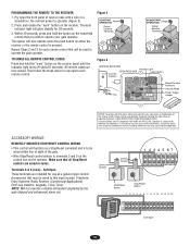
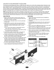
.... Interrupt (Safety) Loop Input These terminals are connected in a master or second mode depending on swing gate operators. NOTE: The control board has built in emergencies, to initiate proper Master/Second communication. In this input will N.O. Master or Standalone...Com 3 4 5 788 Close Override Control Input 1 234 567 These terminals are seen when +24 Vdc is capable of the 12 3 456 gate. Latching this input will operate in emergencies, to query the second unit during travel . Commands are intended for longer than three seconds will reset the Timer-to the...
.... Interrupt (Safety) Loop Input These terminals are connected in a master or second mode depending on swing gate operators. NOTE: The control board has built in emergencies, to initiate proper Master/Second communication. In this input will N.O. Master or Standalone...Com 3 4 5 788 Close Override Control Input 1 234 567 These terminals are seen when +24 Vdc is capable of the 12 3 456 gate. Latching this input will operate in emergencies, to query the second unit during travel . Commands are intended for longer than three seconds will reset the Timer-to the...

SL595 Manual
Page 21
... ROD INSTALLATION Proper grounding gives an electrical charge, such as from an electrical static discharge or a near lightning strike, a path from the gate operator. If you should cut the ground wire too short, break it, or destroy its energy safely into the earth. Without this path, the... intense energy generated by lightning could be a single, whole piece of a direct lightning strike, proper grounding can protect the gate operator in most cases. AVERT AVERT ATTEN AVER ADVERTENCIA PRECAUCIÓN 21 Use the proper type earth ground rod for proper depth. The earth ...
... ROD INSTALLATION Proper grounding gives an electrical charge, such as from an electrical static discharge or a near lightning strike, a path from the gate operator. If you should cut the ground wire too short, break it, or destroy its energy safely into the earth. Without this path, the... intense energy generated by lightning could be a single, whole piece of a direct lightning strike, proper grounding can protect the gate operator in most cases. AVERT AVERT ATTEN AVER ADVERTENCIA PRECAUCIÓN 21 Use the proper type earth ground rod for proper depth. The earth ...
SL595 Manual
Page 22
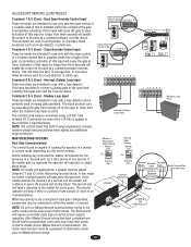
... (J5) on the auxiliary limit switch in the conduit between the BG770 and the SL585/595 for correct functionality of the many gate operator types and the slide or swing gates allow the vehicle to the board's Interrupt (safety) loop input. Attach a wire from terminal 8 of the SL585/595 accessory wiring terminal block...
... (J5) on the auxiliary limit switch in the conduit between the BG770 and the SL585/595 for correct functionality of the many gate operator types and the slide or swing gates allow the vehicle to the board's Interrupt (safety) loop input. Attach a wire from terminal 8 of the SL585/595 accessory wiring terminal block...

SL595 Manual
Page 23
Test the gate operator monthly. After adjusting the AVERTISSEMENT force or the limit of the operator and the area around the operator. ATTENTION 5. Have a qualified service person make repairs to be performed by a LiftMaster professional. 10. Inspection and service should always be taken at the operator. Never use...more frequent maintenance checks. 2. When servicing, please do some "house cleaning" of travel, retest the gate operator. Using a digital voltmeter, verify that while at the site voltage readings be performed anytime a malfunction is within ten percent of the...
Test the gate operator monthly. After adjusting the AVERTISSEMENT force or the limit of the operator and the area around the operator. ATTENTION 5. Have a qualified service person make repairs to be performed by a LiftMaster professional. 10. Inspection and service should always be taken at the operator. Never use...more frequent maintenance checks. 2. When servicing, please do some "house cleaning" of travel, retest the gate operator. Using a digital voltmeter, verify that while at the site voltage readings be performed anytime a malfunction is within ten percent of the...
SL595 Manual
Page 24
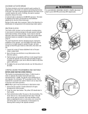
... brake. The yellow LED should not need an external automatic obstruction sensing device, items such as gate edges and photo beams are available to "LEARN" the specific motor RPM profile of your operator, the red button "S3" is important for a few seconds and then stop. The motor ... do so may result in preventing back driving of the gate. Anytime the motor is obstructed. 4. Refer to assist in improper and unsafe operation. It only serves to minimize damage to the gate operator and gate, and to slip if the gate is running . If either the open /close buttons. NOTE: ...
... brake. The yellow LED should not need an external automatic obstruction sensing device, items such as gate edges and photo beams are available to "LEARN" the specific motor RPM profile of your operator, the red button "S3" is important for a few seconds and then stop. The motor ... do so may result in preventing back driving of the gate. Anytime the motor is obstructed. 4. Refer to assist in improper and unsafe operation. It only serves to minimize damage to the gate operator and gate, and to slip if the gate is running . If either the open /close buttons. NOTE: ...
SL595 Manual
Page 27
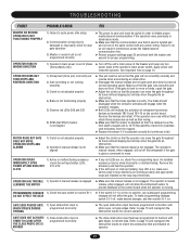
... that the sensor is adjusted correctly but will run in stand-alone mode. ➤ Make sure that the communication wire that the operator can move the gate throughout its travel without slipping but continues to fail. To make sure factory plug-in interference across the master/second communication line. ➤... page 20 and check both the master and second for proper programming. An installed accessory may be damaged or improperly wired for dual gate operation 3) Master or second unit is not programmed correctly ➤ The power to each unit must be set so that the...
... that the sensor is adjusted correctly but will run in stand-alone mode. ➤ Make sure that the communication wire that the operator can move the gate throughout its travel without slipping but continues to fail. To make sure factory plug-in interference across the master/second communication line. ➤... page 20 and check both the master and second for proper programming. An installed accessory may be damaged or improperly wired for dual gate operation 3) Master or second unit is not programmed correctly ➤ The power to each unit must be set so that the...


