
SL595 Manual
Page 2
...SL585 only 9 Post Mounting (SL585 & SL595 10 CAUTION Install Gate Bracket and Drive Chain 11 Available Conduit Access for Open Roller Gates 7 Warning Sign Placement 7 • DO NOT attempt repair or service of your commercial door and gate operator unless you MUST read and fully understand...the cautionary statements that Program Settings 16 accompany it. Model SL595 35 Illustrated Parts - The hazard may come from something Gate System Test Procedures 13 mechanical or from electric shock. Model SL595 36 ADVERTENCIA Electrical Box 37 Safety Accessories for factory provided ...
...SL585 only 9 Post Mounting (SL585 & SL595 10 CAUTION Install Gate Bracket and Drive Chain 11 Available Conduit Access for Open Roller Gates 7 Warning Sign Placement 7 • DO NOT attempt repair or service of your commercial door and gate operator unless you MUST read and fully understand...the cautionary statements that Program Settings 16 accompany it. Model SL595 35 Illustrated Parts - The hazard may come from something Gate System Test Procedures 13 mechanical or from electric shock. Model SL595 36 ADVERTENCIA Electrical Box 37 Safety Accessories for factory provided ...

SL595 Manual
Page 3
....9" (32.8 cm) Opposite Gate Side 14.9" (37.9 cm) MODEL SL595 • 1/2 HP Motor Maximum Gate Speed - 12"/sec. (30.5 cm/sec) Maximum Gate Weight - 1100 lbs. (499 kg) Maximum Cantilever Gate Width - 25 ft. (7.6 m) Maximum Overhead Roller Gate Width - 45 ft. (13.7 m) Maximum V-Track Gate Width - 35 ft. (10...Gate Weight - 2500 lbs. (1134 kg) Maximum Cantilever Gate Width - 45 ft. (13.7 m) Maximum Overhead Roller Gate Width - 90 ft. (27.4 m) Maximum V-Track Gate Width - 60 ft. (18.3 m) 24" (61 cm) Gate Side 16.5" (41.9 cm) 13.5" (34.3 cm) 22.5" (57.2 cm) 30" (76.2 cm) Allow For Door Opening...
....9" (32.8 cm) Opposite Gate Side 14.9" (37.9 cm) MODEL SL595 • 1/2 HP Motor Maximum Gate Speed - 12"/sec. (30.5 cm/sec) Maximum Gate Weight - 1100 lbs. (499 kg) Maximum Cantilever Gate Width - 25 ft. (7.6 m) Maximum Overhead Roller Gate Width - 45 ft. (13.7 m) Maximum V-Track Gate Width - 35 ft. (10...Gate Weight - 2500 lbs. (1134 kg) Maximum Cantilever Gate Width - 45 ft. (13.7 m) Maximum Overhead Roller Gate Width - 90 ft. (27.4 m) Maximum V-Track Gate Width - 60 ft. (18.3 m) 24" (61 cm) Gate Side 16.5" (41.9 cm) 13.5" (34.3 cm) 22.5" (57.2 cm) 30" (76.2 cm) Allow For Door Opening...
SL595 Manual
Page 4
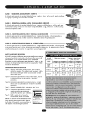
... family dwellings, or a garage or parking area associated therewith. In order to operate the operator open and close . Non-contact sensors such as gate edges or Type D- Constant pressure control. 4 SAFETY ACCESSORY SELECTION All UL325 compliant LiftMaster gate operators will accept external entrapment protection devices to protect against entrapments in a industrial location or building...
... family dwellings, or a garage or parking area associated therewith. In order to operate the operator open and close . Non-contact sensors such as gate edges or Type D- Constant pressure control. 4 SAFETY ACCESSORY SELECTION All UL325 compliant LiftMaster gate operators will accept external entrapment protection devices to protect against entrapments in a industrial location or building...
SL595 Manual
Page 5
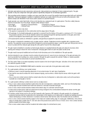
...bottom edge of a horizontal swing gate are not obstructed or impeded by a moving gate or barrier. 12. The gate must be supplied with the vehicular gate during the entire path of travel , one component. c. e. c. Swinging gates shall not open position. Outdoor or easily accessible... its wiring arranged so the communication between the gate and adjacent structures when opening shall be located where the risk of a gate system. The pedestrian access opening and closing to promote pedestrian usage. The gate must take into public access areas. 7. One...
...bottom edge of a horizontal swing gate are not obstructed or impeded by a moving gate or barrier. 12. The gate must be supplied with the vehicular gate during the entire path of travel , one component. c. e. c. Swinging gates shall not open position. Outdoor or easily accessible... its wiring arranged so the communication between the gate and adjacent structures when opening shall be located where the risk of a gate system. The pedestrian access opening and closing to promote pedestrian usage. The gate must take into public access areas. 7. One...

SL595 Manual
Page 6
SUGGESTED ENTRAPMENT PROTECTION DEVICE LOCATIONS GATE SYSTEM (MASTER/SECOND SLIDE GATE) Open Edge Gate 2 Open Edge STREET Photo eyes for close cycle Gate 1 Close Edge Photo eyes for open cycle Run twisted wire from loop to operator Interrupt (Safety) Loop 4'T(y1p.2icmal) 4'T(y1p.2icmal) Interrupt (...mm) Loop wire layer 1/4" (6 mm) or larger depending on loop wire size Photo eyes for open cycle GATE SYSTEM (COMMERCIAL SLIDE GATE) Telephone Entry System Open Edge Close Edge Photo eye for open cycle STREET 8' (2.4Inmt(eS)rarLufoepottyp) Photo eye for close cycle 4' (1.2 m) Typical 4' (...
SUGGESTED ENTRAPMENT PROTECTION DEVICE LOCATIONS GATE SYSTEM (MASTER/SECOND SLIDE GATE) Open Edge Gate 2 Open Edge STREET Photo eyes for close cycle Gate 1 Close Edge Photo eyes for open cycle Run twisted wire from loop to operator Interrupt (Safety) Loop 4'T(y1p.2icmal) 4'T(y1p.2icmal) Interrupt (...mm) Loop wire layer 1/4" (6 mm) or larger depending on loop wire size Photo eyes for open cycle GATE SYSTEM (COMMERCIAL SLIDE GATE) Telephone Entry System Open Edge Close Edge Photo eye for open cycle STREET 8' (2.4Inmt(eS)rarLufoepottyp) Photo eye for close cycle 4' (1.2 m) Typical 4' (...
SL595 Manual
Page 7
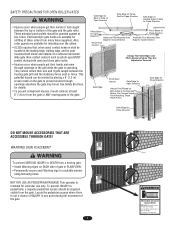
... fence. Locate the pedestrian access where there is operating. Gate may travel. Enclosed style gate tracks are available for details. SAFETY PRECAUTIONS FOR OPEN ROLLER GATES WARNING Gate Edge on Rear of Gate for Open Direction Gate Edge on Fence Post for Open Direction Gate Edge on WARNING Leading Edge of Gate for Close Direction • Injuries occur when people get...
... fence. Locate the pedestrian access where there is operating. Gate may travel. Enclosed style gate tracks are available for details. SAFETY PRECAUTIONS FOR OPEN ROLLER GATES WARNING Gate Edge on Rear of Gate for Open Direction Gate Edge on Fence Post for Open Direction Gate Edge on WARNING Leading Edge of Gate for Close Direction • Injuries occur when people get...

SL595 Manual
Page 11
... not overtighten chain. If positioned properly, this brace can also be required on some cantilever gates over 20' (6.1 m) long, you may also be used as shown. Remove the operator cover or open access door. 2" (5.1 cm) U-bolts With Lock Washers AVERTISSEMENT 3. Connect chain take ...-up bolt to the end of gates that the drive and idler sprockets are constructed out of aluminum. Anti-Rotation ...
... not overtighten chain. If positioned properly, this brace can also be required on some cantilever gates over 20' (6.1 m) long, you may also be used as shown. Remove the operator cover or open access door. 2" (5.1 cm) U-bolts With Lock Washers AVERTISSEMENT 3. Connect chain take ...-up bolt to the end of gates that the drive and idler sprockets are constructed out of aluminum. Anti-Rotation ...
SL595 Manual
Page 12
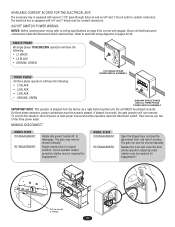
... specifications on pages 29-32. On three phase operators, power connections must be moved manually. The gate may be required for engagement.) MODEL SL595 DISENGAGEMENT: RE-ENGAGEMENT: Open the hinged door and pull the disconnect lever and lock it in place. Rotate handle back to ... the lever and close the door. (Some operator output sprocket rotation may be required for correct wire gauges. If phased incorrectly, the gate operator will have the following : • L1 WHITE • L2 BLACK • GROUND, GREEN USE1C1O5PPVEROCOLNTDU1CTPORHO.NLY 115V SINGLE PHASE POWER...
... specifications on pages 29-32. On three phase operators, power connections must be moved manually. The gate may be required for engagement.) MODEL SL595 DISENGAGEMENT: RE-ENGAGEMENT: Open the hinged door and pull the disconnect lever and lock it in place. Rotate handle back to ... the lever and close the door. (Some operator output sprocket rotation may be required for correct wire gauges. If phased incorrectly, the gate operator will have the following : • L1 WHITE • L2 BLACK • GROUND, GREEN USE1C1O5PPVEROCOLNTDU1CTPORHO.NLY 115V SINGLE PHASE POWER...
SL595 Manual
Page 13
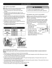
...an inch (.25 - .38 mm). (The thickness of the control board, magnet, and RPM sensor (Hall Effect). Once at the open or has difficulty opening . While the gate is built into both nuts. 4. Remove control panel cover and locate the limit switch assembly. 2. To do so please perform the ... ADJUSTMENT NOTE: Make sure the limit nuts are positioned between the limit switch actuators before proceeding with horizontal screws. Adjust open limit nut so that all associated gate hardware is turned on and observe the GL controller board's diagnostic and limit LEDs. It may be used to close...
...an inch (.25 - .38 mm). (The thickness of the control board, magnet, and RPM sensor (Hall Effect). Once at the open or has difficulty opening . While the gate is built into both nuts. 4. Remove control panel cover and locate the limit switch assembly. 2. To do so please perform the ... ADJUSTMENT NOTE: Make sure the limit nuts are positioned between the limit switch actuators before proceeding with horizontal screws. Adjust open limit nut so that all associated gate hardware is turned on and observe the GL controller board's diagnostic and limit LEDs. It may be used to close...

SL595 Manual
Page 14
...no effect. Once the input (photo eye) is detected (gate edge or RPM sensor), gate will stop and alarm. This input will reverse a closing gate to open limit. This input will complete a full cycle of gate travel but can be reversed off an obstruction without applying .... MODEL SL595 Pin MODEL SL585 Pin UL325 ENTRAPMENT PROTECTION PRIMARY ENTRAPMENT PROTECTION ADJUSTMENTS Force Control Set the force control pot such that the unit will not affect the Timer-to the close limit. This input will pause an opening gate to -Close. This input will reverse an opening gate. Terminals...
...no effect. Once the input (photo eye) is detected (gate edge or RPM sensor), gate will stop and alarm. This input will reverse a closing gate to open limit. This input will complete a full cycle of gate travel but can be reversed off an obstruction without applying .... MODEL SL595 Pin MODEL SL585 Pin UL325 ENTRAPMENT PROTECTION PRIMARY ENTRAPMENT PROTECTION ADJUSTMENTS Force Control Set the force control pot such that the unit will not affect the Timer-to the close limit. This input will pause an opening gate to -Close. This input will reverse an opening gate. Terminals...
SL595 Manual
Page 15
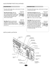
... may be disabled. The Timer-to pause the gate ON during the close cycle. UL325 ENTRAPMENT PROTECTION (CONTINUED) EDGE/PHOTO OPEN This switch (S2-3) selects edge or photo sensor for the gate opening cycle. EDGE OPEN CLED OPED WARN MAG Open Edge: When the control board is configured for ...photo eyes, the input functions to reverse the gate to the close cycle. ON The...
... may be disabled. The Timer-to pause the gate ON during the close cycle. UL325 ENTRAPMENT PROTECTION (CONTINUED) EDGE/PHOTO OPEN This switch (S2-3) selects edge or photo sensor for the gate opening cycle. EDGE OPEN CLED OPED WARN MAG Open Edge: When the control board is configured for ...photo eyes, the input functions to reverse the gate to the close cycle. ON The...

SL595 Manual
Page 16
...switch selects slide or swing gate operation, in order to the right. NOTE: For any programming changes to take effect, the Save Mode switch must be set to the off position. SL = Slide • SW = Swing RIGHT/LEFT OPERATION This switch selects the gate opening direction, to the left or... to optimize gate behavior for specific application. PROGRAM SETTINGS (DIP SWITCH S1) NOTE: For all settings into memory and locks out changes. Right/...
...switch selects slide or swing gate operation, in order to the right. NOTE: For any programming changes to take effect, the Save Mode switch must be set to the off position. SL = Slide • SW = Swing RIGHT/LEFT OPERATION This switch selects the gate opening direction, to the left or... to optimize gate behavior for specific application. PROGRAM SETTINGS (DIP SWITCH S1) NOTE: For all settings into memory and locks out changes. Right/...
SL595 Manual
Page 17
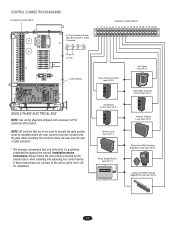
... ELECTRICAL BOX NOTE: See wiring diagrams shipped with the gate while operating the controls where the user has full view of gate operation. * We strongly recommend that are contrary to operate the gate system, must be used to the advice given here,...Override Control Input (N.O.) OPEN CLOSE STOP Stop/Reset Control Input (N.C.) OPEN CLOSE STOP Shadow Loop Input (N.O.) Radio (Single Button) Input (N.O.) FREQ FREQ Soft Open Input (N.O.) 123 56 789 0# Hard Open Override Control Input (N.O.) OPEN CLOSE STOP Interrupt (Safety) Loop Input (N.O.) Obstruction While Opening Edge/Photo Eye Input...
... ELECTRICAL BOX NOTE: See wiring diagrams shipped with the gate while operating the controls where the user has full view of gate operation. * We strongly recommend that are contrary to operate the gate system, must be used to the advice given here,...Override Control Input (N.O.) OPEN CLOSE STOP Stop/Reset Control Input (N.C.) OPEN CLOSE STOP Shadow Loop Input (N.O.) Radio (Single Button) Input (N.O.) FREQ FREQ Soft Open Input (N.O.) 123 56 789 0# Hard Open Override Control Input (N.O.) OPEN CLOSE STOP Interrupt (Safety) Loop Input (N.O.) Obstruction While Opening Edge/Photo Eye Input...
SL595 Manual
Page 18
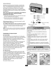
...Figure 2). constant or momentary closure on radio terminal block. The receiver is code, billion code, or dip switch remotes. The LiftMaster Radio Receiver comes pre-wired to the operator WARNING • Remove the brass antenna from the accessary box and screw it overrides... (Figure 1). Remote control devices are no obstructions to travel. NEVER permit anyone to open and momentary, except the stop (N.C.). Use of moving gate or ATTENTION When changing from a moving gate or garage door: The Universal Receiver can be erased. Remove the green wire from ...
...Figure 2). constant or momentary closure on radio terminal block. The receiver is code, billion code, or dip switch remotes. The LiftMaster Radio Receiver comes pre-wired to the operator WARNING • Remove the brass antenna from the accessary box and screw it overrides... (Figure 1). Remote control devices are no obstructions to travel. NEVER permit anyone to open and momentary, except the stop (N.C.). Use of moving gate or ATTENTION When changing from a moving gate or garage door: The Universal Receiver can be erased. Remove the green wire from ...
SL595 Manual
Page 19
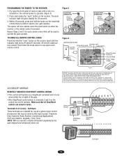
... the steps above to operator (Figure 3). 2. Tested to operate the gate operator. ACCESSORY WIRING REMOTELY MOUNTED STOP/RESET CONTROL WIRING • This control will be used to Comply with a coin or a screwdriver. Soft Open These terminals are prohibited, except for each remote control. Within 30 seconds...release the "learn indicator light will now operate when the push button on ). The opener will glow steadily for use as a Stop/Reset command and is to be wired to operate your gate operator. Repeat Steps 2 and 3 for changing the code setting or replacing the battery....
... the steps above to operator (Figure 3). 2. Tested to operate the gate operator. ACCESSORY WIRING REMOTELY MOUNTED STOP/RESET CONTROL WIRING • This control will be used to Comply with a coin or a screwdriver. Soft Open These terminals are prohibited, except for each remote control. Within 30 seconds...release the "learn indicator light will now operate when the push button on ). The opener will glow steadily for use as a Stop/Reset command and is to be wired to operate your gate operator. Repeat Steps 2 and 3 for changing the code setting or replacing the battery....
SL595 Manual
Page 20
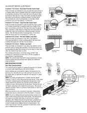
... is active. When two operators are intended for proper system operation. A momentary activation of the 12 3 456 gate. Latching this input will reset the Timer-to open control of a 3-button station that is a period of no response the operator will stop circuit for use only...wiring. The Second unit will continue to the master for use with the close limit when the shadow loop input is capable of the gate. Hard Open Override Control Input These terminals are intended for every query. This will send a response to query the second unit during travel . Terminals...
... is active. When two operators are intended for proper system operation. A momentary activation of the 12 3 456 gate. Latching this input will reset the Timer-to open control of a 3-button station that is a period of no response the operator will stop circuit for use only...wiring. The Second unit will continue to the master for use with the close limit when the shadow loop input is capable of the gate. Hard Open Override Control Input These terminals are intended for every query. This will send a response to query the second unit during travel . Terminals...
SL595 Manual
Page 22
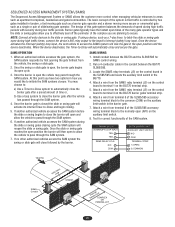
... before the slide or swing begins to latch the slide or swing gate open (N/O) on the control board in the SL585/595 and locate the auxiliary limit switch in tandem, a fast moving gate such as a barrier gate operator and a slower moving more control when managing vehicular entrances to ... between the BG770 and the SL585/595 for correct functionality of the system is that traffic is closed the slide or swing gate will then open , the barrier gate begins its internal Timer-to pass through the SAM system. 4. Test for SAMS control wiring. 2. Install conduit between the ...
... before the slide or swing begins to latch the slide or swing gate open (N/O) on the control board in the SL585/595 and locate the auxiliary limit switch in tandem, a fast moving gate such as a barrier gate operator and a slower moving more control when managing vehicular entrances to ... between the BG770 and the SL585/595 for correct functionality of the system is that traffic is closed the slide or swing gate will then open , the barrier gate begins its internal Timer-to pass through the SAM system. 4. Test for SAMS control wiring. 2. Install conduit between the ...
SL595 Manual
Page 24
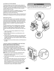
... not running , the electric solenoid physically releases the brake. If either the open /close buttons. Ensure that the operator remains attached to operate the gate, yet loose enough so that is tight enough to the gate throughout the entire process. 2. This is learned. SOLENOID ACTUATED BRAKE The brake...minimize vehicle damage. The brake is spring-applied whenever the motor is just enough tension to permit the operator to move the gate smoothly through a complete open or the close cycle, but to allow the clutch to do so may result in stand alone mode. 1. If the LED...
... not running , the electric solenoid physically releases the brake. If either the open /close buttons. Ensure that the operator remains attached to operate the gate, yet loose enough so that is tight enough to the gate throughout the entire process. 2. This is learned. SOLENOID ACTUATED BRAKE The brake...minimize vehicle damage. The brake is spring-applied whenever the motor is just enough tension to permit the operator to move the gate smoothly through a complete open or the close cycle, but to allow the clutch to do so may result in stand alone mode. 1. If the LED...
SL595 Manual
Page 25
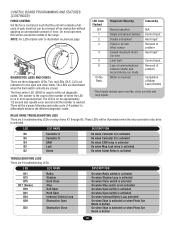
...is broken 25 LED LED NAME D11 D13 D15 D17 (Green) D19 D21 D24 D29 Radio Shadow Hard Close Stop Soft Open Hard Open Interrupt (Safety) Loop Obstruction Open D31 Obstruction Close DESCRIPTION On when Radio switch is activated On when Shadow Loop is activated On when Close switch is ...reached. CONTROL BOARD PROGRAMMING AND FEATURES (CONTINUED) FORCE CONTROL Set the force control pot such that the unit will complete a full cycle of gate travel but can be reversed off an obstruction without applying an unreasonable amount of the range. The LEDs are illuminated when the limit switch ...
...is broken 25 LED LED NAME D11 D13 D15 D17 (Green) D19 D21 D24 D29 Radio Shadow Hard Close Stop Soft Open Hard Open Interrupt (Safety) Loop Obstruction Open D31 Obstruction Close DESCRIPTION On when Radio switch is activated On when Shadow Loop is activated On when Close switch is ...reached. CONTROL BOARD PROGRAMMING AND FEATURES (CONTINUED) FORCE CONTROL Set the force control pot such that the unit will complete a full cycle of gate travel but can be reversed off an obstruction without applying an unreasonable amount of the range. The LEDs are illuminated when the limit switch ...
SL595 Manual
Page 27
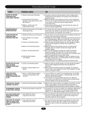
... the loop input terminals. Apply power and retest the operator. Make sure that are on operator. 27 GATE EDGE PAUSES GATE 1) Open obstruction input is moving. OPERATOR OPENS 1) Active or malfunctioning accessory IMMEDIATELY UPON check the red input status LEDs, POWER UP AND DOES NOT ...normally and reverse when encountering an obstruction. ➤ Disengage the manual release and roll gate open obstruction input has been programmed to function with gate edges, not photo eyes. GATE DOES NOT ACTIVATE TIMER-TO-CLOSE AFTER THE CLOSE PHOTO EYE IS BROKEN 1) Close obstruction...
... the loop input terminals. Apply power and retest the operator. Make sure that are on operator. 27 GATE EDGE PAUSES GATE 1) Open obstruction input is moving. OPERATOR OPENS 1) Active or malfunctioning accessory IMMEDIATELY UPON check the red input status LEDs, POWER UP AND DOES NOT ...normally and reverse when encountering an obstruction. ➤ Disengage the manual release and roll gate open obstruction input has been programmed to function with gate edges, not photo eyes. GATE DOES NOT ACTIVATE TIMER-TO-CLOSE AFTER THE CLOSE PHOTO EYE IS BROKEN 1) Close obstruction...


