
LiftMaster SL585 Sell Sheet Manual
Page 4
... breaks photo beam. Gate will continue to 120 seconds. MONITORED SAFETY INPUTS 3 Main Board, 3 Expansion Board. METAL FRAME 7-gauge pre-galvanized steel. Telephone Entry/ Access Control System (EL2000SS) High-capacity entry system. Includes factory installed heater. With optional heater (HTRNB: HTR460 for applications requiring a large number of the gate operator when the alarm has been activated. CHASSIS Heavy-duty steel chassis and lockable powdercoated steel cover...
... breaks photo beam. Gate will continue to 120 seconds. MONITORED SAFETY INPUTS 3 Main Board, 3 Expansion Board. METAL FRAME 7-gauge pre-galvanized steel. Telephone Entry/ Access Control System (EL2000SS) High-capacity entry system. Includes factory installed heater. With optional heater (HTRNB: HTR460 for applications requiring a large number of the gate operator when the alarm has been activated. CHASSIS Heavy-duty steel chassis and lockable powdercoated steel cover...

LiftMaster Gate Operator Feature Chart Manual
Page 2
... Slide Gate Operator Battery Backup Powers up when the 146 cycles 208 cycles 112 cycles - - - - Diagnostic Code Display2 Digit LED Yes Yes Yes Yes Yes Yes Yes Wireless Dual-Gate Operation Yes Yes Yes Yes Yes Yes Yes PosiLock® Feature - Yes Yes - - - - power's down Security+ 2.0® 3 Channel Receiver Virtually eliminates interference and extends range Yes Yes Yes Yes Yes Yes Yes UP TO 50 REMOTE CONTROL...
... Slide Gate Operator Battery Backup Powers up when the 146 cycles 208 cycles 112 cycles - - - - Diagnostic Code Display2 Digit LED Yes Yes Yes Yes Yes Yes Yes Wireless Dual-Gate Operation Yes Yes Yes Yes Yes Yes Yes PosiLock® Feature - Yes Yes - - - - power's down Security+ 2.0® 3 Channel Receiver Virtually eliminates interference and extends range Yes Yes Yes Yes Yes Yes Yes UP TO 50 REMOTE CONTROL...

SL585151U Installation Manual
Page 3
... POWER WIRING 17 DUAL GATES ONLY 20 ADJUST THE HANDING AND LIMITS 22 ADJUST THE CLUTCH 23 OBSTRUCTION TEST 24 OPERATOR OVERVIEW 25 CONTROL BOARD OVERVIEW 26 CONTROL BOARD REFERENCE 26 LEARN BUTTON 27 DIAGNOSTIC DISPLAY 27 HANDING BUTTONS 27 BIPART DELAY 27 TIMER-TO-CLOSE (TTC 27 FORCE DIAL 28 TEST BUTTONS 28 STATUS LEDS 28 WIRE ACCESSORIES TO CONTROL BOARD 29 THREE BUTTON CONTROL STATION 29 FIRE DEPARTMENT 29 LOOPS 29 PHOTOELECTRIC SENSORS AND EDGE SENSORS...
... POWER WIRING 17 DUAL GATES ONLY 20 ADJUST THE HANDING AND LIMITS 22 ADJUST THE CLUTCH 23 OBSTRUCTION TEST 24 OPERATOR OVERVIEW 25 CONTROL BOARD OVERVIEW 26 CONTROL BOARD REFERENCE 26 LEARN BUTTON 27 DIAGNOSTIC DISPLAY 27 HANDING BUTTONS 27 BIPART DELAY 27 TIMER-TO-CLOSE (TTC 27 FORCE DIAL 28 TEST BUTTONS 28 STATUS LEDS 28 WIRE ACCESSORIES TO CONTROL BOARD 29 THREE BUTTON CONTROL STATION 29 FIRE DEPARTMENT 29 LOOPS 29 PHOTOELECTRIC SENSORS AND EDGE SENSORS...
SL585151U Installation Manual
Page 5
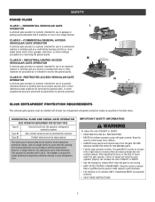
... DEATH. • Use the emergency release ONLY when the gate is for use separate entrance. • SAVE THESE INSTRUCTIONS. 3 however, a single device is not required to adjust and retest the gate operator properly can increase the risk of device shall not be installed with gate controls. Failure to cover both directions. UL325 ENTRAPMENT PROTECTION REQUIREMENTS This vehicular gate operator must be used for use in a commercial location or building such...
... DEATH. • Use the emergency release ONLY when the gate is for use separate entrance. • SAVE THESE INSTRUCTIONS. 3 however, a single device is not required to adjust and retest the gate operator properly can increase the risk of device shall not be installed with gate controls. Failure to cover both directions. UL325 ENTRAPMENT PROTECTION REQUIREMENTS This vehicular gate operator must be used for use in a commercial location or building such...

SL585151U Installation Manual
Page 6
... the gate operator. 8. The gate must take into public access areas. 7. Exception: Emergency access controls only accessible by a moving . e. The operator is specifically designed for the construction and the usage class of entrapment. Swinging gates shall not open position. One or more contact sensors shall be located at the leading edge, trailing edge and post mounted both directions prior to the installation of travel , one that the gate covers...
... the gate operator. 8. The gate must take into public access areas. 7. Exception: Emergency access controls only accessible by a moving . e. The operator is specifically designed for the construction and the usage class of entrapment. Swinging gates shall not open position. One or more contact sensors shall be located at the leading edge, trailing edge and post mounted both directions prior to the installation of travel , one that the gate covers...

SL585151U Installation Manual
Page 7
... operator requires replacement, shall be upgraded to conform to the provisions of this specification in question. 5 These stops shall be installed at either the top of the gate, or at 610-832-9585 or www.astm.org. 1. The gate panel shall include the entire section of the moving vehicular access gate. SAFETY GATE CONSTRUCTION INFORMATION Vehicular gates should be installed in accordance with a moving gate,including any gate...
... operator requires replacement, shall be upgraded to conform to the provisions of this specification in question. 5 These stops shall be installed at either the top of the gate, or at 610-832-9585 or www.astm.org. 1. The gate panel shall include the entire section of the moving vehicular access gate. SAFETY GATE CONSTRUCTION INFORMATION Vehicular gates should be installed in accordance with a moving gate,including any gate...

SL585151U Installation Manual
Page 14
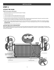
... with the lower mounting angles configured out (Figure 1). INSTALLATION STEP 1 INSTALL THE OPERATOR Check the national and local building codes before installation. Secure operator to the concrete pad using four 1/2" concrete anchors (not provided). 4" (10.2 cm) (Gate) 1" (2.5 cm) (Conduit Location) 36" (91.4 cm) Drive and idler sprocket toward gate side 18" (45.7 cm) 1/2" Concrete Anchors (4 Required) 2" to 4" (5.1 to 10.2 cm) Above Grade Power and Control Wiring Must Be...
... with the lower mounting angles configured out (Figure 1). INSTALLATION STEP 1 INSTALL THE OPERATOR Check the national and local building codes before installation. Secure operator to the concrete pad using four 1/2" concrete anchors (not provided). 4" (10.2 cm) (Gate) 1" (2.5 cm) (Conduit Location) 36" (91.4 cm) Drive and idler sprocket toward gate side 18" (45.7 cm) 1/2" Concrete Anchors (4 Required) 2" to 4" (5.1 to 10.2 cm) Above Grade Power and Control Wiring Must Be...
SL585151U Installation Manual
Page 16
.... Thread the chain through the plastic chain guide, around drive and idler sprockets, and then through the second plastic chain guide toward front gate bracket. 6. Rear Gate Bracket Manual Release Handle 14 Front Gate Bracket Chain Guide Adjust the chain to proper length and connect the chain to remove chain slack. A general rule of thumb is tightened. Remove the operator cover. 3. Locate and engage the manual release handle and lock it in line with bottom of the gate. 2. Connect the chain to leave...
.... Thread the chain through the plastic chain guide, around drive and idler sprockets, and then through the second plastic chain guide toward front gate bracket. 6. Rear Gate Bracket Manual Release Handle 14 Front Gate Bracket Chain Guide Adjust the chain to proper length and connect the chain to remove chain slack. A general rule of thumb is tightened. Remove the operator cover. 3. Locate and engage the manual release handle and lock it in line with bottom of the gate. 2. Connect the chain to leave...
SL585151U Installation Manual
Page 18
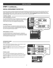
... sensed OPEN CLOSE TO MAIN BOARD Photoelectric Sensors 1 EYE ONLY 2 EYE/ EDGE 3 EYE/ EDGE COM SBC OPN + Photoelectric Sensors OR + Edge Sensor + - INSTALLATION STEP 3 continued... Only one monitored entrapment protection device may be wired to the expansion board. This input will function. BIPART DELAY 4 2 6 OPEN LEFT OPEN 8 RIGHT HANDING COMM LINK BA CLASS 2 SUPPLY 24 VAC 500 mA MAX GND ANTENNA CURRENT MOTOR DRIVE SENSOR ID RESET RPM & LIMITS ALARM EXP. INSTALL ENTRAPMENT...
... sensed OPEN CLOSE TO MAIN BOARD Photoelectric Sensors 1 EYE ONLY 2 EYE/ EDGE 3 EYE/ EDGE COM SBC OPN + Photoelectric Sensors OR + Edge Sensor + - INSTALLATION STEP 3 continued... Only one monitored entrapment protection device may be wired to the expansion board. This input will function. BIPART DELAY 4 2 6 OPEN LEFT OPEN 8 RIGHT HANDING COMM LINK BA CLASS 2 SUPPLY 24 VAC 500 mA MAX GND ANTENNA CURRENT MOTOR DRIVE SENSOR ID RESET RPM & LIMITS ALARM EXP. INSTALL ENTRAPMENT...

SL585151U Installation Manual
Page 22
... PrOopuetsritdye 20 All wireless accessories will light. 6. Press and release the LEARN button again on the same operator. The green XMITTER LED will need to be programmed to be the network primary operator. Press and release the LEARN button again on the primary operator. BIPART DELAY 4 2 6 OPEN LEFT OPEN 8 RIGHT HANDING OPEN GND ANTENNA CURRENT MOTOR DRIVE SENSOR ID RESET RPM & LIMITS ALARM EXP. Press and release the OPEN test button to assign this operator as network primary...
... PrOopuetsritdye 20 All wireless accessories will light. 6. Press and release the LEARN button again on the same operator. The green XMITTER LED will need to be programmed to be the network primary operator. Press and release the LEARN button again on the primary operator. BIPART DELAY 4 2 6 OPEN LEFT OPEN 8 RIGHT HANDING OPEN GND ANTENNA CURRENT MOTOR DRIVE SENSOR ID RESET RPM & LIMITS ALARM EXP. Press and release the OPEN test button to assign this operator as network primary...

SL585151U Installation Manual
Page 24
... minimum amount required to move gate. • NEVER use force adjustments to compensate for a binding or sticking gate. • If one full cycle using the FORCE dial on the control board (refer to Force Dial section). SET THE HANDING 1. Press and release the CLOSE test button to open . SET THE FORCE AND RUN DISTANCE 1. Press the OPEN test button to close position. Press and release both handing LEDs start to flash and the operator beeps. 2.
... minimum amount required to move gate. • NEVER use force adjustments to compensate for a binding or sticking gate. • If one full cycle using the FORCE dial on the control board (refer to Force Dial section). SET THE HANDING 1. Press and release the CLOSE test button to open . SET THE FORCE AND RUN DISTANCE 1. Press the OPEN test button to close position. Press and release both handing LEDs start to flash and the operator beeps. 2.

SL585151U Installation Manual
Page 26
... ANTENNA CURRENT MOTOR DRIVE SENSOR ID RESET RPM & LIMITS ALARM EXP. Ensure that the gate is equipped with a solid object. 4. The gate should stop the gate. Run the gate in the close limits, but MUST reverse after contact with an automatic obstruction sensing feature. After any adjustments are made, test the operator: 1. If the gate does not reverse off the solid object, reduce the force setting by turning the force control slightly counter-clockwise. INSTALLATION...
... ANTENNA CURRENT MOTOR DRIVE SENSOR ID RESET RPM & LIMITS ALARM EXP. Ensure that the gate is equipped with a solid object. 4. The gate should stop the gate. Run the gate in the close limits, but MUST reverse after contact with an automatic obstruction sensing feature. After any adjustments are made, test the operator: 1. If the gate does not reverse off the solid object, reduce the force setting by turning the force control slightly counter-clockwise. INSTALLATION...

SL585151U Installation Manual
Page 29
... from the open controls, loops, close edges, and close photoelectric sensors. 0 seconds (OFF) The gate will close limit when opening . For more information about the codes refer to 180 seconds). OPEN LEFT OPEN RIGHT HANDING OPEN LEFT If the operator is installed on the control board prior to the Adjustment section). The TTC is factory set the limits (refer to the TTC expiring will remain open and they are also used for programming (refer to...
... from the open controls, loops, close edges, and close photoelectric sensors. 0 seconds (OFF) The gate will close limit when opening . For more information about the codes refer to 180 seconds). OPEN LEFT OPEN RIGHT HANDING OPEN LEFT If the operator is installed on the control board prior to the Adjustment section). The TTC is factory set the limits (refer to the TTC expiring will remain open and they are also used for programming (refer to...

SL585151U Installation Manual
Page 38
... the instructions, may cause harmful interference to radio communications. The operator will automatically exit learn mode (operator will beep and green XMITTER LED will light). NOTICE: This device complies with part 15 of the FCC rules. When programming a third keyless entry to the operator, the first keyless entry will need to be set to close the gate. PROGRAMMING STEPS 1. Any changes or modifications not expressly approved by one remote control button as OPEN, CLOSE, and STOP DESCRIPTION Program a single button on...
... the instructions, may cause harmful interference to radio communications. The operator will automatically exit learn mode (operator will beep and green XMITTER LED will light). NOTICE: This device complies with part 15 of the FCC rules. When programming a third keyless entry to the operator, the first keyless entry will need to be set to close the gate. PROGRAMMING STEPS 1. Any changes or modifications not expressly approved by one remote control button as OPEN, CLOSE, and STOP DESCRIPTION Program a single button on...
SL585151U Installation Manual
Page 42
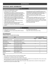
... force or the limit of travel . • SAVE THESE INSTRUCTIONS. For continued protection against fire and electrocution: • DISCONNECT power (AC or solar and battery) BEFORE installing or servicing operator. Never use only lithium spray. To tighten the drive chain adjust either of same type and rating. Keep the remote control away from children. • ALWAYS keep people and objects away from the gate. The gate MUST reverse...
... force or the limit of travel . • SAVE THESE INSTRUCTIONS. For continued protection against fire and electrocution: • DISCONNECT power (AC or solar and battery) BEFORE installing or servicing operator. Never use only lithium spray. To tighten the drive chain adjust either of same type and rating. Keep the remote control away from children. • ALWAYS keep people and objects away from the gate. The gate MUST reverse...
SL585151U Installation Manual
Page 44
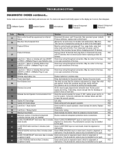
... powered, deactivate the wireless feature and then re-learn the second operator. System AC Undervoltage Check wiring and wire gauge to force a fresh boot. Replace if defective. Review monitored entrapment protection device connections. CLOSE EDGE held more than 3 minutes (expansion board) Check wired input on the display as it will briefly appear on expansion board; Some codes are saved in the loop, or OPEN - LiftMaster System Installed System Informational External...
... powered, deactivate the wireless feature and then re-learn the second operator. System AC Undervoltage Check wiring and wire gauge to force a fresh boot. Replace if defective. Review monitored entrapment protection device connections. CLOSE EDGE held more than 3 minutes (expansion board) Check wired input on the display as it will briefly appear on expansion board; Some codes are saved in the loop, or OPEN - LiftMaster System Installed System Informational External...

SL585151U Installation Manual
Page 45
... operator wired bus or radio. May have to the main control board. Force Reversal Look for an obstructed gate, binding in the code history and some are NOT moving, or moving , failure is engaged and free to erase the wireless communication and reprogram the two operators. CLOSE EYE/INTERRUPT triggered, causing IF an obstruction occurred, no obstruction, check that the operator is engaged and free to move . LiftMaster...
... operator wired bus or radio. May have to the main control board. Force Reversal Look for an obstructed gate, binding in the code history and some are NOT moving, or moving , failure is engaged and free to erase the wireless communication and reprogram the two operators. CLOSE EYE/INTERRUPT triggered, causing IF an obstruction occurred, no obstruction, check that the operator is engaged and free to move . LiftMaster...
SL585151U Installation Manual
Page 47
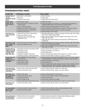
... to move to a limit position b) Gate is a normally closed circuit, or put a jumper on . Gate closes, but motor does not run and b) Open fuse diagnostics display not on the stop and reverse. b) Replace defective Exit loop detector. a) Review Interrupt loop detector settings. a) Gate does not move c) Limits are set correct limits. SOLUTIONS a) Check AC power b) Check fuses c) Replace defective control board a) Check reset switch b) Check Stop button is not "stuck on " detector a) Activate wireless control and check XMITTER LED is stuck b) Stop button active or jumper not...
... to move to a limit position b) Gate is a normally closed circuit, or put a jumper on . Gate closes, but motor does not run and b) Open fuse diagnostics display not on the stop and reverse. b) Replace defective Exit loop detector. a) Review Interrupt loop detector settings. a) Gate does not move c) Limits are set correct limits. SOLUTIONS a) Check AC power b) Check fuses c) Replace defective control board a) Check reset switch b) Check Stop button is not "stuck on " detector a) Activate wireless control and check XMITTER LED is stuck b) Stop button active or jumper not...
SL585151U Installation Manual
Page 48
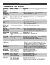
...Expansion board function not controlling gate. a) Check that opens first) a) Pre-warning is set to "ON" b) Constant pressure to open limit. a) Vehicle detector setup incorrectly b) Defective vehicle loop detector Obstruction in a) Force adjustment needed . On dual-gate system, incorrect gate opens first or closes first. Press the reset button to stop and reverse Photoelectric sensor does not stop or reverse b) Defective edge sensor gate. and COM terminals. TROUBLESHOOTING TROUBLESHOOTING CHART continued... a) Check edge sensor wiring. Quick Close not working...
...Expansion board function not controlling gate. a) Check that opens first) a) Pre-warning is set to "ON" b) Constant pressure to open limit. a) Vehicle detector setup incorrectly b) Defective vehicle loop detector Obstruction in a) Force adjustment needed . On dual-gate system, incorrect gate opens first or closes first. Press the reset button to stop and reverse Photoelectric sensor does not stop or reverse b) Defective edge sensor gate. and COM terminals. TROUBLESHOOTING TROUBLESHOOTING CHART continued... a) Check edge sensor wiring. Quick Close not working...
SL585151U Installation Manual
Page 51
... to you . THIS LIMITED WARRANTY DOES NOT COVER NON-DEFECT DAMAGE, DAMAGE CAUSED BY IMPROPER INSTALLATION, OPERATION OR CARE (INCLUDING, BUT NOT LIMITED TO ABUSE, MISUSE, FAILURE TO PROVIDE REASONABLE AND NECESSARY MAINTENANCE, UNAUTHORIZED REPAIRS OR ANY ALTERATIONS TO THIS PRODUCT), LABOR CHARGES FOR REINSTALLING A REPAIRED OR REPLACED UNIT, OR REPLACEMENT OF BATTERIES. Some states do not allow limitations on your compliance with...
... to you . THIS LIMITED WARRANTY DOES NOT COVER NON-DEFECT DAMAGE, DAMAGE CAUSED BY IMPROPER INSTALLATION, OPERATION OR CARE (INCLUDING, BUT NOT LIMITED TO ABUSE, MISUSE, FAILURE TO PROVIDE REASONABLE AND NECESSARY MAINTENANCE, UNAUTHORIZED REPAIRS OR ANY ALTERATIONS TO THIS PRODUCT), LABOR CHARGES FOR REINSTALLING A REPAIRED OR REPLACED UNIT, OR REPLACEMENT OF BATTERIES. Some states do not allow limitations on your compliance with...


