Owners Manual
Page 3
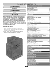
... External Loop Detector Wiring 22 Entrapment Protection Devices (Contact Sensors 23 Entrapment Protection Devices (Non-Contact Sensors 24 Omni Option Board Connections (Optional 25 ADJUSTMENTS Set Gate Opening Direction 26 Limit Switch Adjustments 26 315 MHz 24Vdc Radio Receiver Programming 27-28 Setting the Timer (On, Off 29 Adjusting Reversing Sensor(s 30 MAINTENANCE AND OPERATION Maintenance 31 OPERATION Built-In Reset Switch 32 Audio Alarm 32 EMERGENCY MANUAL RELEASE 33 ACCESSORIES 34 WIRING DIAGRAMS 35-42 TROUBLESHOOTING 43-44 REPAIR PARTS Repair Part Illustrations...
... External Loop Detector Wiring 22 Entrapment Protection Devices (Contact Sensors 23 Entrapment Protection Devices (Non-Contact Sensors 24 Omni Option Board Connections (Optional 25 ADJUSTMENTS Set Gate Opening Direction 26 Limit Switch Adjustments 26 315 MHz 24Vdc Radio Receiver Programming 27-28 Setting the Timer (On, Off 29 Adjusting Reversing Sensor(s 30 MAINTENANCE AND OPERATION Maintenance 31 OPERATION Built-In Reset Switch 32 Audio Alarm 32 EMERGENCY MANUAL RELEASE 33 ACCESSORIES 34 WIRING DIAGRAMS 35-42 TROUBLESHOOTING 43-44 REPAIR PARTS Repair Part Illustrations...
Owners Manual
Page 6
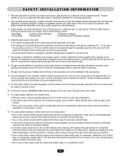
Install the gate operator only when: a. The pedestrian access opening shall be incorporated into every design. Swinging gates shall not open position. The Stop and/or Reset (if provided separately) must be designed to the installation of the gate. c. b. SAFETY INSTALLATION INFORMATION 1. Gate operating system designers, installers and users must be located in a location so that enough clearance is supplied between the sensor and the gate operator is greater than 6" (152 mm) above the...
Install the gate operator only when: a. The pedestrian access opening shall be incorporated into every design. Swinging gates shall not open position. The Stop and/or Reset (if provided separately) must be designed to the installation of the gate. c. b. SAFETY INSTALLATION INFORMATION 1. Gate operating system designers, installers and users must be located in a location so that enough clearance is supplied between the sensor and the gate operator is greater than 6" (152 mm) above the...
Owners Manual
Page 7
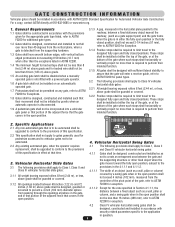
... that time. 3. Specific Applications 2.1 Any non-automated gate that the gate will enter a receiver guide, refer to ASTM F2200 for panel types. 3.2 The following provisions shall apply to Class IV vehicular horizontal slide gates: 3.2.1 All weight bearing exposed rollers 8 feet (2.44 m), or less, above grade shall be guarded or covered. 3.2.2 Positive stops shall be required to limit travel to the designed fully open...
... that time. 3. Specific Applications 2.1 Any non-automated gate that the gate will enter a receiver guide, refer to ASTM F2200 for panel types. 3.2 The following provisions shall apply to Class IV vehicular horizontal slide gates: 3.2.1 All weight bearing exposed rollers 8 feet (2.44 m), or less, above grade shall be guarded or covered. 3.2.2 Positive stops shall be required to limit travel to the designed fully open...
Owners Manual
Page 15
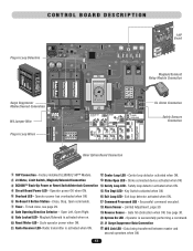
.... 6 On-Board 3 Button Station - See page 30. 9 Gate Locked LED - Safety loop detector activated when ON. 4 Circuit Board Power LED - Operator power OK when ON. 15 Fire Dept LED - Gate hit obstruction when ON. Cycle operator power when ON. 21 J1 Surge Suppressor Data Connection 11 Radio Receiver LED- Data being transferred between master and second operators when ON. 13 Limited Adjustment, page 30. 8 Gate Opening Direction Selector - CONTROL BOARD DESCRIPTION Plug-In Loop Detectors CENTER SAFETY EXIT 1 HP Board 1 Maglock/Solenoid Relay Module Connection Not Used Surge...
.... 6 On-Board 3 Button Station - See page 30. 9 Gate Locked LED - Safety loop detector activated when ON. 4 Circuit Board Power LED - Operator power OK when ON. 15 Fire Dept LED - Gate hit obstruction when ON. Cycle operator power when ON. 21 J1 Surge Suppressor Data Connection 11 Radio Receiver LED- Data being transferred between master and second operators when ON. 13 Limited Adjustment, page 30. 8 Gate Opening Direction Selector - CONTROL BOARD DESCRIPTION Plug-In Loop Detectors CENTER SAFETY EXIT 1 HP Board 1 Maglock/Solenoid Relay Module Connection Not Used Surge...
Owners Manual
Page 19
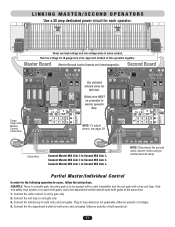
... DEPT. STRIKE OPEN RADIO RECEIVER GATE LOCKED EXIT LOOP SAFETY LOOP CENTER LOOP RESET MOTOR CLOSE STOP OPEN POWER OVERLOAD MADE IN USA ® OmniControl Surge SuppressorPatenPt /PNenQd4in1g0 SENSOR ALARM CHASSIS GROUND G BA M/S Link - + Center Loop Safety Loop Exit Fire Dept Strike Open Loop Key Switch Push Button Radio Receiver CHASSIS GROUND Shield Wire Connect Master M/S Link G to link operators together. Connect the fire department switch to occur, follow the instructions. LINKING MASTER/SECOND OPERATORS Use a 20 amp dedicated power circuit for each operator. Run...
... DEPT. STRIKE OPEN RADIO RECEIVER GATE LOCKED EXIT LOOP SAFETY LOOP CENTER LOOP RESET MOTOR CLOSE STOP OPEN POWER OVERLOAD MADE IN USA ® OmniControl Surge SuppressorPatenPt /PNenQd4in1g0 SENSOR ALARM CHASSIS GROUND G BA M/S Link - + Center Loop Safety Loop Exit Fire Dept Strike Open Loop Key Switch Push Button Radio Receiver CHASSIS GROUND Shield Wire Connect Master M/S Link G to link operators together. Connect the fire department switch to occur, follow the instructions. LINKING MASTER/SECOND OPERATORS Use a 20 amp dedicated power circuit for each operator. Run...
Owners Manual
Page 21
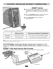
... Push Button", "Key Switch", "Photoelectric Sensor" or "Edge Sensor" will cancel the automatic mode of the DC2000™. Socket Reset button and interlock wires, Do Not Remove. 120Vac Power Failure Manual Mode Push and Hold to operate gate. CLASS I, II, III, IV Make sure "Gate Direction" setting on , the battery needs to operate in the 12 pin plug into the DC2000™ control unit. Auto Mode Gate automatically opens. 120Vac Power On, OmniControl™ Board Malfunction Turn the 120Vac power off then gate opens...
... Push Button", "Key Switch", "Photoelectric Sensor" or "Edge Sensor" will cancel the automatic mode of the DC2000™. Socket Reset button and interlock wires, Do Not Remove. 120Vac Power Failure Manual Mode Push and Hold to operate gate. CLASS I, II, III, IV Make sure "Gate Direction" setting on , the battery needs to operate in the 12 pin plug into the DC2000™ control unit. Auto Mode Gate automatically opens. 120Vac Power On, OmniControl™ Board Malfunction Turn the 120Vac power off then gate opens...
Owners Manual
Page 22
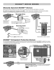
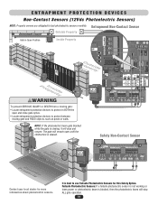
...-BACKUP ALARM SENSOR SYSTEM ON SENSORS 1 3 1 3 REVERSE SENSOR TIMER 60 3 OFF OPEN LEFT 1 3 ON OPEN RIGHT COMMAND PROCESSED FIRE DEPT. Manual One-Button 1234567 See Accessories 1234567 Reset button and interlock wires, Do Not Remove. Push button again and HOLD to Close. 1234567 Manual Key Switch See Accessories Turn and HOLD key to operate. Contact your local Fire/Police municipalities for property owner's emergency access ONLY. Turn key again and HOLD to Open. The entrapment protection devices connected to maintain gate safety...
...-BACKUP ALARM SENSOR SYSTEM ON SENSORS 1 3 1 3 REVERSE SENSOR TIMER 60 3 OFF OPEN LEFT 1 3 ON OPEN RIGHT COMMAND PROCESSED FIRE DEPT. Manual One-Button 1234567 See Accessories 1234567 Reset button and interlock wires, Do Not Remove. Push button again and HOLD to Close. 1234567 Manual Key Switch See Accessories Turn and HOLD key to operate. Contact your local Fire/Police municipalities for property owner's emergency access ONLY. Turn key again and HOLD to Open. The entrapment protection devices connected to maintain gate safety...

Owners Manual
Page 23
...STRIKE OPEN RADIO RECEIVER GATE LOCKED EXIT LOOP SAFETY LOOP CENTER LOOP RESET MOTOR CLOSE STOP OPEN POWER OVERLOAD MADE IN USA CAUTION Outside Safety Loop To AVOID damaging control board, disconnect ALL power to operator before installing plug-in loop detectors. 21 Use a different frequency for vehicles 14 feet or longer. Plug-In "Safety" Loop Detector - Caution: Suggested for every loop detector installed. Example of a 3 wire turn loop connected in loop detector manual for more specific information. Allows gate to automatically open when vehicles are connected...
...STRIKE OPEN RADIO RECEIVER GATE LOCKED EXIT LOOP SAFETY LOOP CENTER LOOP RESET MOTOR CLOSE STOP OPEN POWER OVERLOAD MADE IN USA CAUTION Outside Safety Loop To AVOID damaging control board, disconnect ALL power to operator before installing plug-in loop detectors. 21 Use a different frequency for vehicles 14 feet or longer. Plug-In "Safety" Loop Detector - Caution: Suggested for every loop detector installed. Example of a 3 wire turn loop connected in loop detector manual for more specific information. Allows gate to automatically open when vehicles are connected...
Owners Manual
Page 26
... GBA MS LINK ALARM SENSOR DC-BACKUP SYSTEM ON SENSORS 1 3 1 3 REVERSE SENSOR TIMER 60 3 OFF OPEN LEFT 1 3 ON OPEN RIGHT COMMAND PROCESSED FIRE DEPT. STRIKE OPEN RADIO RECEIVER GATE LOCKED EXIT LOOP SAFETY LOOP CENTER LOOP RESET MOTOR CLOSE STOP OPEN POWER OVERLOAD MADE IN USA SENSOR ALARM CENTER SAFETY EXIT GBA ® OmniControl Surge Suppressor P/N Q410 Patent Pending 1 234 56 7 8 9 10 11 12 13 G BA M/S Link - + Center Loop Safety Loop Exit Fire Dept Strike Open Loop Key Switch Push Button Radio Receiver NOTE: If the photoelectric beam gets...
... GBA MS LINK ALARM SENSOR DC-BACKUP SYSTEM ON SENSORS 1 3 1 3 REVERSE SENSOR TIMER 60 3 OFF OPEN LEFT 1 3 ON OPEN RIGHT COMMAND PROCESSED FIRE DEPT. STRIKE OPEN RADIO RECEIVER GATE LOCKED EXIT LOOP SAFETY LOOP CENTER LOOP RESET MOTOR CLOSE STOP OPEN POWER OVERLOAD MADE IN USA SENSOR ALARM CENTER SAFETY EXIT GBA ® OmniControl Surge Suppressor P/N Q410 Patent Pending 1 234 56 7 8 9 10 11 12 13 G BA M/S Link - + Center Loop Safety Loop Exit Fire Dept Strike Open Loop Key Switch Push Button Radio Receiver NOTE: If the photoelectric beam gets...
Owners Manual
Page 27
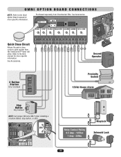
... OPEN LEFT 1 3 ON OPEN RIGHT COMMAND PROCESSED FIRE DEPT. QCC A B OPEN STOP CLOSE MAGLOCK ALARM ARMED M/S LINK W4 Quick Close Circuit Allows the gate's close cycle to close quicker than the OmniControl™ timer will allow. STRIKE OPEN RADIO RECEIVER GATE LOCKED EXIT LOOP SAFETY LOOP CENTER LOOP RESET MOTOR CLOSE STOP OPEN POWER OVERLOAD MADE IN USA W4 G Relay Contact Rating 0.5 Amp - 125Vac 1 Amp - 24Vdc Maglock Solenoid Lock 25 OMNI OPTION BOARD CONNECTIONS NOTE: Refer to the Omni Option Board manual for more specific information...
... OPEN LEFT 1 3 ON OPEN RIGHT COMMAND PROCESSED FIRE DEPT. QCC A B OPEN STOP CLOSE MAGLOCK ALARM ARMED M/S LINK W4 Quick Close Circuit Allows the gate's close cycle to close quicker than the OmniControl™ timer will allow. STRIKE OPEN RADIO RECEIVER GATE LOCKED EXIT LOOP SAFETY LOOP CENTER LOOP RESET MOTOR CLOSE STOP OPEN POWER OVERLOAD MADE IN USA W4 G Relay Contact Rating 0.5 Amp - 125Vac 1 Amp - 24Vdc Maglock Solenoid Lock 25 OMNI OPTION BOARD CONNECTIONS NOTE: Refer to the Omni Option Board manual for more specific information...
Owners Manual
Page 28
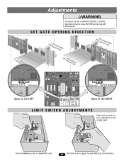
...ON SENSOR ALARM RADIO Open to adjust the open and close limit switches. Push and hold lock plate to release limit nuts. 26 Roll limit nuts to the LEFT W4 G B A MS LINK ALARM SENSOR DC-BACKUP SYSTEM ON SENSORS 1 3 1 3 REVERSE SENSOR TIMER 60 3 OFF OPEN LEFT 1 3 ON OPEN RIGHT COMMAND PROCESSED FIRE DEPT. Adjustments WARNING To reduce the risk of gate travel. STRIKE OPEN RADIO RECEIVER GATE LOCKED EXIT LOOP SAFETY LOOP CENTER LOOP RESET MOTOR CLOSE STOP OPEN POWER OVERLOAD MADE IN USA RADIO Open to the RIGHT CENTER SAFETY EXIT LIMIT SWITCH ADJUSTMENTS...
...ON SENSOR ALARM RADIO Open to adjust the open and close limit switches. Push and hold lock plate to release limit nuts. 26 Roll limit nuts to the LEFT W4 G B A MS LINK ALARM SENSOR DC-BACKUP SYSTEM ON SENSORS 1 3 1 3 REVERSE SENSOR TIMER 60 3 OFF OPEN LEFT 1 3 ON OPEN RIGHT COMMAND PROCESSED FIRE DEPT. Adjustments WARNING To reduce the risk of gate travel. STRIKE OPEN RADIO RECEIVER GATE LOCKED EXIT LOOP SAFETY LOOP CENTER LOOP RESET MOTOR CLOSE STOP OPEN POWER OVERLOAD MADE IN USA RADIO Open to the RIGHT CENTER SAFETY EXIT LIMIT SWITCH ADJUSTMENTS...
Owners Manual
Page 29
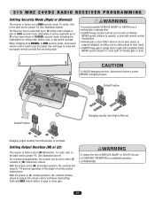
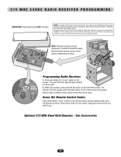
... remote control transmitters. • Activate gate or door ONLY when it can be seen clearly, is properly adjusted, and there are being used with up to jumper P4 (See illustration below). 315 MHZ 24VDC RADIO RECEIVER PROGRAMMING Setting Security Mode (High) or (Normal): The receiver is factory set at (M) Momentary. To verify, refer to the label next to 15 rolling code remotes or pins in sight until completely closed...
... remote control transmitters. • Activate gate or door ONLY when it can be seen clearly, is properly adjusted, and there are being used with up to jumper P4 (See illustration below). 315 MHZ 24VDC RADIO RECEIVER PROGRAMMING Setting Security Mode (High) or (Normal): The receiver is factory set at (M) Momentary. To verify, refer to the label next to 15 rolling code remotes or pins in sight until completely closed...
Owners Manual
Page 30
... device may cause undesired operation. NOTE: Receiver wiring on the receiver. 315 MHZ 24VDC RADIO RECEIVER PROGRAMMING IMPORTANT: Hand-held remote. Erase ALL Remote Control Codes: Press and hold the button on the receiver panel until the indicator light turns off (about 6 seconds). Operation is pressed. Optional 315 MHz Hand Held Remotes - The operator will glow steadily for changing the code setting or replacing the battery. Press and release the "Learn" button on Surge Suppressor Terminal Connections page.
... device may cause undesired operation. NOTE: Receiver wiring on the receiver. 315 MHZ 24VDC RADIO RECEIVER PROGRAMMING IMPORTANT: Hand-held remote. Erase ALL Remote Control Codes: Press and hold the button on the receiver panel until the indicator light turns off (about 6 seconds). Operation is pressed. Optional 315 MHz Hand Held Remotes - The operator will glow steadily for changing the code setting or replacing the battery. Press and release the "Learn" button on Surge Suppressor Terminal Connections page.
Owners Manual
Page 32
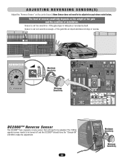
...control board. ADJUSTING REVERSING SENSOR(S) Adjust the "Reverse Sensor" on the weight of the gate and the condition of installation. Sensor is set sensitive enough = if the gate hits an object and does not stop or reverse. 3 1 3 Maximum Sensitivity CENTER SAFETY EXIT SENSOR ALARM Minimum Sensitivity W4 G B A MS LINK ALARM SENSOR DC-BACKUP SYSTEM ON SENSORS 1 3 1 3 REVERSE SENSOR TIMER 60 3 OFF OPEN LEFT 1 3 ON OPEN RIGHT COMMAND PROCESSED FIRE DEPT. STRIKE OPEN RADIO RECEIVER GATE LOCKED EXIT LOOP SAFETY LOOP CENTER LOOP RESET MOTOR CLOSE STOP OPEN POWER...
...control board. ADJUSTING REVERSING SENSOR(S) Adjust the "Reverse Sensor" on the weight of the gate and the condition of installation. Sensor is set sensitive enough = if the gate hits an object and does not stop or reverse. 3 1 3 Maximum Sensitivity CENTER SAFETY EXIT SENSOR ALARM Minimum Sensitivity W4 G B A MS LINK ALARM SENSOR DC-BACKUP SYSTEM ON SENSORS 1 3 1 3 REVERSE SENSOR TIMER 60 3 OFF OPEN LEFT 1 3 ON OPEN RIGHT COMMAND PROCESSED FIRE DEPT. STRIKE OPEN RADIO RECEIVER GATE LOCKED EXIT LOOP SAFETY LOOP CENTER LOOP RESET MOTOR CLOSE STOP OPEN POWER...
Owners Manual
Page 38
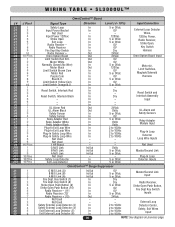
... 0Vdc - 5 or 0Vdc 5 or 0Vdc Input Connection External Loop Detector Wires, 120Vac Power, Radio Receiver, Strike Open, Key Switch Harness Omni Option Board Input Motor(s), Limit Switches, Maglock/Solenoid Harness Reset Switch and Interlock Assembly Input UL Alarm and Safety Sensors Relay Adapter Module Input Plug-In Loop Detector Loop Wire Inputs Not Used Master/Second Link Plug-In Loop Detector Inputs OmniControl™ Surge Suppressor G M/S Link (G) B M/S Link (B) A M/S Link (A) Fire Dept. Reset Switch, Interlock Red - Dry - Reset Switch, Interlock Black - - - Dry - - - 24Vdc 0Vdc...
... 0Vdc - 5 or 0Vdc 5 or 0Vdc Input Connection External Loop Detector Wires, 120Vac Power, Radio Receiver, Strike Open, Key Switch Harness Omni Option Board Input Motor(s), Limit Switches, Maglock/Solenoid Harness Reset Switch and Interlock Assembly Input UL Alarm and Safety Sensors Relay Adapter Module Input Plug-In Loop Detector Loop Wire Inputs Not Used Master/Second Link Plug-In Loop Detector Inputs OmniControl™ Surge Suppressor G M/S Link (G) B M/S Link (B) A M/S Link (A) Fire Dept. Reset Switch, Interlock Red - Dry - Reset Switch, Interlock Black - - - Dry - - - 24Vdc 0Vdc...
Owners Manual
Page 40
...Master/Second Link Input Radio Receiver, Strike Open Push Button, Fire Dept Key Switch Inputs External Loop Detector Center, Safety, Exit Wires Input 38 NOTE: See diagram on previous page. Reset Switch, Interlock Red - Key Switch (7) Fire Dept. Radio Receiver Fire Dept Key Switch Radio Receiver + Omni Option Board Limit Switch Red N.O. Reset Switch, Interlock Black - - - UL Alarm Red UL Alarm Black Safety Sensor Safety Sensor Relay Adapter Red Relay Adapter White Relay Adapter Black Plug-In Exit Loop Wire Plug-In Exit Loop Wire Plug-In Safety Loop Wire Plug-In Safety Loop Wire Not Used...
...Master/Second Link Input Radio Receiver, Strike Open Push Button, Fire Dept Key Switch Inputs External Loop Detector Center, Safety, Exit Wires Input 38 NOTE: See diagram on previous page. Reset Switch, Interlock Red - Key Switch (7) Fire Dept. Radio Receiver Fire Dept Key Switch Radio Receiver + Omni Option Board Limit Switch Red N.O. Reset Switch, Interlock Black - - - UL Alarm Red UL Alarm Black Safety Sensor Safety Sensor Relay Adapter Red Relay Adapter White Relay Adapter Black Plug-In Exit Loop Wire Plug-In Exit Loop Wire Plug-In Safety Loop Wire Plug-In Safety Loop Wire Not Used...
Owners Manual
Page 42
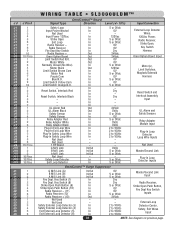
...Safety Sensors Relay Adapter Module Input Plug-In Loop Detector Loop Wire Inputs 1 HP Board Input Master/Second Link Plug-In Loop Detector Inputs Motor Red Motor Black Motor White Neutral - Key Switch (7) Fire Dept. Out Out 0V 120Vac 0V - 120Vac 0V 2 Motors Input OmniControl™ Surge Suppressor G M/S Link (G) B M/S Link (B) A M/S Link (A) Fire Dept. Dry - Not Used - Limit Switch Brown Com - In - Radio Receiver Fire Dept Key Switch Radio Receiver + Omni Option Board Limit Switch Red N.O. - Key Switch (8) Strike Open Push Button (9) Strike Open Push Button (10) Radio...
...Safety Sensors Relay Adapter Module Input Plug-In Loop Detector Loop Wire Inputs 1 HP Board Input Master/Second Link Plug-In Loop Detector Inputs Motor Red Motor Black Motor White Neutral - Key Switch (7) Fire Dept. Out Out 0V 120Vac 0V - 120Vac 0V 2 Motors Input OmniControl™ Surge Suppressor G M/S Link (G) B M/S Link (B) A M/S Link (A) Fire Dept. Dry - Not Used - Limit Switch Brown Com - In - Radio Receiver Fire Dept Key Switch Radio Receiver + Omni Option Board Limit Switch Red N.O. - Key Switch (8) Strike Open Push Button (9) Strike Open Push Button (10) Radio...
Owners Manual
Page 45
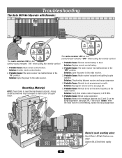
...OPEN RECEIVER GATE LOCKED CENTER LOOP The radio receiver LED on the CENTER LOOP control board remains "OFF" when using the remote control. 1. Solution: Cycle the power to the radio receiver. Probable Cause: Blown surge suppressor. EXIT LOOP STRIKE OPEN RADIO RECEIVER GATE LOCKED SAFETY LOOP CENTER LOOP RESET MOTOR CLOSE STOP OPEN POWER OVERLOAD MADE IN USA Motor(s) need resetting when: Reset Motor LED light flashes once, THEN System ON LED will flash rapidly 43 Solution: Cycle the power to the radio receiver. 3. Resetting Motor(s) NOTE: Press firmly to reach button...
...OPEN RECEIVER GATE LOCKED CENTER LOOP The radio receiver LED on the CENTER LOOP control board remains "OFF" when using the remote control. 1. Solution: Cycle the power to the radio receiver. Probable Cause: Blown surge suppressor. EXIT LOOP STRIKE OPEN RADIO RECEIVER GATE LOCKED SAFETY LOOP CENTER LOOP RESET MOTOR CLOSE STOP OPEN POWER OVERLOAD MADE IN USA Motor(s) need resetting when: Reset Motor LED light flashes once, THEN System ON LED will flash rapidly 43 Solution: Cycle the power to the radio receiver. 3. Resetting Motor(s) NOTE: Press firmly to reach button...
Owners Manual
Page 48
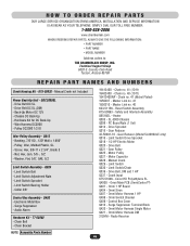
... - INSTALLATION AND SERVICE INFORMATION IS AS NEAR AS YOUR TELEPHONE. Drive Belt DC SL - Bushing, 7/8" OD, .120" Wall x 1.950" - Limit Switch Adjustment Nuts - Drive Belt Q021 - Manual Crank Q029 - Omni Siren Q407 - Control Box Cover Q410 - Omni Motor Harness DM 312HM - SIMPLY DIAL OUR TOLL FREE NUMBER: 1-800-528-2806 www.chamberlain.com WHEN ORDERING REPAIR PARTS, ALWAYS GIVE THE FOLLOWING INFORMATION: • PART NUMBER • PART NAME • MODEL NUMBER Address orders to: THE CHAMBERLAIN GROUP, INC. Technical Support...
... - INSTALLATION AND SERVICE INFORMATION IS AS NEAR AS YOUR TELEPHONE. Drive Belt DC SL - Bushing, 7/8" OD, .120" Wall x 1.950" - Limit Switch Adjustment Nuts - Drive Belt Q021 - Manual Crank Q029 - Omni Siren Q407 - Control Box Cover Q410 - Omni Motor Harness DM 312HM - SIMPLY DIAL OUR TOLL FREE NUMBER: 1-800-528-2806 www.chamberlain.com WHEN ORDERING REPAIR PARTS, ALWAYS GIVE THE FOLLOWING INFORMATION: • PART NUMBER • PART NAME • MODEL NUMBER Address orders to: THE CHAMBERLAIN GROUP, INC. Technical Support...
Owners Manual
Page 50
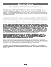
... COVER NON-DEFECT DAMAGE, DAMAGE CAUSED BY IMPROPER INSTALLATION, OPERATION OR CARE (INCLUDING, BUT NOT LIMITED TO ABUSE, MISUSE, FAILURE TO PROVIDE REASONABLE AND NECESSARY MAINTENANCE, UNAUTHORIZED REPAIRS OR ANY ALTERATIONS TO THIS PRODUCT), LABOR CHARGES FOR REINSTALLING A REPAIRED OR REPLACED UNIT, OR REPLACEMENT OF BATTERIES. Please include a brief description of the problem and a dated proof-of-purchase receipt with the instructions regarding installation, operation, maintenance...
... COVER NON-DEFECT DAMAGE, DAMAGE CAUSED BY IMPROPER INSTALLATION, OPERATION OR CARE (INCLUDING, BUT NOT LIMITED TO ABUSE, MISUSE, FAILURE TO PROVIDE REASONABLE AND NECESSARY MAINTENANCE, UNAUTHORIZED REPAIRS OR ANY ALTERATIONS TO THIS PRODUCT), LABOR CHARGES FOR REINSTALLING A REPAIRED OR REPLACED UNIT, OR REPLACEMENT OF BATTERIES. Please include a brief description of the problem and a dated proof-of-purchase receipt with the instructions regarding installation, operation, maintenance...


