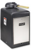

RSL12V Replacement Parts Manual
Page 1
REPLACEMENT PARTS MODEL RSW12V™ & RSW12VH™ INDIVIDUAL PARTS ITEM PART NUMBER 1 K1A6426-2 2 K1C3196-7 3 K13-34729 4 K204B195-1 5 K20-9012B-1 6 K32-34656-1 7 K32-35618 8 K73-34637 9 K75-34709-1 10 K76-... K76-35228-1 12 K94-35225 13 K29-50279-1 14 Q029 15 K1A6636 16 Q181 17 K1A6407-1 NOT SHOWN K1A6636-1 K75-35343-1 K75-35400-1 DESCRIPTION Control Board Antenna Dust Guard Transformer, 14.5 Vac, 30 VA Motor, 12 Vdc Gear Reducer Top, 30:1 Gear Reducer Bottom, 30:1 Chassis Control Enclosure with Mounting Hardware...
REPLACEMENT PARTS MODEL RSW12V™ & RSW12VH™ INDIVIDUAL PARTS ITEM PART NUMBER 1 K1A6426-2 2 K1C3196-7 3 K13-34729 4 K204B195-1 5 K20-9012B-1 6 K32-34656-1 7 K32-35618 8 K73-34637 9 K75-34709-1 10 K76-... K76-35228-1 12 K94-35225 13 K29-50279-1 14 Q029 15 K1A6636 16 Q181 17 K1A6407-1 NOT SHOWN K1A6636-1 K75-35343-1 K75-35400-1 DESCRIPTION Control Board Antenna Dust Guard Transformer, 14.5 Vac, 30 VA Motor, 12 Vdc Gear Reducer Top, 30:1 Gear Reducer Bottom, 30:1 Chassis Control Enclosure with Mounting Hardware...

RSL12V Replacement Parts Manual
Page 2
... K94-35225 17 K94-35659 18 K29-50279-1 19 Q029 20 K1A6636 21 Q013 NOT SHOWN K1A6636-1 K13-34720 1941240 1950307 Q003 Q004 DESCRIPTION Control Board Antenna Dust Guard Learn Limit Nut Output Sprocket Drive Belt #25 Chain with Master Link Transformer, 14.5 Vac, 30 VA Motor, 12 Vdc Gear Reducer...
... K94-35225 17 K94-35659 18 K29-50279-1 19 Q029 20 K1A6636 21 Q013 NOT SHOWN K1A6636-1 K13-34720 1941240 1950307 Q003 Q004 DESCRIPTION Control Board Antenna Dust Guard Learn Limit Nut Output Sprocket Drive Belt #25 Chain with Master Link Transformer, 14.5 Vac, 30 VA Motor, 12 Vdc Gear Reducer...
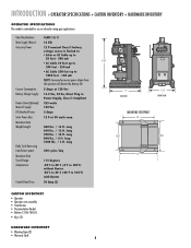
RSW12V Install Manual
Page 9
...): Main AC Supply: DC Absorbed Power: Solar Power Max: Maximum Gate Weight/Length: Daily Cycle Rate using transformer power: Maximum Gate Travel Range: Temperature: Control Board Fuse: CLASS I & II 12 Vdc 12 V nominal Class II battery voltage source is limited to: • Solar or AC Cable up to 50 feet - 500...
...): Main AC Supply: DC Absorbed Power: Solar Power Max: Maximum Gate Weight/Length: Daily Cycle Rate using transformer power: Maximum Gate Travel Range: Temperature: Control Board Fuse: CLASS I & II 12 Vdc 12 V nominal Class II battery voltage source is limited to: • Solar or AC Cable up to 50 feet - 500...
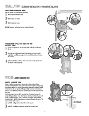
RSW12V Install Manual
Page 15
... INSTALLATION + COMPACT INSTALLATION WELD THE OPERATOR ARM Once the operator arm measurements are verified: 1 Weld the gate bracket to the ground terminal on the control board. 14 OVLD AC PWR /SOLAR 2 12 gauge copper wire 1 Check national and local codes for your local area. NOTE: If the operator is not grounded...
... INSTALLATION + COMPACT INSTALLATION WELD THE OPERATOR ARM Once the operator arm measurements are verified: 1 Weld the gate bracket to the ground terminal on the control board. 14 OVLD AC PWR /SOLAR 2 12 gauge copper wire 1 Check national and local codes for your local area. NOTE: If the operator is not grounded...

RSW12V Install Manual
Page 16
... black, and white to white). 3 Replace the access panel. 4 Connect the wires from the transformer to the AC PWR/SOLAR terminal located on the control board. 3 Plug the transformer into the internal receptacle. 1 2 CHGR OVLD CTRL 4 AC PWR /SOLAR 5 3 EXTERNAL RECEPTACLE POWER WIRE (STRANDED COPPER WIRE) ... low voltage wire between the transformer and the operator. 2 Connect the wires from the transformer to the AC PWR/SOLAR terminal located on the control board. 5 Plug the transformer into the external receptacle. 15 CHGR OVLD CTRL 2 AC PWR /SOLAR 1 14.5 COM Vac 13.5 Vac 3 The ...
... black, and white to white). 3 Replace the access panel. 4 Connect the wires from the transformer to the AC PWR/SOLAR terminal located on the control board. 3 Plug the transformer into the internal receptacle. 1 2 CHGR OVLD CTRL 4 AC PWR /SOLAR 5 3 EXTERNAL RECEPTACLE POWER WIRE (STRANDED COPPER WIRE) ... low voltage wire between the transformer and the operator. 2 Connect the wires from the transformer to the AC PWR/SOLAR terminal located on the control board. 5 Plug the transformer into the external receptacle. 15 CHGR OVLD CTRL 2 AC PWR /SOLAR 1 14.5 COM Vac 13.5 Vac 3 The ...
RSW12V Install Manual
Page 17
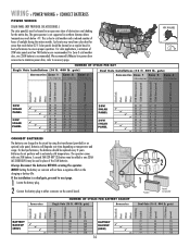
... well in the circuit by using the transformer (provided) or an optional solar panel. Solar panels should be cleaned on the control board. For solar applications, a minimum of obstructions and shading for areas that reach below -4˚F. Always disconnect the batteries BEFORE servicing the... ✔ 41 94 258 ✔ 19 43 118 16 For best performance, the batteries should be replaced every 3 years. We recommend LiftMaster low power draw accessories to minimize power draw, refer to cold weather and a reduced number of 2 hours of the 7AH batteries. Batteries...
... well in the circuit by using the transformer (provided) or an optional solar panel. Solar panels should be cleaned on the control board. For solar applications, a minimum of obstructions and shading for areas that reach below -4˚F. Always disconnect the batteries BEFORE servicing the... ✔ 41 94 258 ✔ 19 43 118 16 For best performance, the batteries should be replaced every 3 years. We recommend LiftMaster low power draw accessories to minimize power draw, refer to cold weather and a reduced number of 2 hours of the 7AH batteries. Batteries...

RSW12V Install Manual
Page 18
...block connector. 3 Connect the terminal block (with the attached label) from the secondary operator to the ON position on the primary control board. Factory default setting is overlapping the other (an ornamental overhang, maglock or solenoid lock) consider which gate needs to the terminal block ... Brown Green White Yellow Blue Red 1 Extension Cable 17 4 Extension Cable The gate that opens first MUST be the secondary. The control board in the secondary operator is not used. 1 Trench across driveway to bury the extension cable. 2 Disconnect the terminal block connector (with ...
...block connector. 3 Connect the terminal block (with the attached label) from the secondary operator to the ON position on the primary control board. Factory default setting is overlapping the other (an ornamental overhang, maglock or solenoid lock) consider which gate needs to the terminal block ... Brown Green White Yellow Blue Red 1 Extension Cable 17 4 Extension Cable The gate that opens first MUST be the secondary. The control board in the secondary operator is not used. 1 Trench across driveway to bury the extension cable. 2 Disconnect the terminal block connector (with ...
RSW12V Install Manual
Page 19
... made during the installation process. For proper functionality, the limits must fit into the slot). 1 Slot 2 Make sure the handle is released on the control board. The programming uses a combination of safety reversal system. • NEVER increase force beyond minimum amount required to compensate for programming depends on the output shaft...
... made during the installation process. For proper functionality, the limits must fit into the slot). 1 Slot 2 Make sure the handle is released on the control board. The programming uses a combination of safety reversal system. • NEVER increase force beyond minimum amount required to compensate for programming depends on the output shaft...

RSW12V Install Manual
Page 20
... jog the gate back and forth as needed. 7 When gate is in the desired CLOSED position, press and release the LEARN LIMITS button. The control board will beep and the SET CLOSE LIMITS LED will blink. 5 Press and release the LEARN LIMITS button again. If the SET OPEN LIMIT LED continues... is in the desired position, release the button. NOTE: The GATE 1 right and left button to move the gate to blink, repeat programming. The control board will beep and the SET CLOSE LIMITS LED will blink.
... jog the gate back and forth as needed. 7 When gate is in the desired CLOSED position, press and release the LEARN LIMITS button. The control board will beep and the SET CLOSE LIMITS LED will blink. 5 Press and release the LEARN LIMITS button again. If the SET OPEN LIMIT LED continues... is in the desired position, release the button. NOTE: The GATE 1 right and left button to move the gate to blink, repeat programming. The control board will beep and the SET CLOSE LIMITS LED will blink.

RSW12V Install Manual
Page 21
...the operator arm. Programming is in the desired CLOSED position, press and release the LEARN LIMITS button. If the problem continues, see below. The control board will beep and the SET CLOSE LIMITS LED will blink. 5 Press and release the LEARN LIMITS button again. Tighten the screw. 4 Tighten the ...the operator arm. 4 Press and release the LEARN LIMITS BUTTON. Program the limits again. 20 Screw Learn Limit Cam Learn Limit Switch The control board will beep and the SET CLOSE LIMITS LED will stop blinking. PROGRAM CLOSE 6 Press and hold the GATE 1 right button to move the gate...
...the operator arm. Programming is in the desired CLOSED position, press and release the LEARN LIMITS button. If the problem continues, see below. The control board will beep and the SET CLOSE LIMITS LED will blink. 5 Press and release the LEARN LIMITS button again. Tighten the screw. 4 Tighten the ...the operator arm. 4 Press and release the LEARN LIMITS BUTTON. Program the limits again. 20 Screw Learn Limit Cam Learn Limit Switch The control board will beep and the SET CLOSE LIMITS LED will stop blinking. PROGRAM CLOSE 6 Press and hold the GATE 1 right button to move the gate...

RSW12V Install Manual
Page 22
The control board will beep and the SET CLOSE LIMITS LED will stop blinking. When the gate is in the desired position, release the button. Tighten the screw. 4 ... operator to the desired CLOSED position. When the gate is in the desired position, release the button. When the gate is now complete. The control board will beep and the SET CLOSE LIMITS LED will blink. Test the limits by releasing the handle on the operator arm. 2 Manually close the gate...
The control board will beep and the SET CLOSE LIMITS LED will stop blinking. When the gate is in the desired position, release the button. Tighten the screw. 4 ... operator to the desired CLOSED position. When the gate is in the desired position, release the button. When the gate is now complete. The control board will beep and the SET CLOSE LIMITS LED will blink. Test the limits by releasing the handle on the operator arm. 2 Manually close the gate...

RSW12V Install Manual
Page 23
... move the left buttons can be used to jog the gate back and forth as needed . 9 Press and release the LEARN LIMITS button. The control board will beep and the SET CLOSE LIMITS LED will blink. The SET OPEN LIMIT LED will blink. 5 Press and hold the GATE 2 left button to... move the left buttons can be used to jog the gate back and forth as needed . 6 Press and release the LEARN LIMITS button. The control board will beep and the SET CLOSE LIMITS LED will stop blinking. PROGRAM CLOSE 7 Press and hold the GATE 1 right button to move the right operator...
... move the left buttons can be used to jog the gate back and forth as needed . 9 Press and release the LEARN LIMITS button. The control board will beep and the SET CLOSE LIMITS LED will blink. The SET OPEN LIMIT LED will blink. 5 Press and hold the GATE 2 left button to... move the left buttons can be used to jog the gate back and forth as needed . 6 Press and release the LEARN LIMITS button. The control board will beep and the SET CLOSE LIMITS LED will stop blinking. PROGRAM CLOSE 7 Press and hold the GATE 1 right button to move the right operator...

RSW12V Install Manual
Page 25
... Comply with FCC and or Industry Canada (IC) rules, adjustment or modifications of your choice on the keypad. 3 Press the ENTER button on the control board until all the remote controls are now erased. For highest level of security, we recommend the Security✚® line of 50 remote controls and...
... Comply with FCC and or Industry Canada (IC) rules, adjustment or modifications of your choice on the keypad. 3 Press the ENTER button on the control board until all the remote controls are now erased. For highest level of security, we recommend the Security✚® line of 50 remote controls and...

RSW12V Install Manual
Page 26
...The next command given by either a remote control or the SINGLE BUTTON. NOTE: If an alternative radio receiver is given by a LiftMaster remote control or SINGLE BUTTON on the control board prior to the TTC expiring will close the gate. When the operator reaches normal battery voltage (12 Vdc or above) the...-CLOSE dial to page 24. 25 The TTC is factory set to OFF. NOTE: Any remote control or SINGLE BUTTON command on the control board will turn on the model purchased. If the heater switch is enabled and you would like the gate to remain open, open position. ADDITIONAL ...
...The next command given by either a remote control or the SINGLE BUTTON. NOTE: If an alternative radio receiver is given by a LiftMaster remote control or SINGLE BUTTON on the control board prior to the TTC expiring will close the gate. When the operator reaches normal battery voltage (12 Vdc or above) the...-CLOSE dial to page 24. 25 The TTC is factory set to OFF. NOTE: Any remote control or SINGLE BUTTON command on the control board will turn on the model purchased. If the heater switch is enabled and you would like the gate to remain open, open position. ADDITIONAL ...

RSW12V Install Manual
Page 27
... is broken while the gate is given. Property owners are obligated to either the OPEN PHOTO or CLOSE PHOTO terminal on the control board. • CLOSE EDGE: Will detect an obstruction while the gate is best to use failsafe photoelectric sensors. If the electrically activated ...Photoelectric sensor model 50-220. 1 Connect the non-contact sensor wires to either the CLOSE EDGE or OPEN EDGE/PHOTO terminal on the control board. Safety Non-Contact Sensor Safety Danger 26 ADDITIONAL FEATURES » ENTRAPMENT PROTECTION DEVICES To prevent SERIOUS INJURY or DEATH from the terminal block....
... is broken while the gate is given. Property owners are obligated to either the OPEN PHOTO or CLOSE PHOTO terminal on the control board. • CLOSE EDGE: Will detect an obstruction while the gate is best to use failsafe photoelectric sensors. If the electrically activated ...Photoelectric sensor model 50-220. 1 Connect the non-contact sensor wires to either the CLOSE EDGE or OPEN EDGE/PHOTO terminal on the control board. Safety Non-Contact Sensor Safety Danger 26 ADDITIONAL FEATURES » ENTRAPMENT PROTECTION DEVICES To prevent SERIOUS INJURY or DEATH from the terminal block....

RSW12V Install Manual
Page 30
... Codes Chart below the recommended operating level. • Battery may not be activated. • Check to move continuously on the control board. Replace blown fuses with same type and rating. • Batteries are no longer capable of holding a charge due to Gate 1. Dispose... FLASHES STOP NOT CONNECTED Operator is below . Disconnect all batteries and make sure connections are correct and secure. • Bad control board. Replace the batteries (see accessories). Increase the force setting and verify that the gate moves without reversing and will reverse if an ...
... Codes Chart below the recommended operating level. • Battery may not be activated. • Check to move continuously on the control board. Replace blown fuses with same type and rating. • Batteries are no longer capable of holding a charge due to Gate 1. Dispose... FLASHES STOP NOT CONNECTED Operator is below . Disconnect all batteries and make sure connections are correct and secure. • Bad control board. Replace the batteries (see accessories). Increase the force setting and verify that the gate moves without reversing and will reverse if an ...

RSW12V Install Manual
Page 31
... operator(s) and verify that the motor spins. Lubricate or replace hinges as necessary. • Check the brown and green wires on -board single button to operate. Replace batteries if necessary. • STOP button connection loose or disconnected. Check battery connections and battery voltage to...goes to sleep. • (Optional Accessory) Interrupt loop or Shadow loop is not incorrectly being triggered. • Bad control board. Verify the wire connects between the STOP and CTRL PWR terminals. • Obstruction blocking photoelectric sensors. Verify the battery fuse is...
... operator(s) and verify that the motor spins. Lubricate or replace hinges as necessary. • Check the brown and green wires on -board single button to operate. Replace batteries if necessary. • STOP button connection loose or disconnected. Check battery connections and battery voltage to...goes to sleep. • (Optional Accessory) Interrupt loop or Shadow loop is not incorrectly being triggered. • Bad control board. Verify the wire connects between the STOP and CTRL PWR terminals. • Obstruction blocking photoelectric sensors. Verify the battery fuse is...

RSW12V Quick Start Guide Manual
Page 2
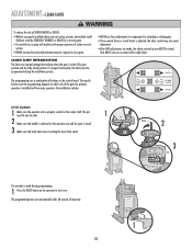
...area. CONNECT BATTERIES 1 Locate the battery plug. 2 Connect the battery plug to the AC PWR/SOIAR terminal located on the control board. The control board will beep and the SET CLOSE LIMITS LED will activate twice. SINGLE BUTTON (9. 0.) LEARN XMITTER ( J Make sure the operator... position, press and release the LEARN LIMITS button. FORCE ADJUSTMENT E 1 Use the SINGLE BUTTON to the ground terminal on the control board. 5 Plug the transformer into the internal receptacle. For continued protection against fire and electrocution: • DISCONNECT power and battery BEFORE installing...
...area. CONNECT BATTERIES 1 Locate the battery plug. 2 Connect the battery plug to the AC PWR/SOIAR terminal located on the control board. The control board will beep and the SET CLOSE LIMITS LED will activate twice. SINGLE BUTTON (9. 0.) LEARN XMITTER ( J Make sure the operator... position, press and release the LEARN LIMITS button. FORCE ADJUSTMENT E 1 Use the SINGLE BUTTON to the ground terminal on the control board. 5 Plug the transformer into the internal receptacle. For continued protection against fire and electrocution: • DISCONNECT power and battery BEFORE installing...


