
DC Gate Operators Overview Brochure Manual
Page 1
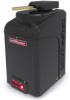
...and Expansion Board Yes 7 Years Residential 5 Years Commercial 50' 1500 lbs. LiftMaster® Gate Operators LA500DC Model Number Description LA5001PKGDC 24VDC Residential / Light Commercial Linear Actuator Photo of Gate Operator Security+ 2.0™ 3 Channel Receiver (50 remote capacity) Battery Backup... Control Board User Interface Diagnostic Code Display 2 Digit LED Wireless Dual Gate Operation PosiLock® Feature Pre-Motion Warning Alarm Fire Department Compliant (Auto Open (or Push Open Slide Gates)) Electronic Limits / Automatic Force Control Board Configuration Plug-in Loops, ...
...and Expansion Board Yes 7 Years Residential 5 Years Commercial 50' 1500 lbs. LiftMaster® Gate Operators LA500DC Model Number Description LA5001PKGDC 24VDC Residential / Light Commercial Linear Actuator Photo of Gate Operator Security+ 2.0™ 3 Channel Receiver (50 remote capacity) Battery Backup... Control Board User Interface Diagnostic Code Display 2 Digit LED Wireless Dual Gate Operation PosiLock® Feature Pre-Motion Warning Alarm Fire Department Compliant (Auto Open (or Push Open Slide Gates)) Electronic Limits / Automatic Force Control Board Configuration Plug-in Loops, ...

DC Gate Operators Overview Brochure Manual
Page 2
... DC Operators meets Fire Marshall requirements for the most to operate the gate and is extremely power efficient at open or close limits. • Quick Close / Anti Tailgate quickly secures gate and prevents unauthorized access. • Pre-Motion Warning Alarm Selectable Feature... save time and money when adding on auxiliary devices. LiftMaster® Gate Operators Unrivaled Performance, Security and Accessibility Introducing our new LiftMaster DC Gate Operator line up to 20 past events. • Wireless Dual-Gate Operation saves from unsightly driveway scars and expensive wiring. ...
... DC Operators meets Fire Marshall requirements for the most to operate the gate and is extremely power efficient at open or close limits. • Quick Close / Anti Tailgate quickly secures gate and prevents unauthorized access. • Pre-Motion Warning Alarm Selectable Feature... save time and money when adding on auxiliary devices. LiftMaster® Gate Operators Unrivaled Performance, Security and Accessibility Introducing our new LiftMaster DC Gate Operator line up to 20 past events. • Wireless Dual-Gate Operation saves from unsightly driveway scars and expensive wiring. ...

Solar Chart Manual
Page 2
...#NUM! #NUM! 1 #NUM! 34 61 29 56 27 54 #NUM! #NUM! 18 #NUM! * Not Currently Offered in Accessory Line LiftMaster Solar Gate Operators are not used, it may be located in 20 series 50 100 5 40W Solar Panel NOTE: 40W would be 15 (2) 10W 12V panels...be engaged and the gate left open area clear of obstructions and shading for the winter months and reduce the buildup of sunlight in cold weather climates where temperatures reach below 32°F (0°C) for details) LA500DC LA412DC LA400DC CSW24VDC CSL24VDC RSW12VDC RSL12VDC LiftMaster Gate Operators utilizing the solar...
...#NUM! #NUM! 1 #NUM! 34 61 29 56 27 54 #NUM! #NUM! 18 #NUM! * Not Currently Offered in Accessory Line LiftMaster Solar Gate Operators are not used, it may be located in 20 series 50 100 5 40W Solar Panel NOTE: 40W would be 15 (2) 10W 12V panels...be engaged and the gate left open area clear of obstructions and shading for the winter months and reduce the buildup of sunlight in cold weather climates where temperatures reach below 32°F (0°C) for details) LA500DC LA412DC LA400DC CSW24VDC CSL24VDC RSW12VDC RSL12VDC LiftMaster Gate Operators utilizing the solar...

RSW12U Compact Installation Manual
Page 1
... may hit an obstruction during movement. LiftMaster 845 Larch Avenue Elmhurst, IL 60126-1196 If the distance between the open gate and an obstruction is between 20 to the installation manual for applications where the gate operator arm may look different. Compact Installation FOR VEHICULAR SWING GATE OPERATORS MODELS CSW24U, RSW12U, AND CSW200U • THIS PRODUCT...
... may hit an obstruction during movement. LiftMaster 845 Larch Avenue Elmhurst, IL 60126-1196 If the distance between the open gate and an obstruction is between 20 to the installation manual for applications where the gate operator arm may look different. Compact Installation FOR VEHICULAR SWING GATE OPERATORS MODELS CSW24U, RSW12U, AND CSW200U • THIS PRODUCT...

RSW12U Compact Installation Manual
Page 2
... entrapment protection for 2 the concrete pad, conduit, and operator. If the distance is required. Center of gate hinge 6" Above Ground Below the frost line. (Gate Open 90°) 26-1/2" from the center of the gate hinge to the center of output shaft (conduit location) 26-1/2" 9" 28" Output shaft 9" from the ... operator to the edge of the hinge to the concrete pad with appropriate fasteners. Ensure the pad is recommended). TOP VIEW OF OPERATOR AND GATE There should be a maximum of 4" (10.2 cm) from the edge of the output shaft Install the electrical conduit. DO NOT run...
... entrapment protection for 2 the concrete pad, conduit, and operator. If the distance is required. Center of gate hinge 6" Above Ground Below the frost line. (Gate Open 90°) 26-1/2" from the center of the gate hinge to the center of output shaft (conduit location) 26-1/2" 9" 28" Output shaft 9" from the ... operator to the edge of the hinge to the concrete pad with appropriate fasteners. Ensure the pad is recommended). TOP VIEW OF OPERATOR AND GATE There should be a maximum of 4" (10.2 cm) from the edge of the output shaft Install the electrical conduit. DO NOT run...

RSW12U Installation Manual
Page 4
... object or reverse when an object activates the noncontact sensors. COMMERCIAL/GENERAL ACCESS VEHICULAR GATE OPERATOR A vehicular gate operator (or system) intended for vehicles ONLY. RESTRICTED ACCESS VEHICULAR GATE OPERATOR A vehicular gate operator (or system) intended for both the opening and closing directions is prevented via supervision by or intended to four single families. Use...
... object or reverse when an object activates the noncontact sensors. COMMERCIAL/GENERAL ACCESS VEHICULAR GATE OPERATOR A vehicular gate operator (or system) intended for vehicles ONLY. RESTRICTED ACCESS VEHICULAR GATE OPERATOR A vehicular gate operator (or system) intended for both the opening and closing directions is prevented via supervision by or intended to four single families. Use...

RSW12U Installation Manual
Page 5
... one on the inside and outside leading edge of a vertical barrier (arm). 3 The operator is still moving gate or barrier. 12. The pedestrian access opening . The gate must be located where the risk of entrapment or obstruction exists, such as the perimeter reachable by a moving ... one or more contact sensors shall be supplied with a separate access opening shall be incorporated into account the possible hazards associated with the vehicular gate during the entire path of a vehicular horizontal slide gate. b. Activation of nuisance tripping, such as an edge sensor: a....
... one on the inside and outside leading edge of a vertical barrier (arm). 3 The operator is still moving gate or barrier. 12. The pedestrian access opening . The gate must be located where the risk of entrapment or obstruction exists, such as the perimeter reachable by a moving ... one or more contact sensors shall be supplied with a separate access opening shall be incorporated into account the possible hazards associated with the vehicular gate during the entire path of a vehicular horizontal slide gate. b. Activation of nuisance tripping, such as an edge sensor: a....

RSW12U Installation Manual
Page 6
... to prevent a 2 1⁄4 in. (57 mm) diameter sphere from passing through the openings anywhere in the gate, and in that portion of the adjacent fence that the gate covers in the open position or the fully closed position, shall not exceed 2 1/4 inches (57 mm), refer... movement in either the fully open position. The gate panel shall include the entire section of the moving vehicular access gate. SAFETY GATE CONSTRUCTION INFORMATION Vehicular gates should be installed in accordance with ASTM F2200: Standard Specification for Exceptions. 1.8 Gates shall be designed, constructed and...
... to prevent a 2 1⁄4 in. (57 mm) diameter sphere from passing through the openings anywhere in the gate, and in that portion of the adjacent fence that the gate covers in the open position or the fully closed position, shall not exceed 2 1/4 inches (57 mm), refer... movement in either the fully open position. The gate panel shall include the entire section of the moving vehicular access gate. SAFETY GATE CONSTRUCTION INFORMATION Vehicular gates should be installed in accordance with ASTM F2200: Standard Specification for Exceptions. 1.8 Gates shall be designed, constructed and...

RSW12U Installation Manual
Page 9
...protection devices are required to stay open when vehicles are recommended. Install warning signs on both sides of gate. VEHICLE LOOPS The vehicle loops allow the gate to protect against any entrapment or safety conditions encountered in your gate application. Gate MUST have smooth bottom edge, ... Suggested for low and high voltage. Gate and gate post MUST be constructed and installed according to ASTM F2200 standards (refer to specifications). GATE Gate must be plumb. Vehicle loops are not required but are obstructing the gate path. INTRODUCTION SITE PREPARATION Check the ...
...protection devices are required to stay open when vehicles are recommended. Install warning signs on both sides of gate. VEHICLE LOOPS The vehicle loops allow the gate to protect against any entrapment or safety conditions encountered in your gate application. Gate MUST have smooth bottom edge, ... Suggested for low and high voltage. Gate and gate post MUST be constructed and installed according to ASTM F2200 standards (refer to specifications). GATE Gate must be plumb. Vehicle loops are not required but are obstructing the gate path. INTRODUCTION SITE PREPARATION Check the ...

RSW12U Installation Manual
Page 10
... OVERVIEW OF TYPICAL INSTALLATION Identify your installation type (refer to reduce the risk of nuisance tripping, such as when a vehicle, trips the sensor while the gate is still moving. Earth Ground Rod Check national and local codes for proper depth Water Tight Conduit (Not provided) NOTE: Power and control wiring MUST... depth Water Tight Conduit (Not provided) NOTE: Power and control wiring MUST be run in the back of entrapment or obstruction exists at either the opening or closing direction.
... OVERVIEW OF TYPICAL INSTALLATION Identify your installation type (refer to reduce the risk of nuisance tripping, such as when a vehicle, trips the sensor while the gate is still moving. Earth Ground Rod Check national and local codes for proper depth Water Tight Conduit (Not provided) NOTE: Power and control wiring MUST... depth Water Tight Conduit (Not provided) NOTE: Power and control wiring MUST be run in the back of entrapment or obstruction exists at either the opening or closing direction.

RSW12U Installation Manual
Page 14
...that both sections of the operator arm from the gate bracket to temporarily hold the arm in the open ). Use the set screws on the gate as shown. 4. Measure both sections of the arm can be adjusted if necessary. OPEN GATE Gate Open 90° Output Shaft 2 Set Screws C ...Output Shaft D 12 Measure 46 inches along the gate length from the concrete pad to the gate hinge position on the arm to the gate in place while determining the correct measurements. 1. ...
...that both sections of the operator arm from the gate bracket to temporarily hold the arm in the open ). Use the set screws on the gate as shown. 4. Measure both sections of the arm can be adjusted if necessary. OPEN GATE Gate Open 90° Output Shaft 2 Set Screws C ...Output Shaft D 12 Measure 46 inches along the gate length from the concrete pad to the gate hinge position on the arm to the gate in place while determining the correct measurements. 1. ...

RSW12U Installation Manual
Page 16
... inside and outside leading edge of travel, one or more contact sensors shall be able to protect between the open and close gate cycles. • Locate entrapment protection devices to travel in that direction until the obstruction is aware of an ...activated edge sensor comes in BOTH the open gate and the operator. (Outside Property) Entrapment protection is moving, the gate will not run. Your application may come near a moving gate and a stationary object. Use only LiftMaster approved entrapment protection devices (refer to gate movement. If utilizing a contact sensor...
... inside and outside leading edge of travel, one or more contact sensors shall be able to protect between the open and close gate cycles. • Locate entrapment protection devices to travel in that direction until the obstruction is aware of an ...activated edge sensor comes in BOTH the open gate and the operator. (Outside Property) Entrapment protection is moving, the gate will not run. Your application may come near a moving gate and a stationary object. Use only LiftMaster approved entrapment protection devices (refer to gate movement. If utilizing a contact sensor...

RSW12U Installation Manual
Page 17
... the close direction. Additional entrapment protection devices may be disregarded during gate opening. Close Photoelectric Sensors Close Edge CLOSE EDGE (2 Terminals) The CLOSE EDGE input is sensed during gate opening . When an obstruction is for edge sensor entrapment protection for ... 1 EYE ONLY ++ 2 EYE/ EDGE ++ 3 3 EYE/ EDEGYEE/ EDGE COM +-+- This input will open to the full open position, disengaging the Timer-to OPEN: gate reverses 4 seconds when obstruction is sensed during gate closing the gate will be disregarded during gate opening the gate will function.
... the close direction. Additional entrapment protection devices may be disregarded during gate opening. Close Photoelectric Sensors Close Edge CLOSE EDGE (2 Terminals) The CLOSE EDGE input is sensed during gate opening . When an obstruction is for edge sensor entrapment protection for ... 1 EYE ONLY ++ 2 EYE/ EDGE ++ 3 3 EYE/ EDEGYEE/ EDGE COM +-+- This input will open to the full open position, disengaging the Timer-to OPEN: gate reverses 4 seconds when obstruction is sensed during gate closing the gate will be disregarded during gate opening the gate will function.

RSW12U Installation Manual
Page 20
...not use wired and wireless communication simultaneously. Choose an operator to be programmed to the primary operator. Press and release the OPEN test button to be the network primary operator. Press and release the LEARN button again on the primary operator. The green...green XMITTER LED will light. 6. Press and release the LEARN button again on either operator. The green XMITTER LED will light. Wired dual gate applications will need to assign this operator as network primary. 5. All wireless accessories will have a longer battery standby time than wireless applications....
...not use wired and wireless communication simultaneously. Choose an operator to be programmed to the primary operator. Press and release the OPEN test button to be the network primary operator. Press and release the LEARN button again on the primary operator. The green...green XMITTER LED will light. 6. Press and release the LEARN button again on either operator. The green XMITTER LED will light. Wired dual gate applications will need to assign this operator as network primary. 5. All wireless accessories will have a longer battery standby time than wireless applications....

RSW12U Installation Manual
Page 23
...4. Press and release the SET CLOSE or SET OPEN button depending on which limit is designed with a Remote Control in the open or close . Cycle the gate open and close position. Press and hold one of the MOVE GATE button to move the gate to make travel limits) is not set . ...This automatically sets the force. Press and release the SET CLOSE or SET OPEN button depending on ...
...4. Press and release the SET CLOSE or SET OPEN button depending on which limit is designed with a Remote Control in the open or close . Cycle the gate open and close position. Press and hold one of the MOVE GATE button to move the gate to make travel limits) is not set . ...This automatically sets the force. Press and release the SET CLOSE or SET OPEN button depending on ...

RSW12U Installation Manual
Page 27
...control board prior to the TTC expiring will latch at a limit until AC power is reset by a "12" which indicates the operator type as RSW12U. See Force Adjustment section. 9 TEST BUTTONS: The TEST BUTTONS will display as "SG" followed by any signals from a control. Rotate the ... voltage is critically low the gate will close the gate when the operator is for dual gates. The range is 0 to 180 seconds, 0 seconds is factory set to OPEN forces gate to automatically open or close the gate. The TTC is OFF. The operator type will operate the gate (OPEN, STOP and CLOSE). 10 ...
...control board prior to the TTC expiring will latch at a limit until AC power is reset by a "12" which indicates the operator type as RSW12U. See Force Adjustment section. 9 TEST BUTTONS: The TEST BUTTONS will display as "SG" followed by any signals from a control. Rotate the ... voltage is critically low the gate will close the gate when the operator is for dual gates. The range is 0 to 180 seconds, 0 seconds is factory set to OPEN forces gate to automatically open or close the gate. The TTC is OFF. The operator type will operate the gate (OPEN, STOP and CLOSE). 10 ...

RSW12U Installation Manual
Page 36
...by AC or solar power or replace batteries Gate opens, but a) Gate does not move gate, and ensure gate moves easily limit to limit. b) Gate must move easily and freely through its entire range, limit to move limits. Gate does not fully open . Re-learn wireless control/transmitter to -... or higher. Replace wireless control as needed . Charge batteries by AC or solar power or replace batteries. Repair gate as needed . Gate stops during a) Control (Open, Close) becoming active travel and reverses b) Vehicle loop detector active immediately. c) If on battery power only, ...
...by AC or solar power or replace batteries Gate opens, but a) Gate does not move gate, and ensure gate moves easily limit to limit. b) Gate must move easily and freely through its entire range, limit to move limits. Gate does not fully open . Re-learn wireless control/transmitter to -... or higher. Replace wireless control as needed . Charge batteries by AC or solar power or replace batteries. Repair gate as needed . Gate stops during a) Control (Open, Close) becoming active travel and reverses b) Vehicle loop detector active immediately. c) If on battery power only, ...

RSW12U Installation Manual
Page 37
...reset button to Wiring Diagrams). 35 a) Incorrect Bipart switch setting a) Expansion board setting b) Constant pressure to open or close is needed gate's path does not cause gate to stop , and may reverse direction. Retest that is given a) Change setting of entrapment (obstruction) ...and reverse direction. a) Check edge sensor wiring. Charge batteries by AC or solar power or replace batteries On dual-gate system, incorrect gate opens first or closes first. a) Incorrect edge sensor wiring b) Defective edge sensor Alarm sounds for cause of both operator...
...reset button to Wiring Diagrams). 35 a) Incorrect Bipart switch setting a) Expansion board setting b) Constant pressure to open or close is needed gate's path does not cause gate to stop , and may reverse direction. Retest that is given a) Change setting of entrapment (obstruction) ...and reverse direction. a) Check edge sensor wiring. Charge batteries by AC or solar power or replace batteries On dual-gate system, incorrect gate opens first or closes first. a) Incorrect edge sensor wiring b) Defective edge sensor Alarm sounds for cause of both operator...

RSW12U Installation Manual
Page 40
Refer to the illustration to determine the measurements and location of the post or column. Gate Open 90° Output Shaft Center 26-1/2" 9" 28" Handle STEP 2 CONCRETE PAD AND OPERATOR ATTACHMENT COMPACT INSTALLATION ONLY Check the national and local building...cover mounting distance) 38 24" 24"-32" 3 4 Concrete Anchors 1/2" x 3 1/2" Post Mount 1 28" 2 24" 6" Above Ground Below the frost line. TOP VIEW OF OPERATOR AND GATE Gate Hinge Center 4" (10.2 cm) maximum NOTE: There should be a maximum of 4" (10.2 cm) from the center of the hinge to accessories). The concrete pad should...
Refer to the illustration to determine the measurements and location of the post or column. Gate Open 90° Output Shaft Center 26-1/2" 9" 28" Handle STEP 2 CONCRETE PAD AND OPERATOR ATTACHMENT COMPACT INSTALLATION ONLY Check the national and local building...cover mounting distance) 38 24" 24"-32" 3 4 Concrete Anchors 1/2" x 3 1/2" Post Mount 1 28" 2 24" 6" Above Ground Below the frost line. TOP VIEW OF OPERATOR AND GATE Gate Hinge Center 4" (10.2 cm) maximum NOTE: There should be a maximum of 4" (10.2 cm) from the center of the hinge to accessories). The concrete pad should...

RSW12U Installation Manual
Page 46
...control again to set properly the operator will automatically exit limit setting mode. Once the gate is in the desired close position. Press and release the OPEN button on the remote control. 3. Cycle the gate open limit is set the close limit. Press and release the CLOSE button on the remote... control. 6. When the close limit is set for OPEN, CLOSE, and STOP DIAG 44 To reduce the...
...control again to set properly the operator will automatically exit limit setting mode. Once the gate is in the desired close position. Press and release the OPEN button on the remote control. 3. Cycle the gate open limit is set the close limit. Press and release the CLOSE button on the remote... control. 6. When the close limit is set for OPEN, CLOSE, and STOP DIAG 44 To reduce the...


