RSL12V Installation Manual
Page 2
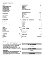
...25 25 25 26-29 26 27-28 29 30 BACK COVER TABLE OF CONTENTS SAFETY Safety Symbol and Signal Word Review UL325 Model Classifications Safety Installation Information Gate Construction Information Required Safety Protection Devices Important Safety Information INTRODUCTION Operator Specifications Carton ...Battery Drive Chain TROUBLESHOOTING Diagnostic Error Codes Chart Troubleshooting Chart Wiring Diagram ACCESSORIES WARRANTY SAFETY » SAFETY SYMBOL AND SIGNAL WORD REVIEW When you see this manual and follow all safety instructions. • DO NOT attempt repair or service of your gate ...
...25 25 25 26-29 26 27-28 29 30 BACK COVER TABLE OF CONTENTS SAFETY Safety Symbol and Signal Word Review UL325 Model Classifications Safety Installation Information Gate Construction Information Required Safety Protection Devices Important Safety Information INTRODUCTION Operator Specifications Carton ...Battery Drive Chain TROUBLESHOOTING Diagnostic Error Codes Chart Troubleshooting Chart Wiring Diagram ACCESSORIES WARRANTY SAFETY » SAFETY SYMBOL AND SIGNAL WORD REVIEW When you see this manual and follow all safety instructions. • DO NOT attempt repair or service of your gate ...

RSL12V Installation Manual
Page 13
...should be on the control board. 5 Plug the transformer into the external receptacle. WIRING » POWER WIRING POWER WIRING This operator can be reviewed for suitability of wire installation. 1 Remove the access panel. 2 Connect AC power to the operator: • Connect the green wire to ... guidelines. If wiring the heater to the internal receptacle, remove the knockout in a dry location that is protected from the transformer to be reviewed for suitability of the operator with wire nuts. The transformer must be wired. CHGR OVLD CTRL 2 AC PWR /SOLAR 1 14.5 Vac COM...
...should be on the control board. 5 Plug the transformer into the external receptacle. WIRING » POWER WIRING POWER WIRING This operator can be reviewed for suitability of wire installation. 1 Remove the access panel. 2 Connect AC power to the operator: • Connect the green wire to ... guidelines. If wiring the heater to the internal receptacle, remove the knockout in a dry location that is protected from the transformer to be reviewed for suitability of the operator with wire nuts. The transformer must be wired. CHGR OVLD CTRL 2 AC PWR /SOLAR 1 14.5 Vac COM...
RSL12V Wiring Diagram Manual
Page 1
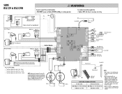
...13.5V output terminals. Allconnections are made locally to the terminalblock. The second(optional)batterymustbe usedinprimary/ secondary applicationsandmay be reviewed for suitability of same type and rating. • Maglock Power Supply C0M YMile NC Mad( NO Red Relay ... NO-1 - NO-4 NC-3 00M-2 - CTRL PWR s Open (Exit Loop) e•m•g-__, Single Button (SBC) g•m•g- SLIDE RSL12V & RSL12VH ®WARNING To protect against fire: • Replace ONLY with fuse of wire installation. For continued protection against fire and electrocution: •...
...13.5V output terminals. Allconnections are made locally to the terminalblock. The second(optional)batterymustbe usedinprimary/ secondary applicationsandmay be reviewed for suitability of same type and rating. • Maglock Power Supply C0M YMile NC Mad( NO Red Relay ... NO-1 - NO-4 NC-3 00M-2 - CTRL PWR s Open (Exit Loop) e•m•g-__, Single Button (SBC) g•m•g- SLIDE RSL12V & RSL12VH ®WARNING To protect against fire: • Replace ONLY with fuse of wire installation. For continued protection against fire and electrocution: •...

RSL12V Wiring Diagram Manual
Page 2
SWING RSW12V & RSW12VH &WARNING To protect against fire: • Replace ONLY with fuse of same type and rating. For continued protection against fire and electrocution: • DISCONNECT power and battery BEFORE installing or servicing operator. NOTE: Do notuse amaglodc anda solenoidlock on the same installation. • Magi ck Power Supply COM White NC Block NO Red R lay Adapter Mod le Marra Re --r-- Brown R J17 Green • we. • OR Yellow • lug • • • Brown rein mite :00 000 J16 ow B us 0 aa Block Red Black aN CMD ...
SWING RSW12V & RSW12VH &WARNING To protect against fire: • Replace ONLY with fuse of same type and rating. For continued protection against fire and electrocution: • DISCONNECT power and battery BEFORE installing or servicing operator. NOTE: Do notuse amaglodc anda solenoidlock on the same installation. • Magi ck Power Supply COM White NC Block NO Red R lay Adapter Mod le Marra Re --r-- Brown R J17 Green • we. • OR Yellow • lug • • • Brown rein mite :00 000 J16 ow B us 0 aa Block Red Black aN CMD ...