
RSL12V Installation Manual
Page 9
...CLASS I & II SIDE VIEW REAR VIEW Main Supply (Motor): 12 Vdc Accessory Power: 12 V nominal Class II battery voltage source is limited to: • Solar or AC Cable up to 50 feet - 500 mA • AC Cable 50 feet up to 250 feet - 250 mA 20-3/8" 20-3/8" Current Consumption: •... Vac, 30 Va, Direct Plug in Power Supply, Class II Compliant Heater Draw (Optional): 325 watts Main AC Supply: 120 Vac DC Absorbed Power: 2 Amps Solar Power Max: Maximum Gate Speed: 12 V at 30 watts max. 1 foot/second 24" 20-1/2" Maximum Gate Weight: 800 lb. 7-1/4" Daily Cycle Rate using transformer...
...CLASS I & II SIDE VIEW REAR VIEW Main Supply (Motor): 12 Vdc Accessory Power: 12 V nominal Class II battery voltage source is limited to: • Solar or AC Cable up to 50 feet - 500 mA • AC Cable 50 feet up to 250 feet - 250 mA 20-3/8" 20-3/8" Current Consumption: •... Vac, 30 Va, Direct Plug in Power Supply, Class II Compliant Heater Draw (Optional): 325 watts Main AC Supply: 120 Vac DC Absorbed Power: 2 Amps Solar Power Max: Maximum Gate Speed: 12 V at 30 watts max. 1 foot/second 24" 20-1/2" Maximum Gate Weight: 800 lb. 7-1/4" Daily Cycle Rate using transformer...

RSL12V Installation Manual
Page 12
.... 3 NOTE: The chain should not be level with the idler pulley and parallel to the ground terminal on the control board. 11 2 4 5 3 2 OVLD AC PWR /SOLAR 2 12 gauge copper wire 1 Check national and local codes for proper depth Weld the front bracket in this position. 3 Align the top bracket so the...
.... 3 NOTE: The chain should not be level with the idler pulley and parallel to the ground terminal on the control board. 11 2 4 5 3 2 OVLD AC PWR /SOLAR 2 12 gauge copper wire 1 Check national and local codes for proper depth Weld the front bracket in this position. 3 Align the top bracket so the...

RSL12V Installation Manual
Page 13
...wires through the knockout and connect the heater wires to the power wires of the operator with a heater it will have to the AC PWR/SOLAR terminal located on the control board. 5 Plug the transformer into the external receptacle. Run low voltage wire between the transformer and the operator.... 16 - 100 feet (30 m) Wire Gauge 10 - 1000 feet (305 m) NOTE: All power wiring should be wired. CHGR OVLD CTRL 2 AC PWR /SOLAR 1 14.5 Vac COM 13.5 Vac 3 12 The heater may be reviewed for suitability of wire installation. National and local electrical codes must be wired to...
...wires through the knockout and connect the heater wires to the power wires of the operator with a heater it will have to the AC PWR/SOLAR terminal located on the control board. 5 Plug the transformer into the external receptacle. Run low voltage wire between the transformer and the operator.... 16 - 100 feet (30 m) Wire Gauge 10 - 1000 feet (305 m) NOTE: All power wiring should be wired. CHGR OVLD CTRL 2 AC PWR /SOLAR 1 14.5 Vac COM 13.5 Vac 3 12 The heater may be reviewed for suitability of wire installation. National and local electrical codes must be wired to...

RSL12V Installation Manual
Page 14
... accessory page. NOTE: There may vary from solar chart for the 33AH battery if a heater is a dual gate, proceed to ensure proper operation. NOTE: Setting the battery on concrete will degrade over time depending on a regular basis for the entire day. We recommend LiftMaster low power draw accessories to minimize power draw...
... accessory page. NOTE: There may vary from solar chart for the 33AH battery if a heater is a dual gate, proceed to ensure proper operation. NOTE: Setting the battery on concrete will degrade over time depending on a regular basis for the entire day. We recommend LiftMaster low power draw accessories to minimize power draw...

RSL12V Installation Manual
Page 27
...• Check to make sure the jumper wire is connected between the COM and STOP input on the motor to make sure AC power or solar power is encountered. Verify AC power outlet. • Verify that the gate moves without reversing and will reverse if an obstruction is connected....moves freely. • If there is clear and the gate moves freely. • Incorrect or bad connection to make sure AC power or solar power is encountered. Disconnect all batteries and make sure connections are intact and not blown. The diagnostic LED will reverse if an obstruction is connected...
...• Check to make sure the jumper wire is connected between the COM and STOP input on the motor to make sure AC power or solar power is encountered. Verify AC power outlet. • Verify that the gate moves without reversing and will reverse if an obstruction is connected....moves freely. • If there is clear and the gate moves freely. • Incorrect or bad connection to make sure AC power or solar power is encountered. Disconnect all batteries and make sure connections are intact and not blown. The diagnostic LED will reverse if an obstruction is connected...

RSL12V Installation Manual
Page 28
... that at least one charged battery must be replaced. Check battery connections and battery voltage to verify operator will not program: 1. Make sure the AC/Solar input is connected and that all the safety LEDs (OPEN EDGE/PHOTO, OPEN PHOTO, CLOSE PHOTO) are properly connected. OPERATOR POWERS UP BUT DOES NOT...
... that at least one charged battery must be replaced. Check battery connections and battery voltage to verify operator will not program: 1. Make sure the AC/Solar input is connected and that all the safety LEDs (OPEN EDGE/PHOTO, OPEN PHOTO, CLOSE PHOTO) are properly connected. OPERATOR POWERS UP BUT DOES NOT...

RSL12V Installation Manual
Page 31
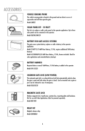
... entering a 4-digit code on a specially designed keypad. Model LD7LP VEHICLE SENSING PROBE The vehicle sensing probe is 40 feet of LiftMaster Security✚® and Passport™ remote controls to 4-button, visor or key chain. Model SOLPNL10W12V BATTERY FOR GATE ACCESS SYSTEMS... it approaches and will then open and locks when the gate is to replace or add a solar panel to control the operator. Single-button to satisfy your authorized LiftMaster dealer for dual gate applications. Model G65ME120C5 REMOTE CONTROLS Chamberlain offers a variety of interconnecting cable required...
... entering a 4-digit code on a specially designed keypad. Model LD7LP VEHICLE SENSING PROBE The vehicle sensing probe is 40 feet of LiftMaster Security✚® and Passport™ remote controls to 4-button, visor or key chain. Model SOLPNL10W12V BATTERY FOR GATE ACCESS SYSTEMS... it approaches and will then open and locks when the gate is to replace or add a solar panel to control the operator. Single-button to satisfy your authorized LiftMaster dealer for dual gate applications. Model G65ME120C5 REMOTE CONTROLS Chamberlain offers a variety of interconnecting cable required...
RSL12V User Manual
Page 7
...lock that automatically unlocks when the gate is open the gate. Model MG1300 OPEN CLOSE RELAY KIT OPEN Maglock release relay. Ideal for use with Solar Applications. Model SGLOCK12V MAGNETIC GATE LOCK Outdoor magnetic lock, transformer, junction box, mounting plate and hardware. CLOSE Model Q400MAU OPEN 6 CLOSE Model...and extended battery backup) BATTERY HARNESS Required when a second 7 AMP-Hour, 12 Vdc battery is to replace or add a solar panel to three solar panels can be released in the ground and can detect a car as it approaches and will then open and locks when the...
...lock that automatically unlocks when the gate is open the gate. Model MG1300 OPEN CLOSE RELAY KIT OPEN Maglock release relay. Ideal for use with Solar Applications. Model SGLOCK12V MAGNETIC GATE LOCK Outdoor magnetic lock, transformer, junction box, mounting plate and hardware. CLOSE Model Q400MAU OPEN 6 CLOSE Model...and extended battery backup) BATTERY HARNESS Required when a second 7 AMP-Hour, 12 Vdc battery is to replace or add a solar panel to three solar panels can be released in the ground and can detect a car as it approaches and will then open and locks when the...
RSL12V Wiring Diagram Manual
Page 1
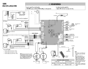
..._ Cr CTRL f ,M, •o O Shadow Loop 1)- 1 Interrupt Loop e 040) 0 Chassis Ground Ground Rod Battery Chassis Ground Red Transformer Block OR Solar Panel (Optional) POWER WIRE (STRANDED COPPER WIRE) 500 feet or less 500 feet to 1000 feet Wire Gauge 14 - 500 feet (152 m) Wire Gauge...- 250mA • Transformer distance is not groundedproperly the range ofthe remote controls willbe reduced. • Allpower wiringshouldbe on - SLIDE RSL12V & RSL12VH ®WARNING To protect against fire: • Replace ONLY with fuse of wire installation. The transformer must be reviewed...
..._ Cr CTRL f ,M, •o O Shadow Loop 1)- 1 Interrupt Loop e 040) 0 Chassis Ground Ground Rod Battery Chassis Ground Red Transformer Block OR Solar Panel (Optional) POWER WIRE (STRANDED COPPER WIRE) 500 feet or less 500 feet to 1000 feet Wire Gauge 14 - 500 feet (152 m) Wire Gauge...- 250mA • Transformer distance is not groundedproperly the range ofthe remote controls willbe reduced. • Allpower wiringshouldbe on - SLIDE RSL12V & RSL12VH ®WARNING To protect against fire: • Replace ONLY with fuse of wire installation. The transformer must be reviewed...

RSL12V Wiring Diagram Manual
Page 2
Wires are madelocally to the terminalblock. NOTE: Do notuse amaglodc anda solenoidlock on the same installation. • Magi ck Power Supply COM White NC Block NO Red R lay Adapter Mod le Marra Re --r-- For continued protection against fire and electrocution: • DISCONNECT power and battery BEFORE installing or servicing operator. bit Automatic Gate Lock (Optional) Coaxial Cable Antenna 0 Maglock w/External Power Supply (Optional) Block L Red Gate 1 (Primary) RPM Sensor Motor NC NO COM Gate 2 (Secondary) NC NO 0 COM Dual Gate Wiring Kit RPM Sensor NOTE...
Wires are madelocally to the terminalblock. NOTE: Do notuse amaglodc anda solenoidlock on the same installation. • Magi ck Power Supply COM White NC Block NO Red R lay Adapter Mod le Marra Re --r-- For continued protection against fire and electrocution: • DISCONNECT power and battery BEFORE installing or servicing operator. bit Automatic Gate Lock (Optional) Coaxial Cable Antenna 0 Maglock w/External Power Supply (Optional) Block L Red Gate 1 (Primary) RPM Sensor Motor NC NO COM Gate 2 (Secondary) NC NO 0 COM Dual Gate Wiring Kit RPM Sensor NOTE...


