MT5011E Installation Manual
Page 5
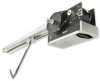
... were provided. 15 1 14 ^ ^OPEN CLOSE O STOP 8 4 10 9 7 2 12 3 13 11 6 5 ITEM DESCRIPTION QTY 1 Operator 1 2 Track (left & right) Door height plus 2' 2 3 Track Spacers 2 4 Front Idler 1 5 Trolley 1 6 Take-up Bolt 1 7 Chain 1 8 Master Links 2 9 Header Bracket 1 10 Header Pivot Shaft 1 11 Curved Door Arm 1 12 Straight Arm 1 13 Door Bracket 1 14 3-Button Station...
... were provided. 15 1 14 ^ ^OPEN CLOSE O STOP 8 4 10 9 7 2 12 3 13 11 6 5 ITEM DESCRIPTION QTY 1 Operator 1 2 Track (left & right) Door height plus 2' 2 3 Track Spacers 2 4 Front Idler 1 5 Trolley 1 6 Take-up Bolt 1 7 Chain 1 8 Master Links 2 9 Header Bracket 1 10 Header Pivot Shaft 1 11 Curved Door Arm 1 12 Straight Arm 1 13 Door Bracket 1 14 3-Button Station...
MT5011E Installation Manual
Page 6
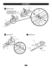
For doors up to 12' use 2 track spacers, for 14' doors use 3 spacers. ASSEMBLY 1 Install track spacers Position the track spacers evenly over the length of the track using the pre-punched holes. Track Spacers Header End Flange Hex Nut Bolt 3/8" - 16 x 3/4" Track Operator End Bolt 3/8" - 16 x 3/4" Flange Hex Nut 2 Install front idler Front Idler Header End Track Bolt 3/8" -16 x 1" Lock Washer Header End Lock Washer Bolt 3/8" -16 x 1" 3 Assemble trolley Trolley Flange Nut 3/8" - 16 Take-Up Bolt Flange Nut 3/8" - 16 Lock Washer 6
For doors up to 12' use 2 track spacers, for 14' doors use 3 spacers. ASSEMBLY 1 Install track spacers Position the track spacers evenly over the length of the track using the pre-punched holes. Track Spacers Header End Flange Hex Nut Bolt 3/8" - 16 x 3/4" Track Operator End Bolt 3/8" - 16 x 3/4" Flange Hex Nut 2 Install front idler Front Idler Header End Track Bolt 3/8" -16 x 1" Lock Washer Header End Lock Washer Bolt 3/8" -16 x 1" 3 Assemble trolley Trolley Flange Nut 3/8" - 16 Take-Up Bolt Flange Nut 3/8" - 16 Lock Washer 6

MT5011E Installation Manual
Page 7
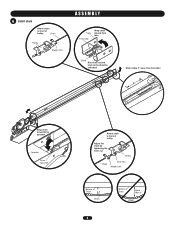
4 Slide trolley onto the track ASSEMBLY Track Operator End Track Trolley Operator End Trolley 5 Attach track to operator Flange Hex Nut Track Flange Hex Nut Bolt 3/8" - 16 x 3/4" Operator End Bolt 3/8" - 16 x 3/4" Operator 7 Header End Bolt 3/8" - 16 x 3/4" Flange Hex Nut Bolt 3/8" - 16 x 3/4"
4 Slide trolley onto the track ASSEMBLY Track Operator End Track Trolley Operator End Trolley 5 Attach track to operator Flange Hex Nut Track Flange Hex Nut Bolt 3/8" - 16 x 3/4" Operator End Bolt 3/8" - 16 x 3/4" Operator 7 Header End Bolt 3/8" - 16 x 3/4" Flange Hex Nut Bolt 3/8" - 16 x 3/4"
MT5011E Installation Manual
Page 8
6 Install chain Attach chain to front of trolley Chain Trolley Master Link ASSEMBLY Track Front Idler Wrap chain around front idler Chain Run chain around track in the direction indicated Slide trolley 2" away from front idler 2" Wrap chain around drive sprocket Operator Drive Sprocket Attach chain to back of trolley Adjust the chain by tightening the inner nut Trolley Chain Inner Nut Master Link Bottom of Track 3" Chain 8 Bottom of Track More than 3" Chain
6 Install chain Attach chain to front of trolley Chain Trolley Master Link ASSEMBLY Track Front Idler Wrap chain around front idler Chain Run chain around track in the direction indicated Slide trolley 2" away from front idler 2" Wrap chain around drive sprocket Operator Drive Sprocket Attach chain to back of trolley Adjust the chain by tightening the inner nut Trolley Chain Inner Nut Master Link Bottom of Track 3" Chain 8 Bottom of Track More than 3" Chain

MT5011E Installation Manual
Page 9
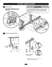
... springs require center mounting. 1 Mark the center of the door Mark the center line of Door Travel 9 TYPICAL INSTALLATION DETERMINE HEADER BRACKET MOUNTING LOCATION The trolley operator is generally mounted over the center of door stile / top section support. However, off center on torsion spring doors.
... springs require center mounting. 1 Mark the center of the door Mark the center line of Door Travel 9 TYPICAL INSTALLATION DETERMINE HEADER BRACKET MOUNTING LOCATION The trolley operator is generally mounted over the center of door stile / top section support. However, off center on torsion spring doors.
MT5011E Installation Manual
Page 11
..., fasten it SECURELY to door manufacturer's instructions for recommended installation guidelines. 11 Lock Nut Washer Bolt (Not Provided) Bolt (Not Provided) 7 Attach door arm to trolley and door AVERTISSEMENT Bolt Nut (Not Provided) ATTENTION Lock Washer Nut Lock Washer Flange Hex Nut NOTICE Straight Door Arm Bolt 3/8-16 x 3/4 Curved Door Arm...
..., fasten it SECURELY to door manufacturer's instructions for recommended installation guidelines. 11 Lock Nut Washer Bolt (Not Provided) Bolt (Not Provided) 7 Attach door arm to trolley and door AVERTISSEMENT Bolt Nut (Not Provided) ATTENTION Lock Washer Nut Lock Washer Flange Hex Nut NOTICE Straight Door Arm Bolt 3/8-16 x 3/4 Curved Door Arm...

MT5011E Installation Manual
Page 21
... wiring the remote control will open .) 2. Emergency Release Handle TO DISCONNECT DOOR FROM OPENER TO RECONNECT DOOR ARM TO TROLLEY AVERTISSEMENT Emergency Disconnect Door Arm Emergency ATTENTION Pull emergency Disconnect release handle straight down. Press the CLOSE button. The door ... from electrocution, disconnect ALL electric power BEFORE performing ANY maintenance. TEST REMOTE CONTROL * Requires B2 wiring type and compatible LiftMaster remote control. Allow the door to fully open door falling rapidly and/or unexpectedly. • NEVER use emergency release handle...
... wiring the remote control will open .) 2. Emergency Release Handle TO DISCONNECT DOOR FROM OPENER TO RECONNECT DOOR ARM TO TROLLEY AVERTISSEMENT Emergency Disconnect Door Arm Emergency ATTENTION Pull emergency Disconnect release handle straight down. Press the CLOSE button. The door ... from electrocution, disconnect ALL electric power BEFORE performing ANY maintenance. TEST REMOTE CONTROL * Requires B2 wiring type and compatible LiftMaster remote control. Allow the door to fully open door falling rapidly and/or unexpectedly. • NEVER use emergency release handle...
MT5011E Installation Manual
Page 22
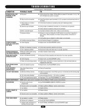
... balanced properly ➤ Verify brake assembly operation and wiring. ➤ Disconnect trolley and check door for proper operation. ➤ Check 3-button control wiring. ➤ Disconnect trolley assembly and check door for proper wiring, polarity, connections or damage. RADIO ...more than 5 seconds. REMOTE CANNOT BE LEARNED B) Remote control not compatible C) Low battery A) Low battery ➤ Obtain qualified LiftMaster remote control device. ➤ Replace battery. ➤ Replace battery. If door closes, check accessory for proper operation. TTC will ...
... balanced properly ➤ Verify brake assembly operation and wiring. ➤ Disconnect trolley and check door for proper operation. ➤ Check 3-button control wiring. ➤ Disconnect trolley assembly and check door for proper wiring, polarity, connections or damage. RADIO ...more than 5 seconds. REMOTE CANNOT BE LEARNED B) Remote control not compatible C) Low battery A) Low battery ➤ Obtain qualified LiftMaster remote control device. ➤ Replace battery. ➤ Replace battery. If door closes, check accessory for proper operation. TTC will ...
MT5011E Installation Manual
Page 26
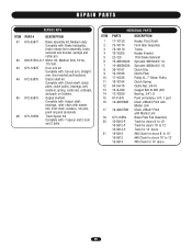
...-P-075 19-48033MB 19-48027MB K75-10359 10-5810-P 10-5812-P 10-5814-P 19-5810 19-5812 19-5814 Header Pivot Shaft Front Idler Assembly Trolley Header Bracket 115V Brake Solenoid Sprocket 48B10x3/4" I .D. Clutch Disc Clutch Plate Pulley 4L, 7" Motor Pulley Clutch Spring Castle Nut, 3/4-16 Cogged Belt 4L290 (29") Bearing...
...-P-075 19-48033MB 19-48027MB K75-10359 10-5810-P 10-5812-P 10-5814-P 19-5810 19-5812 19-5814 Header Pivot Shaft Front Idler Assembly Trolley Header Bracket 115V Brake Solenoid Sprocket 48B10x3/4" I .D. Clutch Disc Clutch Plate Pulley 4L, 7" Motor Pulley Clutch Spring Castle Nut, 3/4-16 Cogged Belt 4L290 (29") Bearing...
MT5011E QuickStart Guide Manual
Page 2
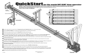
Visit www.LiftMaster.com to locate a professional installing dealer in the installation manual. 01-34216B &#...Slo4t 4 Clutch POWER WIRING 9 12 Pow1e1rhead Because each track. (Four -3/4" bolts/nuts) 5 Connect the chain to the trolley carriage connection on the door end. If the track is longer than 15', use of a mid-span support bracket is unique...Install the spacer brackets evenly down the track. Then use . BHreaacdke6ert 2 1st 2nd 5 QuickStart for the model MT/BMT door operator IMPORTANT: This QuickStart is safe for its intended use the pivot shaft and cotter pins to ...
Visit www.LiftMaster.com to locate a professional installing dealer in the installation manual. 01-34216B &#...Slo4t 4 Clutch POWER WIRING 9 12 Pow1e1rhead Because each track. (Four -3/4" bolts/nuts) 5 Connect the chain to the trolley carriage connection on the door end. If the track is longer than 15', use of a mid-span support bracket is unique...Install the spacer brackets evenly down the track. Then use . BHreaacdke6ert 2 1st 2nd 5 QuickStart for the model MT/BMT door operator IMPORTANT: This QuickStart is safe for its intended use the pivot shaft and cotter pins to ...

