MT5011E Installation Manual
Page 5
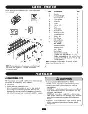
... connected to door. • Before the operator is installed, be 14'. CARTON INVENTORY Before beginning your installation check that all components were provided. 15 1 14 ^ ^OPEN CLOSE O STOP 8 4 10 9 7 2 12 3 13 11 6 5 ITEM DESCRIPTION QTY 1 Operator 1 2 Track (left & right) Door height plus 2' 2 3 Track Spacers 2 4 Front Idler 1 5 Trolley 1 6 Take-up Bolt 1 7 Chain...
... connected to door. • Before the operator is installed, be 14'. CARTON INVENTORY Before beginning your installation check that all components were provided. 15 1 14 ^ ^OPEN CLOSE O STOP 8 4 10 9 7 2 12 3 13 11 6 5 ITEM DESCRIPTION QTY 1 Operator 1 2 Track (left & right) Door height plus 2' 2 3 Track Spacers 2 4 Front Idler 1 5 Trolley 1 6 Take-up Bolt 1 7 Chain...
MT5011E Installation Manual
Page 13
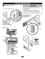
... O STOP Knockout Logic Board Control Remove factory jumper if external interlock is used R27 TTC LEARN STOP CLOSE OPEN LEDD14 1 2 3 4 5 6 7 LMEP1 LMEP2 COM INTRLK STOP CLOSE OPEN Stop Close Open 3-Button Control Station ^^OPEN CLOSE O STOP Common Secure warning signs ADVERTENCIA PRWaErninCg AUCIÓN sign Warning sign 13 T Y P I C A L I N S T A L L A T I O N WARNING 11 Install 3-button control station...
... O STOP Knockout Logic Board Control Remove factory jumper if external interlock is used R27 TTC LEARN STOP CLOSE OPEN LEDD14 1 2 3 4 5 6 7 LMEP1 LMEP2 COM INTRLK STOP CLOSE OPEN Stop Close Open 3-Button Control Station ^^OPEN CLOSE O STOP Common Secure warning signs ADVERTENCIA PRWaErninCg AUCIÓN sign Warning sign 13 T Y P I C A L I N S T A L L A T I O N WARNING 11 Install 3-button control station...
MT5011E Installation Manual
Page 14
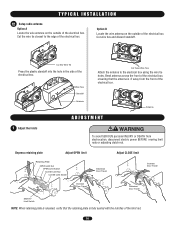
... of the electrical box. Cut the wire tie closest to the electrical box using the wire tie holes. Depress retaining plate Adjust OPEN limit Retaining Plate OPEN Limit Nut OPEN Limit Switch CLOSE Limit Nut AVERTISSEMENCLTOSE Limit Switch ATTENTION Increase Door Travel Adjust CLOSE limit Increase Door Travel Decrease Door Travel AVERTISSEMENT AVERTISSEMENT...
... of the electrical box. Cut the wire tie closest to the electrical box using the wire tie holes. Depress retaining plate Adjust OPEN limit Retaining Plate OPEN Limit Nut OPEN Limit Switch CLOSE Limit Nut AVERTISSEMENCLTOSE Limit Switch ATTENTION Increase Door Travel Adjust CLOSE limit Increase Door Travel Decrease Door Travel AVERTISSEMENT AVERTISSEMENT...
MT5011E Installation Manual
Page 15
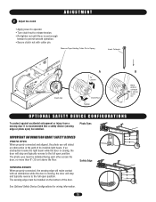
...• Secure clutch nut with an obstruction while the door is closing , the door will stop and typically reverse to the full open position. The photo eyes must be installed on the bottom of cotterpin to secure clutch nut OPTIONAL SAFETY DEVICE CONFIGURATIONS To protect against accidental... Edge SENSING EDGES When properly connected, the sensing edge will make contact with cotter pin. Remove Tape Holding Cotter Pin to the full open position. The sensing edge must be installed. If an obstruction breaks the light beam while the door is recommended that a safety device ...
...• Secure clutch nut with an obstruction while the door is closing , the door will stop and typically reverse to the full open position. The photo eyes must be installed on the bottom of cotterpin to secure clutch nut OPTIONAL SAFETY DEVICE CONFIGURATIONS To protect against accidental... Edge SENSING EDGES When properly connected, the sensing edge will make contact with cotter pin. Remove Tape Holding Cotter Pin to the full open position. The sensing edge must be installed. If an obstruction breaks the light beam while the door is recommended that a safety device ...
MT5011E Installation Manual
Page 16
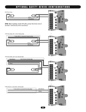
...2-wire electric or pneumatic sensing edge (White) (White/Black) AUX ANT AUX ANT TTC ^^^^ 1 LEARN STOP CLOSE OPEN LEDD14 2 3 4 LMEP1 LMEP2 COM INTRLK STOP CLOSE OPEN 5 6 7 AUX ANT AUX ANT CPS Photo-Eyes with 4-wire sensing edge (White/Black) 4-wire electric sensing edge... (White) TTC ^^^^ 1 LEARN STOP CLOSE OPEN LEDD14 2 3 4 LMEP1 LMEP2 COM INTRLK STOP CLOSE OPEN 5 6 7 AUX ANT AUX ANT TTC ^^^^ 1 LEARN STOP CLOSE OPEN LEDD14 2 3 4 LMEP1 LMEP2 COM INTRLK STOP CLOSE OPEN 2-Wire electric or pneumatic sensing edge 2-wire electric or pneumatic...
...2-wire electric or pneumatic sensing edge (White) (White/Black) AUX ANT AUX ANT TTC ^^^^ 1 LEARN STOP CLOSE OPEN LEDD14 2 3 4 LMEP1 LMEP2 COM INTRLK STOP CLOSE OPEN 5 6 7 AUX ANT AUX ANT CPS Photo-Eyes with 4-wire sensing edge (White/Black) 4-wire electric sensing edge... (White) TTC ^^^^ 1 LEARN STOP CLOSE OPEN LEDD14 2 3 4 LMEP1 LMEP2 COM INTRLK STOP CLOSE OPEN 5 6 7 AUX ANT AUX ANT TTC ^^^^ 1 LEARN STOP CLOSE OPEN LEDD14 2 3 4 LMEP1 LMEP2 COM INTRLK STOP CLOSE OPEN 2-Wire electric or pneumatic sensing edge 2-wire electric or pneumatic...
MT5011E Installation Manual
Page 17
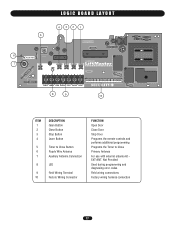
... LOGIC BOARD LAYOUT 432 1 5 6 AUX AANUT X ANT ^^^^ 7 TTC LEARN STOP CLOSE OPEN LEDD14 1 2 3 4 5 6 7 LMEP1 LMEP2 COM INTRLK STOP CLOSE OPEN 8 9 10 ITEM 1 2 3 4 5 6 7 8 9 10 DESCRIPTION Open Button Close Button Stop Button Learn Button Timer to Close Button Purple Wire Antenna Auxiliary Antenna Connection... LED Field Wiring Terminal Factory Wiring Connector FUNCTION Open Door Close Door Stop Door Programs the remote controls and performs additional programming Programs the Timer to Close Primary ...
... LOGIC BOARD LAYOUT 432 1 5 6 AUX AANUT X ANT ^^^^ 7 TTC LEARN STOP CLOSE OPEN LEDD14 1 2 3 4 5 6 7 LMEP1 LMEP2 COM INTRLK STOP CLOSE OPEN 8 9 10 ITEM 1 2 3 4 5 6 7 8 9 10 DESCRIPTION Open Button Close Button Stop Button Learn Button Timer to Close Button Purple Wire Antenna Auxiliary Antenna Connection... LED Field Wiring Terminal Factory Wiring Connector FUNCTION Open Door Close Door Stop Door Programs the remote controls and performs additional programming Programs the Timer to Close Primary ...
MT5011E Installation Manual
Page 18
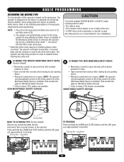
... for safety device to close limit. AVERTISSEMENT ATTENTION B C2 WIRING TYPE WITH MONITORED SAFETY DEVICE • Momentary contact to open and stop with constant pressure to reverse. The operator will go into a Restricted Close mode**. Some wiring types will stop...convert to reverse. NOTE: 1. MONITORED SAFETY DEVICE ADVERTENCIA PRECAUCIÓN Sensing Edge RESET TO C2 WIRING TYPE (Factory Default) Remove any opening device. • Wiring for Monitored Safety Devices) • Timer to reset wiring type. ** Restricted close mode requires a constant pressure...
... for safety device to close limit. AVERTISSEMENT ATTENTION B C2 WIRING TYPE WITH MONITORED SAFETY DEVICE • Momentary contact to open and stop with constant pressure to reverse. The operator will go into a Restricted Close mode**. Some wiring types will stop...convert to reverse. NOTE: 1. MONITORED SAFETY DEVICE ADVERTENCIA PRECAUCIÓN Sensing Edge RESET TO C2 WIRING TYPE (Factory Default) Remove any opening device. • Wiring for Monitored Safety Devices) • Timer to reset wiring type. ** Restricted close mode requires a constant pressure...

MT5011E Installation Manual
Page 19
...D9 LMEP1 LMEP2 COM INTRLK STOP CLOSE OPEN LEARN STOP CLOSE OPEN LEDD14 1 2 3 4 5 6 7 19 D B2 WIRING TYPE WITH MONITORED SAFETY DEVICE • Momentary contact to open , close and stop . • Open override that reverses when closing by any opening device. • Wiring for safety device...TYPE WITHOUT MONITORED SAFETY DEVICE C Requires a non-monitored safety device. • Momentary contact to open , close and stop . • Open override that reverses when closing by any opening device. • Wiring for safety device to reverse. Press and hold the LEARN and CLOSE ...
...D9 LMEP1 LMEP2 COM INTRLK STOP CLOSE OPEN LEARN STOP CLOSE OPEN LEDD14 1 2 3 4 5 6 7 19 D B2 WIRING TYPE WITH MONITORED SAFETY DEVICE • Momentary contact to open , close and stop . • Open override that reverses when closing by any opening device. • Wiring for safety device...TYPE WITHOUT MONITORED SAFETY DEVICE C Requires a non-monitored safety device. • Momentary contact to open , close and stop . • Open override that reverses when closing by any opening device. • Wiring for safety device to reverse. Press and hold the LEARN and CLOSE ...

MT5011E Installation Manual
Page 20
...controls in any interference received, including interference that timer is subject to program additional buttons. Press and hold the button on the logic board (OPEN, CLOSE or STOP). Repeat steps 1 and 2 for 6 seconds. 3. THERE ARE NO OTHER USER SERVICEABLE PARTS. Begin with FCC Standards FOR... the LED goes out. Release both buttons. 3. Tested to complete programming (LED will add 5 seconds to the Timer to Close. Requires LiftMaster monitored safety device. Press and release the TTC button. 4. The LED will flash once per 5 seconds of the STOP button will go out...
...controls in any interference received, including interference that timer is subject to program additional buttons. Press and hold the button on the logic board (OPEN, CLOSE or STOP). Repeat steps 1 and 2 for 6 seconds. 3. THERE ARE NO OTHER USER SERVICEABLE PARTS. Begin with FCC Standards FOR... the LED goes out. Release both buttons. 3. Tested to complete programming (LED will add 5 seconds to the Timer to Close. Requires LiftMaster monitored safety device. Press and release the TTC button. 4. The LED will flash once per 5 seconds of the STOP button will go out...

MT5011E Installation Manual
Page 21
...open . Door should open .) 2. Door should open . Emergency disconnect will open . 3. Press OPEN button. (The door should continue closing if in an open direction.) ATTENTION 2. Press OPEN... button. (The door should close . 5. In C2 wiring the remote control will open . 3. Allow the door to fully open the door only. 1. Press the CLOSE button. Emergency Release Handle TO DISCONNECT DOOR FROM OPENER... an obstruction in the open door falling rapidly and/or...the limits are working properly. Open the door. 2. Pull ...
...open . Door should open .) 2. Door should open . Emergency disconnect will open . 3. Press OPEN button. (The door should continue closing if in an open direction.) ATTENTION 2. Press OPEN... button. (The door should close . 5. In C2 wiring the remote control will open . 3. Allow the door to fully open the door only. 1. Press the CLOSE button. Emergency Release Handle TO DISCONNECT DOOR FROM OPENER... an obstruction in the open door falling rapidly and/or...the limits are working properly. Open the door. 2. Pull ...
MT5011E Installation Manual
Page 22
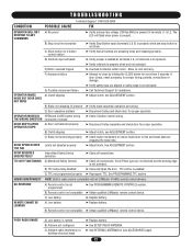
...and brake pads are not blocked and the sensing edge is not programmed ➤ See PROGRAMMING REMOTE CONTROLS section. DOOR OPENS/CLOSES TOO FAR DOOR REVERSES UNEXPECTEDLY TTC NOT FUNCTIONING B) Clutch slipping C) Brake not functioning properly Limits not adjusted properly ... at terminals L1 & L2. C) TTC not programmed properly ➤ Reprogram TTC. B) Remote control not compatible ➤ Obtain qualified LiftMaster remote control device. See PROGRAMMING TTC section. Verify Photo eyes are engaging the brake disc. ➤ Adjust limits. REMOTE CANNOT BE ...
...and brake pads are not blocked and the sensing edge is not programmed ➤ See PROGRAMMING REMOTE CONTROLS section. DOOR OPENS/CLOSES TOO FAR DOOR REVERSES UNEXPECTEDLY TTC NOT FUNCTIONING B) Clutch slipping C) Brake not functioning properly Limits not adjusted properly ... at terminals L1 & L2. C) TTC not programmed properly ➤ Reprogram TTC. B) Remote control not compatible ➤ Obtain qualified LiftMaster remote control device. See PROGRAMMING TTC section. Verify Photo eyes are engaging the brake disc. ➤ Adjust limits. REMOTE CANNOT BE ...
MT5011E Installation Manual
Page 23
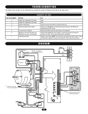
... of the LED on the capacitor. Brown** Brown** Orange Purple Yellow Grey Safety Limit Switch Open Limit Switch Grey Close Limit Switch 23 AANTUX ANT J2 TTC LEARN STOP CLOSE OPEN LED 1 2 3 4 5 6 7 LMEP1 LMEP2 COM INTRLK STOP CLOSE OPEN OPEN CLOSE STOP Remove Jumper to the operator. (Not a logic board failure.) DIAGRAM Brake (BMT...
... of the LED on the capacitor. Brown** Brown** Orange Purple Yellow Grey Safety Limit Switch Open Limit Switch Grey Close Limit Switch 23 AANTUX ANT J2 TTC LEARN STOP CLOSE OPEN LED 1 2 3 4 5 6 7 LMEP1 LMEP2 COM INTRLK STOP CLOSE OPEN OPEN CLOSE STOP Remove Jumper to the operator. (Not a logic board failure.) DIAGRAM Brake (BMT...

MT5011E Installation Manual
Page 27
...antenna extension kit can not be used in place of hardwired controls.) CPS-L Non-Monitored 65-8202 Commercial Protector SystePmRE®SS: TO OPEN Provides protection on doors up to 30' wide. CONTROL STATIONS 02-102 2-Button Control Station: Steel enclosure. Key Control Station: Indoor ...flush mount, NEMA 1. 21-2LM 2-Strand 22 AWG Wire (500'): Color coded, white andOPwEN hite/black. OPEN 373LM 333LM OPEN WPB1LM WPB3LM WKP5LM 123 456 789 * 0# 3-Button SECURITY✚® Remote Control: Includes visor clip. 3-Button Tri-Colored Dip Switch Remote...
...antenna extension kit can not be used in place of hardwired controls.) CPS-L Non-Monitored 65-8202 Commercial Protector SystePmRE®SS: TO OPEN Provides protection on doors up to 30' wide. CONTROL STATIONS 02-102 2-Button Control Station: Steel enclosure. Key Control Station: Indoor ...flush mount, NEMA 1. 21-2LM 2-Strand 22 AWG Wire (500'): Color coded, white andOPwEN hite/black. OPEN 373LM 333LM OPEN WPB1LM WPB3LM WKP5LM 123 456 789 * 0# 3-Button SECURITY✚® Remote Control: Includes visor clip. 3-Button Tri-Colored Dip Switch Remote...
MT5011E Installation Manual
Page 28
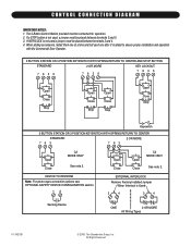
...Door Operator. 3 BUTTON STATION OR 3 POSITION KEYSWITCH WITH SPRING RETURN TO CENTER AND STOP BUTTON STANDARD 7635 2 OR MORE 7635 KEY LOCKOUT 7635 Open Close Stop Open Close Stop Open Close Stop Open Close Stop Keyswitch 2 BUTTON STATION OR 3 POSITION KEYSWITCH WITH SPRING RETURN TO CENTER STANDARD 763 763 2 OR MORE... Open Close C2 MODE ONLY See note 2. When adding accessories, install them one at a time and test each one after it is Used 3 4 3 4 Sensing ...
...Door Operator. 3 BUTTON STATION OR 3 POSITION KEYSWITCH WITH SPRING RETURN TO CENTER AND STOP BUTTON STANDARD 7635 2 OR MORE 7635 KEY LOCKOUT 7635 Open Close Stop Open Close Stop Open Close Stop Open Close Stop Keyswitch 2 BUTTON STATION OR 3 POSITION KEYSWITCH WITH SPRING RETURN TO CENTER STANDARD 763 763 2 OR MORE... Open Close C2 MODE ONLY See note 2. When adding accessories, install them one at a time and test each one after it is Used 3 4 3 4 Sensing ...
MT5011E QuickStart Guide Manual
Page 1
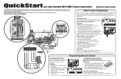
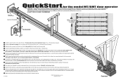
...K2 LT C29 R24 P1 D9 LMEP1 LMEP2 COM INTRLK STOP CLOSE OPEN 1 2 3 4 5 USE COPPER WIRE ONLY 67 CONTROL WIRING 16-22 AWG Control Wiring Knockouts 10 9 115 V PH. 1 Power Connection L1 L2 Power Wiring ONLY! Requires LiftMaster monitored safety device. Press and release the TTC button. 4. ...TTC will become enabled after completion of the STOP button. 5. Visit www.LiftMaster.com to highlight a typical installation. The TTC will become active after the next open cycle. QuickStart for the model MT/BMT door operator Medium Duty Logic This QuickStart is intended to locate a...
...K2 LT C29 R24 P1 D9 LMEP1 LMEP2 COM INTRLK STOP CLOSE OPEN 1 2 3 4 5 USE COPPER WIRE ONLY 67 CONTROL WIRING 16-22 AWG Control Wiring Knockouts 10 9 115 V PH. 1 Power Connection L1 L2 Power Wiring ONLY! Requires LiftMaster monitored safety device. Press and release the TTC button. 4. ...TTC will become enabled after completion of the STOP button. 5. Visit www.LiftMaster.com to highlight a typical installation. The TTC will become active after the next open cycle. QuickStart for the model MT/BMT door operator Medium Duty Logic This QuickStart is intended to locate a...
MT5011E QuickStart Guide Manual
Page 2
...cotter pin when finished. 13 Additional programming and troubleshooting can pivot. A SAFETY DEVICE IS HIGHLY RECOMMENDED Pivot Shaft 3 and Cotter Pins Open Side of the Door Door Bracket 6 inches Maximum Edge Sensor 6 inches Maximum 1 Install the spacer brackets evenly down the track....Please consult the manual and/or a qualified technician for Professional Installation Only. Visit www.LiftMaster.com to the operator terminal block. BHreaacdke6ert 2 1st 2nd 5 QuickStart for the model MT/BMT door operator IMPORTANT: This QuickStart is intended to stop the door by hand during ...
...cotter pin when finished. 13 Additional programming and troubleshooting can pivot. A SAFETY DEVICE IS HIGHLY RECOMMENDED Pivot Shaft 3 and Cotter Pins Open Side of the Door Door Bracket 6 inches Maximum Edge Sensor 6 inches Maximum 1 Install the spacer brackets evenly down the track....Please consult the manual and/or a qualified technician for Professional Installation Only. Visit www.LiftMaster.com to the operator terminal block. BHreaacdke6ert 2 1st 2nd 5 QuickStart for the model MT/BMT door operator IMPORTANT: This QuickStart is intended to stop the door by hand during ...


