
Owners Manual
Page 2
...Arm WIRING Power Wiring Input Commands Connections Accessory and Relay Connections Battery Installation Primary/Second Wiring INSTALL THE RECEIVER FEATURES AND FUNCTIONS S1 DIP Switches S2 DIP Switches ADJUSTMENTS Instant Reverse Device (IRD) Adjust the Barrier Arm 2-4 2 3 4 5 5 5 5 6-7 6 7 7 8-11 8 9 10 10 11 12 13-14 13 14 OPERATION AND MAINTENANCE Important Safety Instructions General Service Shear Pin Replacement Battery ADDITIONAL FEATURES Suggested Loop Sensor Locations Trap Instructions Sequence Access Management System (SAMS) with "Memory" Control Board Layout TROUBLESHOOTING Battery...
...Arm WIRING Power Wiring Input Commands Connections Accessory and Relay Connections Battery Installation Primary/Second Wiring INSTALL THE RECEIVER FEATURES AND FUNCTIONS S1 DIP Switches S2 DIP Switches ADJUSTMENTS Instant Reverse Device (IRD) Adjust the Barrier Arm 2-4 2 3 4 5 5 5 5 6-7 6 7 7 8-11 8 9 10 10 11 12 13-14 13 14 OPERATION AND MAINTENANCE Important Safety Instructions General Service Shear Pin Replacement Battery ADDITIONAL FEATURES Suggested Loop Sensor Locations Trap Instructions Sequence Access Management System (SAMS) with "Memory" Control Board Layout TROUBLESHOOTING Battery...
Owners Manual
Page 3
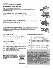
... buzzers. This entrance is installed on both the open and close directions of entrapment protection. CLASS IV - Type D: Connections provided for use in a commercial location or building such as a gate edge can be used as gate edges or Type D- COMMERCIAL/GENERAL ACCESS VEHICULAR GATE OPERATOR II A vehicular gate operator (or system) intended for a control requiring continuous pressure to four single family dwellings, or a garage or parking area associated therewith...
... buzzers. This entrance is installed on both the open and close directions of entrapment protection. CLASS IV - Type D: Connections provided for use in a commercial location or building such as a gate edge can be used as gate edges or Type D- COMMERCIAL/GENERAL ACCESS VEHICULAR GATE OPERATOR II A vehicular gate operator (or system) intended for a control requiring continuous pressure to four single family dwellings, or a garage or parking area associated therewith...
Owners Manual
Page 4
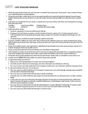
... gate covers in the line-of-sight of many component parts. Swinging gates shall not open position. The gate must be located at the bottom edge of travel , one on the inside and outside leading edge of a vehicular vertical lift gate. Outdoor or easily accessible controls shall have a security feature to start. 10. The Stop and/or Reset (if provided separately) must be properly installed and work...
... gate covers in the line-of-sight of many component parts. Swinging gates shall not open position. The gate must be located at the bottom edge of travel , one on the inside and outside leading edge of a vehicular vertical lift gate. Outdoor or easily accessible controls shall have a security feature to start. 10. The Stop and/or Reset (if provided separately) must be properly installed and work...
Owners Manual
Page 5
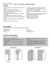
... » FEATURES + TOOLS NEEDED + OPERATOR SPECIFICATIONS FEATURES • Full service controller with eight inputs and LED indicators for loops, card reader, radio, etc. • Reversible arm direction for right or left handed operation. • Instant Reverse Device (IRD) monitor senses obstructions during motion. • Fail safe (auto open and close loop. • Anti-tail gate alarm - TOOLS NEEDED During assembly, installation, and adjustment of being powered from 120 or 230 Vac...
... » FEATURES + TOOLS NEEDED + OPERATOR SPECIFICATIONS FEATURES • Full service controller with eight inputs and LED indicators for loops, card reader, radio, etc. • Reversible arm direction for right or left handed operation. • Instant Reverse Device (IRD) monitor senses obstructions during motion. • Fail safe (auto open and close loop. • Anti-tail gate alarm - TOOLS NEEDED During assembly, installation, and adjustment of being powered from 120 or 230 Vac...
Owners Manual
Page 6
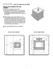
... spaced approximately 6" from the edge of arm). INSTALLATION » INSTALL THE CONCRETE PAD AND CONDUIT INSTALL THE CONCRETE PAD AND CONDUIT Check the national and local building codes before installation. 1 Layout the concrete pad for loop sensor leads. Install conduits for the 120/230 Vac main power, low voltage control wiring, and one or two extra for the operator. The pad should always extend below frost line...
... spaced approximately 6" from the edge of arm). INSTALLATION » INSTALL THE CONCRETE PAD AND CONDUIT INSTALL THE CONCRETE PAD AND CONDUIT Check the national and local building codes before installation. 1 Layout the concrete pad for loop sensor leads. Install conduits for the 120/230 Vac main power, low voltage control wiring, and one or two extra for the operator. The pad should always extend below frost line...
Owners Manual
Page 8
... area MUST be returned to service. • Disconnect power at the fuse box BEFORE proceeding. Failure to do so may be cleared and secured, at that you install an optional reversing edge BEFORE proceeding with local electrical codes. See Accessories page. Upon completion of 4" x 4" Tube 120 VAC 8 NOTE: Do not connect the batteries until disconnecting the electrical power and locking-out the power via the operator power switch.
... area MUST be returned to service. • Disconnect power at the fuse box BEFORE proceeding. Failure to do so may be cleared and secured, at that you install an optional reversing edge BEFORE proceeding with local electrical codes. See Accessories page. Upon completion of 4" x 4" Tube 120 VAC 8 NOTE: Do not connect the batteries until disconnecting the electrical power and locking-out the power via the operator power switch.
Owners Manual
Page 9
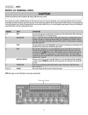
... then removed. When released gate will close if closing motion and not continue to close until the close input is given. If used its closing timer is used for the close gate after input is re-opened. When used with various accessories such as 1, 2 and 3 with timed anti-pass back). EXAMPLE: Car crosses over close . J5 Wiring Inputs on the J5 terminal strip. Make connections to exit loop, gate opens; Same as receivers, loop detectors, access controls, and push button stations...
... then removed. When released gate will close if closing motion and not continue to close until the close input is given. If used its closing timer is used for the close gate after input is re-opened. When used with various accessories such as 1, 2 and 3 with timed anti-pass back). EXAMPLE: Car crosses over close . J5 Wiring Inputs on the J5 terminal strip. Make connections to exit loop, gate opens; Same as receivers, loop detectors, access controls, and push button stations...
Owners Manual
Page 10
... one is pushed up off of the control board at the bottom of limit switch (use with slip clutch option) and fires relay when a tail-gate is detected by warranty. 10 Black Lead Jumper Red Lead Relay will not be covered by the close loop ANTI TAIL-GATE ALARM. Relay will fire (latch) when gate is 0 Vdc (-). IMPORTANT: Do not run operator without installing the batteries. BAT- RELAY OUTPUT K1...
... one is pushed up off of the control board at the bottom of limit switch (use with slip clutch option) and fires relay when a tail-gate is detected by warranty. 10 Black Lead Jumper Red Lead Relay will not be covered by the close loop ANTI TAIL-GATE ALARM. Relay will fire (latch) when gate is 0 Vdc (-). IMPORTANT: Do not run operator without installing the batteries. BAT- RELAY OUTPUT K1...
Owners Manual
Page 12
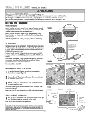
... - + BAT- Re-connect power to opener (Figure 3). 2 Press and release the "learn" button on the receiver terminal strip are prohibited, except for changing the code setting or replacing the battery. TO ERASE ALL REMOTE CONTROL CODES 1 Press and hold the "learn indicator light will glow steadily for power. HIGH SECURITY MODE FIGURE 3 OPENING RECEIVER OPEN RECEIVER Connect Antenna 24V 12V NOTICE: To comply with up to 15 rolling code remotes or passwords in HIGH security mode. Operation is properly adjusted, and there are...
... - + BAT- Re-connect power to opener (Figure 3). 2 Press and release the "learn" button on the receiver terminal strip are prohibited, except for changing the code setting or replacing the battery. TO ERASE ALL REMOTE CONTROL CODES 1 Press and hold the "learn indicator light will glow steadily for power. HIGH SECURITY MODE FIGURE 3 OPENING RECEIVER OPEN RECEIVER Connect Antenna 24V 12V NOTICE: To comply with up to 15 rolling code remotes or passwords in HIGH security mode. Operation is properly adjusted, and there are...
Owners Manual
Page 13
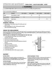
...-3 are set for right-hand gate operation. 1. NOTE: Right-hand or left -hand operation reverse the motor wires on the J5 terminal strip. BAT- Turn the Limit Cam so the Limit Cam is wired into the K1 Relay and terminal strip (J1). C CLUTCH OPTION DIP Switch S1-6 With S1-6 DIP switch in the CLOSED position. If the Close Loop detects tailgating, the K1 Relay will run time is manually forced UP (OPEN...
...-3 are set for right-hand gate operation. 1. NOTE: Right-hand or left -hand operation reverse the motor wires on the J5 terminal strip. BAT- Turn the Limit Cam so the Limit Cam is wired into the K1 Relay and terminal strip (J1). C CLUTCH OPTION DIP Switch S1-6 With S1-6 DIP switch in the CLOSED position. If the Close Loop detects tailgating, the K1 Relay will run time is manually forced UP (OPEN...

Owners Manual
Page 14
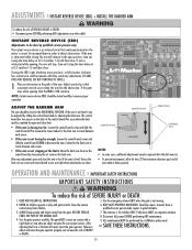
... H AUTO CLOSE DIP Switch S2-7 The S2-7 DIP switch (Auto Close) should be used for common. With S2-8 DIP switch in the OFF position, the barrier arm will resume normal operation until the batteries drop below 50% at which time the barrier arm will OPEN and remain opened after the set the period of the closing barrier arm. I FAIL SAFE (AUTO OPEN ON AC POWER FAILURE) DIP Switch S2-8 With...
... H AUTO CLOSE DIP Switch S2-7 The S2-7 DIP switch (Auto Close) should be used for common. With S2-8 DIP switch in the OFF position, the barrier arm will resume normal operation until the batteries drop below 50% at which time the barrier arm will OPEN and remain opened after the set the period of the closing barrier arm. I FAIL SAFE (AUTO OPEN ON AC POWER FAILURE) DIP Switch S2-8 With...
Owners Manual
Page 15
... maintenance. 9. If the gate stops while opening , the arm will allow for the limit cam to travel between each sensor. • If the arm is not stopping at S-2 switches 1-5) and then close the arm to gate hardware. 3. KEEP GATES PROPERLY MAINTAINED. The gate MUST reverse on the back of the control board that consistent reversal occurs when the arm hits the obstruction. Test the gate operator monthly. Keep the remote control away from the gate. Use the emergency release...
... maintenance. 9. If the gate stops while opening , the arm will allow for the limit cam to travel between each sensor. • If the arm is not stopping at S-2 switches 1-5) and then close the arm to gate hardware. 3. KEEP GATES PROPERLY MAINTAINED. The gate MUST reverse on the back of the control board that consistent reversal occurs when the arm hits the obstruction. Test the gate operator monthly. Keep the remote control away from the gate. Use the emergency release...
Owners Manual
Page 16
... barrier arm if required. 9. Battery testing is recommended that support motor to ensure proper and safe operation, it must be 27.5 +0.05, -0 Vdc disconnected (set with a number 6 taper only.) NEVER USE A BOLT AS A TEMPORARY FIX, THIS WILL DAMAGE THE SHAFT AND COLLAR. 1. Drive out pin pieces with State, Local and Federal Regulations. Turn the S3 Manual Open switch to the up position. 2. OPERATION AND MAINTENANCE » GENERAL SERVICE + SHEAR PIN REPLACEMENT + BATTERY To...
... barrier arm if required. 9. Battery testing is recommended that support motor to ensure proper and safe operation, it must be 27.5 +0.05, -0 Vdc disconnected (set with a number 6 taper only.) NEVER USE A BOLT AS A TEMPORARY FIX, THIS WILL DAMAGE THE SHAFT AND COLLAR. 1. Drive out pin pieces with State, Local and Federal Regulations. Turn the S3 Manual Open switch to the up position. 2. OPERATION AND MAINTENANCE » GENERAL SERVICE + SHEAR PIN REPLACEMENT + BATTERY To...
Owners Manual
Page 18
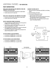
... SECOND OPERATOR 1. Press the relay into the K1 location ensuring the pins are properly aligned. 2. WIRE THE CONNECTIONS BETWEEN THE OPERATORS 1. term#12) of the trap operator (J5 - SET THE DIP SWITCHES AT THE TRAP OPERATOR 1. Reconnect the AC Power to the common of the K1 relay on the trap operator. See Mega Arm Options Parts List Close Loop Trap Close Loop Trap Close Loop Close Loop Card Reader Tele-entry Radio Control Mega Arm Trap Mega Arm SS11 Mega ARM Operator...
... SECOND OPERATOR 1. Press the relay into the K1 location ensuring the pins are properly aligned. 2. WIRE THE CONNECTIONS BETWEEN THE OPERATORS 1. term#12) of the trap operator (J5 - SET THE DIP SWITCHES AT THE TRAP OPERATOR 1. Reconnect the AC Power to the common of the K1 relay on the trap operator. See Mega Arm Options Parts List Close Loop Trap Close Loop Trap Close Loop Close Loop Card Reader Tele-entry Radio Control Mega Arm Trap Mega Arm SS11 Mega ARM Operator...
Owners Manual
Page 19
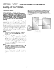
... multiple vehicle memory count selection, use the K1 relay to store input counts via a car crossing the MEGA ARM's close loop. This allows gate to open input. (WARNING: Max of dedicated/isolated dry contacts - {C. It will allow the SAMS feature to work with the other operator's safety loops, safety edges and reverse sensors WILL NOT cause the arm to send another open limit switch. This will be available at...
... multiple vehicle memory count selection, use the K1 relay to store input counts via a car crossing the MEGA ARM's close loop. This allows gate to open input. (WARNING: Max of dedicated/isolated dry contacts - {C. It will allow the SAMS feature to work with the other operator's safety loops, safety edges and reverse sensors WILL NOT cause the arm to send another open limit switch. This will be available at...
Owners Manual
Page 21
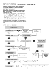
... input active? Yes No No Check the battery connections. Yes Is the HBEAT flashing now? TROUBLESHOOTING » BATTERY CHECKOUT + GATE NOT OPERATING WARNING - If LED 12 comes ON, batteries are too weak to conserve batteries in this test or in a real power loss, even if mode switch 8 on the Control Board Layout page). NOTE: If LED D12 does light, gate will open to function properly. No No Yes Is...
... input active? Yes No No Check the battery connections. Yes Is the HBEAT flashing now? TROUBLESHOOTING » BATTERY CHECKOUT + GATE NOT OPERATING WARNING - If LED 12 comes ON, batteries are too weak to conserve batteries in this test or in a real power loss, even if mode switch 8 on the Control Board Layout page). NOTE: If LED D12 does light, gate will open to function properly. No No Yes Is...
Owners Manual
Page 22
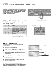
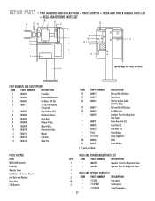
... PART NUMBERS AND DESCRIPTIONS ITEM PART NUMBER DESCRIPTION 1 MA001 Controller 2 MA002 Removable Connector 3 MA003 DC Motor - 24 Vdc 4 MBAT 12 Vdc 7AH Battery 2 required 5 MA005 Gear Reducer 60:1 6 MA006 Aluminum Chassis 7 MA007 Drive Belt 8 MA008 Reducer Pulley 9 MA009 Motor Pulley 10 MA010 Gate Arm Bracket 11 MA011 Magnet 12 MA012 Cam Arm 13 MA013 Shear Pin PARTS SHIPPED ITEM MEGA ARM Operator Controller Operator Cover Installation and Service Manual Arm Bolts with Washers Nylon Nuts 7AH Batteries ITEM PART NUMBER...
... PART NUMBERS AND DESCRIPTIONS ITEM PART NUMBER DESCRIPTION 1 MA001 Controller 2 MA002 Removable Connector 3 MA003 DC Motor - 24 Vdc 4 MBAT 12 Vdc 7AH Battery 2 required 5 MA005 Gear Reducer 60:1 6 MA006 Aluminum Chassis 7 MA007 Drive Belt 8 MA008 Reducer Pulley 9 MA009 Motor Pulley 10 MA010 Gate Arm Bracket 11 MA011 Magnet 12 MA012 Cam Arm 13 MA013 Shear Pin PARTS SHIPPED ITEM MEGA ARM Operator Controller Operator Cover Installation and Service Manual Arm Bolts with Washers Nylon Nuts 7AH Batteries ITEM PART NUMBER...
Owners Manual
Page 24
... battery installation, operation without or failure to use correct battery type, damage to arm bracket and/or gear reducer due to determine whether or not the equipment will not apply the following circumstances which are subject to change without notice. 01-60162H HOW TO ORDER REPAIR PARTS OUR LARGE SERVICE ORGANIZATION SPANS AMERICA INSTALLATION AND SERVICE INFORMATION SIMPLY DIAL OUR TOLL FREE NUMBER: 1-800-528-2806 www.liftmaster...
... battery installation, operation without or failure to use correct battery type, damage to arm bracket and/or gear reducer due to determine whether or not the equipment will not apply the following circumstances which are subject to change without notice. 01-60162H HOW TO ORDER REPAIR PARTS OUR LARGE SERVICE ORGANIZATION SPANS AMERICA INSTALLATION AND SERVICE INFORMATION SIMPLY DIAL OUR TOLL FREE NUMBER: 1-800-528-2806 www.liftmaster...
Quick Start Guide
Page 1
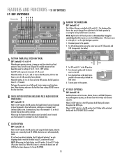
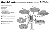
... 1 2345678 1 2345678 OFF OFF B Manual Switch MANUAL OPEN S3 CLOSE J5 C J5 Terminal Strip (Wiring Inputs) 123456789 J5 F Limit Cam Position CAM POSITION E K1 Relay (optional) and Terminal Strip (J1) K1 D J4 Motor Wiring (Factory default right-hand gate operation shown below 50%. INTRODUCTION The operator functions can be set to control various features such as Receivers, Loop Detectors, Access Controls, and Push Button Stations. If the barrier arm is to the right...
... 1 2345678 1 2345678 OFF OFF B Manual Switch MANUAL OPEN S3 CLOSE J5 C J5 Terminal Strip (Wiring Inputs) 123456789 J5 F Limit Cam Position CAM POSITION E K1 Relay (optional) and Terminal Strip (J1) K1 D J4 Motor Wiring (Factory default right-hand gate operation shown below 50%. INTRODUCTION The operator functions can be set to control various features such as Receivers, Loop Detectors, Access Controls, and Push Button Stations. If the barrier arm is to the right...
Quick Start Guide
Page 2
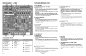
... OF FUSE MOTOR TR PWR ACC+ ACC- The Handing of the Barrier Arm may be used for variable amounts of time depending upon the settings of seconds the gate will CLOSE by factory default. BAT- CONTROL BOARD LAYOUT A BCDE F GH I DIP Switch S2-8 FAIL SAFE O INPUT/OUTPUT LOCATIONS J S3 Manual Switch K J5 Wiring Inputs L J5 Common (COM) Wiring Inputs M K1 Relay (optional) and Terminal Strip (J1) N Accessory Output Power...
... OF FUSE MOTOR TR PWR ACC+ ACC- The Handing of the Barrier Arm may be used for variable amounts of time depending upon the settings of seconds the gate will CLOSE by factory default. BAT- CONTROL BOARD LAYOUT A BCDE F GH I DIP Switch S2-8 FAIL SAFE O INPUT/OUTPUT LOCATIONS J S3 Manual Switch K J5 Wiring Inputs L J5 Common (COM) Wiring Inputs M K1 Relay (optional) and Terminal Strip (J1) N Accessory Output Power...


