
Solar Gate Access System Daily Cycle Chart Manual
Page 1
...,liofolaytanlMsaddardaaenidastcdidpotreetnephdraael®ilasctscIeeaoncmtltetaiehopsrreenspnorsaacer.nityteuTecsrGlhesldeae.rtsareeawwteay and the temperature effects on batteries in an open area clear LAipnon4wo1ve2ar twiSvheoePnloanwereeGrdMeadatnmeaogAsetcmfocerneot spSeysrsatSteinmygstaotegdaemtleivewDrhaileily Cycle Chart of obstructions and shading for the entire day. LA500 Solar Gate Access System Daily Cycle Chart The LA500 Solar Gate Access System utilizes an Solar panel(s) must be located in the given and...
...,liofolaytanlMsaddardaaenidastcdidpotreetnephdraael®ilasctscIeeaoncmtltetaiehopsrreenspnorsaacer.nityteuTecsrGlhesldeae.rtsareeawwteay and the temperature effects on batteries in an open area clear LAipnon4wo1ve2ar twiSvheoePnloanwereeGrdMeadatnmeaogAsetcmfocerneot spSeysrsatSteinmygstaotegdaemtleivewDrhaileily Cycle Chart of obstructions and shading for the entire day. LA500 Solar Gate Access System Daily Cycle Chart The LA500 Solar Gate Access System utilizes an Solar panel(s) must be located in the given and...
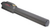
LA500 Manual
Page 4
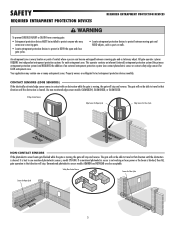
...or B2 In order to complete a proper installation you must have warning signs placed in both sides of the gate to protect against entrapments in plain view on both the open and close directions of entrapment protection you must provide • Type A • Type B1 • ...Type B2 - That means that is prevented via supervision by security personnel. INDUSTRIAL/LIMITED ACCESS VEHICULAR GATE OPERATOR III A vehicular gate operator (or system) ...
...or B2 In order to complete a proper installation you must have warning signs placed in both sides of the gate to protect against entrapments in plain view on both the open and close directions of entrapment protection you must provide • Type A • Type B1 • ...Type B2 - That means that is prevented via supervision by security personnel. INDUSTRIAL/LIMITED ACCESS VEHICULAR GATE OPERATOR III A vehicular gate operator (or system) ...
LA500 Manual
Page 5
... as an edge sensor: a. b. One or more contact sensors shall be located and its wiring arranged so the communication between the gate and adjacent structures when opening and closing to start. 10. A hard wired contact sensor shall be located at the bottom edge of a vertical barrier (arm... rollers. 5. c. All exposed pinch points are guarded or screened from reaching over, under the intended end-use . 9. The pedestrian access opening . The gate must be properly installed and work freely in its arc of travel of travel , one or more contact sensors shall be installed in a ...
... as an edge sensor: a. b. One or more contact sensors shall be located and its wiring arranged so the communication between the gate and adjacent structures when opening and closing to start. 10. A hard wired contact sensor shall be located at the bottom edge of a vertical barrier (arm... rollers. 5. c. All exposed pinch points are guarded or screened from reaching over, under the intended end-use . 9. The pedestrian access opening . The gate must be properly installed and work freely in its arc of travel of travel , one or more contact sensors shall be installed in a ...
LA500 Manual
Page 6
... than is required to perform their movement shall not be initiated by a swing gate when in the open and fully closed positions. SAFETY GATE CONSTRUCTION INFORMATION GATE CONSTRUCTION INFORMATION Vehicular gates should be installed in accordance with ASTM F2200: Standard Specification for barbed wire shall... less than 6 feet (1.83 m) above grade. SPECIFIC APPLICATIONS 2.1 Any non-automated gate that time. 4.1.1 Gates shall be designed with sufficient lateral stability to assure that the gate covers in the open and fully closed position, shall not exceed 2 1/4 inches (57 mm), refer to...
... than is required to perform their movement shall not be initiated by a swing gate when in the open and fully closed positions. SAFETY GATE CONSTRUCTION INFORMATION GATE CONSTRUCTION INFORMATION Vehicular gates should be installed in accordance with ASTM F2200: Standard Specification for barbed wire shall... less than 6 feet (1.83 m) above grade. SPECIFIC APPLICATIONS 2.1 Any non-automated gate that time. 4.1.1 Gates shall be designed with sufficient lateral stability to assure that the gate covers in the open and fully closed position, shall not exceed 2 1/4 inches (57 mm), refer to...
LA500 Manual
Page 7
... SENSORS (EDGE SENSORS) If the electrically activated edge sensor comes in BOTH the open and close gate cycles. • Locate entrapment protection devices to test entrapment protection devices monthly. All gate operator systems REQUIRE two independent entrapment protection systems for Open Cycle 5 Property owners are also acceptable. It is best to travel in that...
... SENSORS (EDGE SENSORS) If the electrically activated edge sensor comes in BOTH the open and close gate cycles. • Locate entrapment protection devices to test entrapment protection devices monthly. All gate operator systems REQUIRE two independent entrapment protection systems for Open Cycle 5 Property owners are also acceptable. It is best to travel in that...

LA500 Manual
Page 8
... chance of INJURY at any point during BOTH the open and close gate cycles. • Locate entrapment protection devices to protect between moving gate and RIGID objects, such as photo eyes MUST be mounted across the gate opening and operate during full movement of maintenance the area MUST... object. 6 Locate the pedestrian access where there is adjusted, the other control may come near a moving gate. • Locate entrapment protection devices to protect in BOTH the open and close cycles. • Entrapment protection devices MUST be installed to service. • Disconnect power at...
... chance of INJURY at any point during BOTH the open and close gate cycles. • Locate entrapment protection devices to protect between moving gate and RIGID objects, such as photo eyes MUST be mounted across the gate opening and operate during full movement of maintenance the area MUST... object. 6 Locate the pedestrian access where there is adjusted, the other control may come near a moving gate. • Locate entrapment protection devices to protect in BOTH the open and close cycles. • Entrapment protection devices MUST be installed to service. • Disconnect power at...
LA500 Manual
Page 9
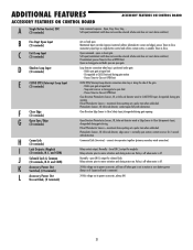
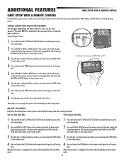
... FEATURES IMPORTANT SAFETY INFORMATION To prevent SERIOUS INJURY or DEATH from the gate. Have a qualified service person make repairs to gate hardware. • ALL maintenance MUST be performed by a LiftMaster professional. • Activate gate ONLY when it can be seen clearly, is properly adjusted and there... monthly. MAINTENANCE AND OPERATION • Locate entrapment protection devices to the operator or in BOTH the open and close gate cycles. The gate MUST reverse on a separate fused line of adequate capacity. • NEVER let children operate or play with fuse of...
... FEATURES IMPORTANT SAFETY INFORMATION To prevent SERIOUS INJURY or DEATH from the gate. Have a qualified service person make repairs to gate hardware. • ALL maintenance MUST be performed by a LiftMaster professional. • Activate gate ONLY when it can be seen clearly, is properly adjusted and there... monthly. MAINTENANCE AND OPERATION • Locate entrapment protection devices to the operator or in BOTH the open and close gate cycles. The gate MUST reverse on a separate fused line of adequate capacity. • NEVER let children operate or play with fuse of...
LA500 Manual
Page 10
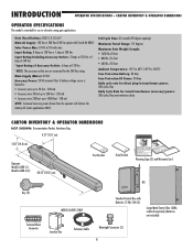
...Bag 4.21" (10.7 cm) 5.83" (14.8 cm) Operator Model LA500 (1) Model LA500-S (2) 40.35" (102.5 cm) Post Bracket Gate Bracket Warning Signs (2) and Warranty Card OR Key (2) Terminal Block Connector MODEL LA500-S ONLY Standard Control Box with Toroid Kit ONLY) Solar Power Max: 24 Vdc... ordered separately (batteries not included) Junction Box Extension Cable Watertight Connector (2) 8 Full Cycle Time: 32 seconds (90 degree opening) Maximum Travel Range: 115 degrees Maximum Gate Weight/Length: • 1600 lbs./8 foot • 800 lbs./16 foot • 600 lbs./18 foot Ambient Temperature:...
...Bag 4.21" (10.7 cm) 5.83" (14.8 cm) Operator Model LA500 (1) Model LA500-S (2) 40.35" (102.5 cm) Post Bracket Gate Bracket Warning Signs (2) and Warranty Card OR Key (2) Terminal Block Connector MODEL LA500-S ONLY Standard Control Box with Toroid Kit ONLY) Solar Power Max: 24 Vdc... ordered separately (batteries not included) Junction Box Extension Cable Watertight Connector (2) 8 Full Cycle Time: 32 seconds (90 degree opening) Maximum Travel Range: 115 degrees Maximum Gate Weight/Length: • 1600 lbs./8 foot • 800 lbs./16 foot • 600 lbs./18 foot Ambient Temperature:...
LA500 Manual
Page 11
...-in Loop Detector Connectors (Model LOOPDETLM Loop Detector) - Compatible with MyQ™ devices and Security✚ 2.0™ codes at close limit - OPEN LIMIT: ON at open limit switch - TAMPER: ON when gate manually pulled from the remote control • Wireless primary/secondary (refer to 50 remote controls and 2 keyless entries. CYCLE QUANTITY: LEDs...
...-in Loop Detector Connectors (Model LOOPDETLM Loop Detector) - Compatible with MyQ™ devices and Security✚ 2.0™ codes at close limit - OPEN LIMIT: ON at open limit switch - TAMPER: ON when gate manually pulled from the remote control • Wireless primary/secondary (refer to 50 remote controls and 2 keyless entries. CYCLE QUANTITY: LEDs...
LA500 Manual
Page 12
Suggested for more details). Although nothing can protect the gate operator in your gate application (refer to stay open when vehicles are obstructing the gate path. Check national and local codes for low and high voltage. Install warning signs on both sides of a direct lightning ...strike, proper grounding can absorb the tremendous power of the gate. ! ! Without this path, ...
Suggested for more details). Although nothing can protect the gate operator in your gate application (refer to stay open when vehicles are obstructing the gate path. Check national and local codes for low and high voltage. Install warning signs on both sides of a direct lightning ...strike, proper grounding can absorb the tremendous power of the gate. ! ! Without this path, ...
LA500 Manual
Page 13
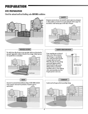
...Back Steel Bracket (Reinforce if necessary) Gate Hinge Gate Hinge NOTE: Weld Re Bar Behind Gate Hinges for Maximum Strength. PULL-TO-OPEN Column Install Post Install Gate Hinge Gate Hinge PUSH-TO-OPEN Column Install Gate Hinge SITE PREPARATION Post Install Gate Hinge Heavy Steel Plate for Reinforcement ...wires. The installation steps in this manual will show a typical Pull-to-Open application. Top View Heavy Steel Plate for Reinforcement (Not provided) Gate Hinge Control Box Operator SINGLE GATE ! Water Tight Conduit (Not provided) Earth Ground Rod Control Box Primary ...
...Back Steel Bracket (Reinforce if necessary) Gate Hinge Gate Hinge NOTE: Weld Re Bar Behind Gate Hinges for Maximum Strength. PULL-TO-OPEN Column Install Post Install Gate Hinge Gate Hinge PUSH-TO-OPEN Column Install Gate Hinge SITE PREPARATION Post Install Gate Hinge Heavy Steel Plate for Reinforcement ...wires. The installation steps in this manual will show a typical Pull-to-Open application. Top View Heavy Steel Plate for Reinforcement (Not provided) Gate Hinge Control Box Operator SINGLE GATE ! Water Tight Conduit (Not provided) Earth Ground Rod Control Box Primary ...
LA500 Manual
Page 15
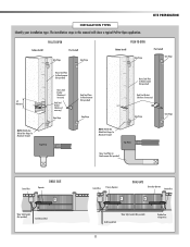
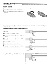
...Bracket Location 7.75" 8.5" If your application is Push-to-Open, refer to the illustration to page 15. PUSH-TO-OPEN 7.75" 8.5" 13 The operator is a replacement for the post bracket. 3 Place a measuring tape under the center of the gate hinge point and measure out 7.75 inches. 4 Use ... bracket in manual mode. DETERMINE THE POSITION OF THE POST BRACKET 1 Close the gate. 2 Choose a vertical mounting location for a Miracle-One™ operator, use the existing post bracket and gate bracket. INSTALLATION MANUAL RELEASE + DETERMINE THE POSITION OF THE POST BRACKET MANUAL RELEASE ...
...Bracket Location 7.75" 8.5" If your application is Push-to-Open, refer to the illustration to page 15. PUSH-TO-OPEN 7.75" 8.5" 13 The operator is a replacement for the post bracket. 3 Place a measuring tape under the center of the gate hinge point and measure out 7.75 inches. 4 Use ... bracket in manual mode. DETERMINE THE POSITION OF THE POST BRACKET 1 Close the gate. 2 Choose a vertical mounting location for a Miracle-One™ operator, use the existing post bracket and gate bracket. INSTALLATION MANUAL RELEASE + DETERMINE THE POSITION OF THE POST BRACKET MANUAL RELEASE ...
LA500 Manual
Page 27
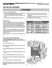
...the control board will automatically exit limit setting mode. ! Gate MUST reverse on which limit is being set . OFF NORMAL MODE Limits are not set . 7 Cycle the gate open and close limit. 4 Press and release the SET CLOSE or SET OPEN button depending on the control board (refer to Fine ...Tune the Force section) to the 1 position. ON LIMIT SETTING MODE Open limit is not set . SET OPEN LED BLINKING OFF BLINKING BLINKING ON...
...the control board will automatically exit limit setting mode. ! Gate MUST reverse on which limit is being set . OFF NORMAL MODE Limits are not set . 7 Cycle the gate open and close limit. 4 Press and release the SET CLOSE or SET OPEN button depending on the control board (refer to Fine ...Tune the Force section) to the 1 position. ON LIMIT SETTING MODE Open limit is not set . SET OPEN LED BLINKING OFF BLINKING BLINKING ON...
LA500 Manual
Page 32
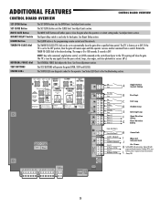
...CLOSE (TTC) dial can be set to OFF. The range is 0 to the TTC expiring will operate the gate (OPEN, STOP and CLOSE). C Exit Loop D Shadow Loop E Interrupt Loop F Open Direction Safety G Close Direction Safety H Comm Link I Mag and J Solenoid Lock Acc. The TTC is in... the Troubleshooting section. The TEST BUTTONS will close photoelectric sensors (IR's). OPEN CLOSE STOP SET OPEN SET CLOSE MOVE GATE OFF ON PRESS & RELEASE TO BEGIN LIMIT SETUP 1 2 (SECONDS) 10 5 60 XMITTER NETWORK STATUS: OFF INPUT POWER ...
...CLOSE (TTC) dial can be set to OFF. The range is 0 to the TTC expiring will operate the gate (OPEN, STOP and CLOSE). C Exit Loop D Shadow Loop E Interrupt Loop F Open Direction Safety G Close Direction Safety H Comm Link I Mag and J Solenoid Lock Acc. The TTC is in... the Troubleshooting section. The TEST BUTTONS will close photoelectric sensors (IR's). OPEN CLOSE STOP SET OPEN SET CLOSE MOVE GATE OFF ON PRESS & RELEASE TO BEGIN LIMIT SETUP 1 2 (SECONDS) 10 5 60 XMITTER NETWORK STATUS: OFF INPUT POWER ...
LA500 Manual
Page 33
...to Close Entrapments Input, disregarded during motor run . Disregarded at OPEN limit Close Direction Photoelectric Sensors, IR, or Infra-red detector wired to -Close at CLOSE limit and during gate opening Open Direction Photoelectric Sensors, IR, Infra-red detector wired or Edge ...Sensor to motor activation and during motor run . Pauses Timer-to CLOSE EYES Input, disregarded during gate motion - Soft open . Open, Stop, Close, Stop, ... Photoelectric ...
...to Close Entrapments Input, disregarded during motor run . Disregarded at OPEN limit Close Direction Photoelectric Sensors, IR, or Infra-red detector wired to -Close at CLOSE limit and during gate opening Open Direction Photoelectric Sensors, IR, Infra-red detector wired or Edge ...Sensor to motor activation and during motor run . Pauses Timer-to CLOSE EYES Input, disregarded during gate motion - Soft open . Open, Stop, Close, Stop, ... Photoelectric ...
LA500 Manual
Page 35
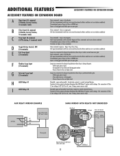
... Input (2 terminals) F Shadow Loop Input (2 terminals) G Interrupt Loop Input (2 terminals) H AUX Relay #1 I AUX Relay #2 Open command - opens a closed relay contacts to -Close at OPEN limit. opens a closed gate. Holds open - Stops and reverses a closing gate and holds open an open gate. Pauses Timer-to-Close at open (maintained switch does not override external safeties and does not reset alarm condition) If...
... Input (2 terminals) F Shadow Loop Input (2 terminals) G Interrupt Loop Input (2 terminals) H AUX Relay #1 I AUX Relay #2 Open command - opens a closed relay contacts to -Close at OPEN limit. opens a closed gate. Holds open - Stops and reverses a closing gate and holds open an open gate. Pauses Timer-to-Close at open (maintained switch does not override external safeties and does not reset alarm condition) If...
LA500 Manual
Page 36
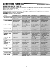
... alert signal (audible or visual alert system) Attach visual alert to ON for gate that delays upon opening 1) Use with SAMS (Sequence Access Management System) 2) Connect "Gate Open" indicator (e.g. Interrupt loop reverses a closing gate. If powered from battery and battery is low, gate stays close. not running on batteries) Attach alert signal (audible or visual alert...
... alert signal (audible or visual alert system) Attach visual alert to ON for gate that delays upon opening 1) Use with SAMS (Sequence Access Management System) 2) Connect "Gate Open" indicator (e.g. Interrupt loop reverses a closing gate. If powered from battery and battery is low, gate stays close. not running on batteries) Attach alert signal (audible or visual alert...
LA500 Manual
Page 37
... simultaneously to enter limit setting mode. 2 Press and hold the CLOSE button on the remote control until the gate reaches the desired open limit. This automatically sets the force. SET OPEN SET CLOSE B D FF SET OPEN SET CLOSE ER WO K MO E G TE STATUS R ES OB G LMT S C ND ) 10 2 5 OF N UT POW R TM R ...release the CLOSE button on the remote control again to set the close limit. 4 Press and release the OPEN button on the remote control again to set the open position. The gate MUST be jogged back and forth using a remote control, first you will exit the limit setting mode ...
... simultaneously to enter limit setting mode. 2 Press and hold the CLOSE button on the remote control until the gate reaches the desired open limit. This automatically sets the force. SET OPEN SET CLOSE B D FF SET OPEN SET CLOSE ER WO K MO E G TE STATUS R ES OB G LMT S C ND ) 10 2 5 OF N UT POW R TM R ...release the CLOSE button on the remote control again to set the close limit. 4 Press and release the OPEN button on the remote control again to set the open position. The gate MUST be jogged back and forth using a remote control, first you will exit the limit setting mode ...
LA500 Manual
Page 41
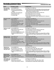
... Exit loop detector or loop wire d) Low battery with LOW BATT option set to close from gate and move easily and freely through its entire range, limit-to identify issue b) Check all Open inputs for an active input c) Check all Entrapment Protection Device inputs for an active sensor d) ...detector e) Check AC power and AC Fail option setting f) Check if AC power is available. Gate does not close e) Low battery with LOW BATT option set to CLOSE a) Timer-to-Close not set b) Open control active c) Close Entrapment Protection Device active d) Vehicle loop detector active e) Loss of AC...
... Exit loop detector or loop wire d) Low battery with LOW BATT option set to close from gate and move easily and freely through its entire range, limit-to identify issue b) Check all Open inputs for an active input c) Check all Entrapment Protection Device inputs for an active sensor d) ...detector e) Check AC power and AC Fail option setting f) Check if AC power is available. Gate does not close e) Low battery with LOW BATT option set to CLOSE a) Timer-to-Close not set b) Open control active c) Close Entrapment Protection Device active d) Vehicle loop detector active e) Loss of AC...
LA500 Manual
Page 42
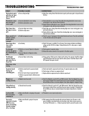
...power solenoid from control board accessory power terminals). TROUBLESHOOTING TROUBLESHOOTING CHART FAULT Obstruction in gate's path causes gate to stop, and may reverse direction. On dual-gate system, incorrect gate opens first or closes first. a) Main control board is wired to stop and ...reverse direction. Retest that activating edge sensor causes moving gate to stop or reverse gate. a) With expansion board disconnected and running...
...power solenoid from control board accessory power terminals). TROUBLESHOOTING TROUBLESHOOTING CHART FAULT Obstruction in gate's path causes gate to stop, and may reverse direction. On dual-gate system, incorrect gate opens first or closes first. a) Main control board is wired to stop and ...reverse direction. Retest that activating edge sensor causes moving gate to stop or reverse gate. a) With expansion board disconnected and running...


