
LA412DC Sell Sheet Manual
Page 2
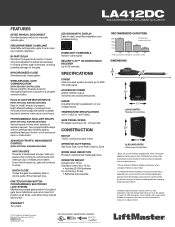
...power. TEMPERATURE SPECIFICATIONS -40º F (-40C) to manually operate gate. LiftMaster low power draw accessories recommended to 30W 12V solar panel. Inputs for dual-gate communication. OPERATOR WEIGHT Actuator Arm 19 lbs. Standard control box 13 lbs. • Includes (2) 7AH ... closes gates. QUICK CLOSE Closes the gate immediately after using manual disconnect. Does not include added accessory power draw. LA412DC SOLAR RESIDENTIAL DC LINEAR ACTUATOR FEATURES KEYED MANUAL DISCONNECT Provides simple method to 140ºF (60C) GATE TRAVEL SPEED 90...
...power. TEMPERATURE SPECIFICATIONS -40º F (-40C) to manually operate gate. LiftMaster low power draw accessories recommended to 30W 12V solar panel. Inputs for dual-gate communication. OPERATOR WEIGHT Actuator Arm 19 lbs. Standard control box 13 lbs. • Includes (2) 7AH ... closes gates. QUICK CLOSE Closes the gate immediately after using manual disconnect. Does not include added accessory power draw. LA412DC SOLAR RESIDENTIAL DC LINEAR ACTUATOR FEATURES KEYED MANUAL DISCONNECT Provides simple method to 140ºF (60C) GATE TRAVEL SPEED 90...
LA412DC Owner's Manual
Page 2
... WIRING 25 FINISH INSTALL 26 ADJUSTMENT 26 LIMIT AND FORCE ADJUSTMENT 26 OBSTRUCTION TEST 28 PROGRAMMING 29 REMOTE CONTROLS (NOT PROVIDED 29 LIFTMASTER INTERNET GATEWAY (NOT PROVIDED 30 ERASE ALL CODES 30 ERASE LIMITS 30 TO REMOVE AND ERASE MONITORED ENTRAPMENT PROTECTION DEVICES 30 OPERATION ... CHART 41 APPENDIX 44 BRACKET TYPES 44 LIMIT SETUP WITH A REMOTE CONTROL 45 REPAIR PARTS 46 CONTROL BOX 46 GATE OPERATOR ARM 46 WIRING DIAGRAM 47 STANDARD CONTROL BOX 47 LARGE METAL CONTROL BOX 48 ACCESSORIES 49 WARRANTY 50 TEMPLATE FOR POST BRACKET MOUNTING ...
... WIRING 25 FINISH INSTALL 26 ADJUSTMENT 26 LIMIT AND FORCE ADJUSTMENT 26 OBSTRUCTION TEST 28 PROGRAMMING 29 REMOTE CONTROLS (NOT PROVIDED 29 LIFTMASTER INTERNET GATEWAY (NOT PROVIDED 30 ERASE ALL CODES 30 ERASE LIMITS 30 TO REMOVE AND ERASE MONITORED ENTRAPMENT PROTECTION DEVICES 30 OPERATION ... CHART 41 APPENDIX 44 BRACKET TYPES 44 LIMIT SETUP WITH A REMOTE CONTROL 45 REPAIR PARTS 46 CONTROL BOX 46 GATE OPERATOR ARM 46 WIRING DIAGRAM 47 STANDARD CONTROL BOX 47 LARGE METAL CONTROL BOX 48 ACCESSORIES 49 WARRANTY 50 TEMPLATE FOR POST BRACKET MOUNTING ...

LA412DC Owner's Manual
Page 4
.... 10. One or more contact sensors shall be located at any location in contact with the vehicular gate during the entire path of a vertical barrier (arm). 3 c. One or more contact sensors shall be incorporated into public access areas. 7. SAFETY SAFETY INSTALLATION INFORMATION 1. Vehicular gate systems provide convenience and security. The gate...
.... 10. One or more contact sensors shall be located at any location in contact with the vehicular gate during the entire path of a vertical barrier (arm). 3 c. One or more contact sensors shall be incorporated into public access areas. 7. SAFETY SAFETY INSTALLATION INFORMATION 1. Vehicular gate systems provide convenience and security. The gate...

LA412DC Owner's Manual
Page 13
... screwdriver or dowel rod. 5. Temporarily secure gate post bracket with washer, lock washer and nut. Temporarily secure the gate bracket using a clamp. 4. The gate operator (arm) must be mounted several places on gate for reference. Manually open and close the gate. 2. Open the gate to -open bracket and post bracket and...
... screwdriver or dowel rod. 5. Temporarily secure gate post bracket with washer, lock washer and nut. Temporarily secure the gate bracket using a clamp. 4. The gate operator (arm) must be mounted several places on gate for reference. Manually open and close the gate. 2. Open the gate to -open bracket and post bracket and...

LA412DC Owner's Manual
Page 14
GATE BRACKET The gate operator (arm) must be level. 1. Secure the post bracket to verify that are large enough for the post bracket. Welder (Optional) Hex Nuts Lock Washers Flat Washers ... Bar OR OR Wood Angle Iron 13 Remove the clamp and the operator, set aside. 2. INSTALLATION STEP 4 SECURE THE BRACKETS POST BRACKET The gate operator (arm) must be level. Manually move the gate to the gate post using hardware (not provided). 3. Drill adequate holes in gate (or reinforcement, if necessary) that...
GATE BRACKET The gate operator (arm) must be level. 1. Secure the post bracket to verify that are large enough for the post bracket. Welder (Optional) Hex Nuts Lock Washers Flat Washers ... Bar OR OR Wood Angle Iron 13 Remove the clamp and the operator, set aside. 2. INSTALLATION STEP 4 SECURE THE BRACKETS POST BRACKET The gate operator (arm) must be level. Manually move the gate to the gate post using hardware (not provided). 3. Drill adequate holes in gate (or reinforcement, if necessary) that...

LA412DC Owner's Manual
Page 17
... switch. STEP 6 EARTH GROUND ROD Use the proper earth ground rod for proper depth Earth Ground Rod (Within 3' (0.9 m) of control box) STEP 7 WIRE THE OPERATOR ARM TO THE CONTROL BOARD 1. Install the earth ground rod within 3 feet of wire. Run wire from the control board with national and local electrical codes...
... switch. STEP 6 EARTH GROUND ROD Use the proper earth ground rod for proper depth Earth Ground Rod (Within 3' (0.9 m) of control box) STEP 7 WIRE THE OPERATOR ARM TO THE CONTROL BOARD 1. Install the earth ground rod within 3 feet of wire. Run wire from the control board with national and local electrical codes...

LA412DC Owner's Manual
Page 18
... the LEARN button again on the primary control board. OPEN CLOSE STOP WIRELESS DUAL GATES INSTALL A SECOND OPERATOR ARM AND CONTROL BOX Install a second operator arm and control box by following installation steps 1-7. The yellow NETWORK LED will light. 6. Press and release the ...) then turn off indicating successful deactivation. The yellow NETWORK LED will blink (operator will light. 7. Repeat the steps for each operator arm. Do not use wired and wireless communication simultaneously. The green XMITTER LED will light. 3. The yellow NETWORK LED will light. 2. ...
... the LEARN button again on the primary control board. OPEN CLOSE STOP WIRELESS DUAL GATES INSTALL A SECOND OPERATOR ARM AND CONTROL BOX Install a second operator arm and control box by following installation steps 1-7. The yellow NETWORK LED will light. 6. Press and release the ...) then turn off indicating successful deactivation. The yellow NETWORK LED will blink (operator will light. 7. Repeat the steps for each operator arm. Do not use wired and wireless communication simultaneously. The green XMITTER LED will light. 3. The yellow NETWORK LED will light. 2. ...

LA412DC Owner's Manual
Page 19
Use PVC conduit to prevent damage to be used for the watertight connectors. 4. DUAL GATES ONLY WIRED DUAL GATES INSTALL A SECOND OPERATOR ARM Install a second operator arm by tightening the connector nut. 11. Connect the wires from operator cable. Remove terminals from extension cable to bury the extension cable. Put wires inside ...
Use PVC conduit to prevent damage to be used for the watertight connectors. 4. DUAL GATES ONLY WIRED DUAL GATES INSTALL A SECOND OPERATOR ARM Install a second operator arm by tightening the connector nut. 11. Connect the wires from operator cable. Remove terminals from extension cable to bury the extension cable. Put wires inside ...
LA412DC Owner's Manual
Page 20
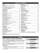
... other . Primary Gate OUTSIDE PROPERTY SET THE BIPART DELAY (DUAL CONTROL BOX) Primary Gate - DUAL GATES ONLY WIRED DUAL GATES INSTALLATION WIRE THE SECONDARY OPERATOR ARM TO THE CONTROL BOARD 1. This would require one gate will delay from the close limit when opening and be set the LOCK/BIPART DELAY switch...
... other . Primary Gate OUTSIDE PROPERTY SET THE BIPART DELAY (DUAL CONTROL BOX) Primary Gate - DUAL GATES ONLY WIRED DUAL GATES INSTALLATION WIRE THE SECONDARY OPERATOR ARM TO THE CONTROL BOARD 1. This would require one gate will delay from the close limit when opening and be set the LOCK/BIPART DELAY switch...

LA412DC Owner's Manual
Page 34
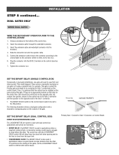
... (RPM/current sensor) detects the following (twice consecutively) the alarm will sound (up to 5 minutes) and the operator will need to be reset. The operator arm or gate is low. B. C Remove any obstructions. If the remote control is activated while the gate is moving A freely. The operator alarm will beep 3 times...
... (RPM/current sensor) detects the following (twice consecutively) the alarm will sound (up to 5 minutes) and the operator will need to be reset. The operator arm or gate is low. B. C Remove any obstructions. If the remote control is activated while the gate is moving A freely. The operator alarm will beep 3 times...

LA412DC Owner's Manual
Page 39
.... Linear Drive Disengaged (Arm 1) Disengage then re-engage arm, check wiring and connections. Operator may be at end of monitored entrapment protection devices (one) not installed. Make sure you do NOT have a 12V battery on main board; Loop Error - LiftMaster Plug-in Loop Detector ...only) Check loop wiring throughout connection. May be a short in the loop, or an open connection in the loop. Rarely, may be standard operation. Pass-point not detected (Arm 2) Check yellow pass-point wiring....
.... Linear Drive Disengaged (Arm 1) Disengage then re-engage arm, check wiring and connections. Operator may be at end of monitored entrapment protection devices (one) not installed. Make sure you do NOT have a 12V battery on main board; Loop Error - LiftMaster Plug-in Loop Detector ...only) Check loop wiring throughout connection. May be a short in the loop, or an open connection in the loop. Rarely, may be standard operation. Pass-point not detected (Arm 2) Check yellow pass-point wiring....

LA412DC Owner's Manual
Page 40
... (secondary control box) 81 Open input (EYE/EDGE) communication fault (secondary control box) Force reversal (Arm 1) 91 Force reversal (Arm 2) 92 RPM / STALL Reversal (Arm 1) 93 RPM / STALL Reversal (Arm 2) 94 99 Normal Operation Solution Check wired input for obstruction. If an obstruction did NOT occur, check...and Obstruction Test. If an obstruction did NOT occur, check alignment, inputs, and wiring. If no obstruction, check that the operator arm is engaged and free to move . If no action required. IF an obstruction occurred, no action required. Refer to Limit and ...
... (secondary control box) 81 Open input (EYE/EDGE) communication fault (secondary control box) Force reversal (Arm 1) 91 Force reversal (Arm 2) 92 RPM / STALL Reversal (Arm 1) 93 RPM / STALL Reversal (Arm 2) 94 99 Normal Operation Solution Check wired input for obstruction. If an obstruction did NOT occur, check...and Obstruction Test. If an obstruction did NOT occur, check alignment, inputs, and wiring. If no obstruction, check that the operator arm is engaged and free to move . If no action required. IF an obstruction occurred, no action required. Refer to Limit and ...
LA412DC Owner's Manual
Page 42
... power, then running on . Charge batteries by AC or solar power or replace batteries Gate opens, but will not close when setting limits. Arm moves, but motor does not run and error code display not on batteries and battery voltage must be 11.5 Vdc or higher. a) Open... control active b) Vehicle loop detector active c) Loss of operator. Correct as necessary. Repair gate as needed . c) Remove arm from gate and move easily and freely through its entire range, limit-to the gate post. e) Check Fire Dept input f) Check Timer-to a wireless ...
... power, then running on . Charge batteries by AC or solar power or replace batteries Gate opens, but will not close when setting limits. Arm moves, but motor does not run and error code display not on batteries and battery voltage must be 11.5 Vdc or higher. a) Open... control active b) Vehicle loop detector active c) Loss of operator. Correct as necessary. Repair gate as needed . c) Remove arm from gate and move easily and freely through its entire range, limit-to the gate post. e) Check Fire Dept input f) Check Timer-to a wireless ...

LA412DC Owner's Manual
Page 47
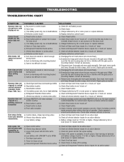
...-36806-3 K94-36891 K77-36541 LA412CONTDC Metal Control Box Only J15 Harness Antenna Standard Plastic Control Box (with control board) 4 2 6 3 5 7 3 GATE OPERATOR ARM ITEM PART NUMBER 1 LA412 DESCRIPTION Primary Arm 2 41ASWG-442SA Release Lever 3 41ASWG-0594SA Motor with Limit Switch Harness 4 41ASWG-0014SA Rear Connector 4 25 41ASWG-0597SA Cable 12 V with Connector...
...-36806-3 K94-36891 K77-36541 LA412CONTDC Metal Control Box Only J15 Harness Antenna Standard Plastic Control Box (with control board) 4 2 6 3 5 7 3 GATE OPERATOR ARM ITEM PART NUMBER 1 LA412 DESCRIPTION Primary Arm 2 41ASWG-442SA Release Lever 3 41ASWG-0594SA Motor with Limit Switch Harness 4 41ASWG-0014SA Rear Connector 4 25 41ASWG-0597SA Cable 12 V with Connector...


