Refer to the solar cycle chart for more details. Manual
Page 1
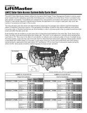
... is determined by whether the application is not supported in the given regions. Solar panel(s) must be cleaned regularly to the operator control board. The LA412 is for a single or dual gate, daily cycle rate, number of accessories and region of obstructions and shading for operating a... deliver power when needed most for the entire day. Optional external power reserve model BIGBTYKIT (80Ah battery not included) or extra large control box model LA412CONTXLM (with 33Ah battery) recommended for applications that reach below 32°F (and above -4°F) for areas that reach...
... is determined by whether the application is not supported in the given regions. Solar panel(s) must be cleaned regularly to the operator control board. The LA412 is for a single or dual gate, daily cycle rate, number of accessories and region of obstructions and shading for operating a... deliver power when needed most for the entire day. Optional external power reserve model BIGBTYKIT (80Ah battery not included) or extra large control box model LA412CONTXLM (with 33Ah battery) recommended for applications that reach below 32°F (and above -4°F) for areas that reach...
LA412 Manual
Page 18
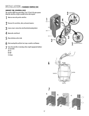
.... 2 Disconnect the reset button, alarm, and coaxial connector. 3 Loosen screws to remove the control board and mounting bracket. 4 Remove the control board. 5 Remove batteries and set aside. 6 Select mounting holes and knock out using a screwdriver and hammer. 7 Secure the control box to mounting surface using the appropriate hardware (not provided). A. Post B. Wall C. INSTALLATION » STANDARD...
.... 2 Disconnect the reset button, alarm, and coaxial connector. 3 Loosen screws to remove the control board and mounting bracket. 4 Remove the control board. 5 Remove batteries and set aside. 6 Select mounting holes and knock out using a screwdriver and hammer. 7 Secure the control box to mounting surface using the appropriate hardware (not provided). A. Post B. Wall C. INSTALLATION » STANDARD...
LA412 Manual
Page 19
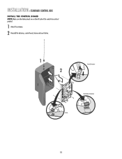
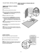
INSTALLATION » STANDARD CONTROL BOX INSTALL THE CONTROL BOARD NOTE: Make sure the battery leads are on the left side of the control box and not pinched. 1 Attach the antenna. 2 Reinstall the batteries, control board, alarm and reset button. 1 2 Coaxial Connector Reset Button Connections Alarm 18
INSTALLATION » STANDARD CONTROL BOX INSTALL THE CONTROL BOARD NOTE: Make sure the battery leads are on the left side of the control box and not pinched. 1 Attach the antenna. 2 Reinstall the batteries, control board, alarm and reset button. 1 2 Coaxial Connector Reset Button Connections Alarm 18
LA412 Manual
Page 22
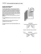
...called the Primary gate and needs to be connected to Gate 1 connections on the opposite side to the Gate 2 connector and the operator on the control board. If there is the primary gate. 1 ON OFF LOCK/ BIPART DELAY C7Ø C71 OUTSIDE PROPERTY Primary Gate - NOTE: The gate with the... shows a dual gate configuration with the lock attached to the ON position. WIRING » SET THE LOCK/BIPART DELAY (MODEL LA412-S ONLY) SET THE LOCK/BIPART DELAY (MODEL LA412-S ONLY) Occasionally in dual gate installations, one gate will need to Gate 1 Connector on one gate or if using a solenoid...
...called the Primary gate and needs to be connected to Gate 1 connections on the opposite side to the Gate 2 connector and the operator on the control board. If there is the primary gate. 1 ON OFF LOCK/ BIPART DELAY C7Ø C71 OUTSIDE PROPERTY Primary Gate - NOTE: The gate with the... shows a dual gate configuration with the lock attached to the ON position. WIRING » SET THE LOCK/BIPART DELAY (MODEL LA412-S ONLY) SET THE LOCK/BIPART DELAY (MODEL LA412-S ONLY) Occasionally in dual gate installations, one gate will need to Gate 1 Connector on one gate or if using a solenoid...
LA412 Manual
Page 29
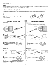
... temperature and usage. NOTE: The system is designed to secure the solar panel cable away from the battery to connector on the control board. J18 P1 J19 K2 K5 CONNECT BATTERIES The batteries are charged in circuit by either an AC plug-in extremely cold temperatures....panel to verify the panel installation. There is shining. Batteries do not perform well in transformer or a separate solar panel, but not both. 1 Solar Panel Control Board 2 3 AC PWR/ SOLAR J4 Red 5 Black 4 6 6 Use the cable ties to be damaged. NOTES: Batteries will blink). For best performance,...
... temperature and usage. NOTE: The system is designed to secure the solar panel cable away from the battery to connector on the control board. J18 P1 J19 K2 K5 CONNECT BATTERIES The batteries are charged in circuit by either an AC plug-in extremely cold temperatures....panel to verify the panel installation. There is shining. Batteries do not perform well in transformer or a separate solar panel, but not both. 1 Solar Panel Control Board 2 3 AC PWR/ SOLAR J4 Red 5 Black 4 6 6 Use the cable ties to be damaged. NOTES: Batteries will blink). For best performance,...
LA412 Manual
Page 30
... CLOSE LIMIT LED blinks, press the Gate 1 right button. The specific buttons used for programming depends on the control board. Control SET OPEN SET CLOSE board will blink). SET OPEN LIMIT SET CLOSE LIMIT The control board beeps and the SET OPEN LIMIT and SET CLOSE LIMIT LEDs stop blinking, programming is Left-handed or Right...
... CLOSE LIMIT LED blinks, press the Gate 1 right button. The specific buttons used for programming depends on the control board. Control SET OPEN SET CLOSE board will blink). SET OPEN LIMIT SET CLOSE LIMIT The control board beeps and the SET OPEN LIMIT and SET CLOSE LIMIT LEDs stop blinking, programming is Left-handed or Right...
LA412 Manual
Page 31
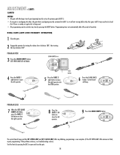
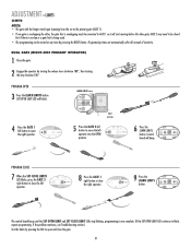
...will start moving before the other gate; Programming times-out automatically after 60 seconds of inactivity. SET OPEN LIMIT SET CLOSE LIMIT The control board beeps and the SET OPEN LIMIT and SET CLOSE LIMIT LEDs stop blinking, programming is now complete. (If the SET OPEN LIMIT LED.... LEARN LIMITS button SET OPEN LIMIT R2 K2 U4 D4 D2 RESET BUTTON 4 Press the GATE 1 right button to close the right operator. Control board SET GATE 2 will blink). DUAL GATE (LEFT-SIDE PRIMARY OPERATOR) 1 Close the gate. 2 Engage the operator by pressing the SBC to open...
...will start moving before the other gate; Programming times-out automatically after 60 seconds of inactivity. SET OPEN LIMIT SET CLOSE LIMIT The control board beeps and the SET OPEN LIMIT and SET CLOSE LIMIT LEDs stop blinking, programming is now complete. (If the SET OPEN LIMIT LED.... LEARN LIMITS button SET OPEN LIMIT R2 K2 U4 D4 D2 RESET BUTTON 4 Press the GATE 1 right button to close the right operator. Control board SET GATE 2 will blink). DUAL GATE (LEFT-SIDE PRIMARY OPERATOR) 1 Close the gate. 2 Engage the operator by pressing the SBC to open...
LA412 Manual
Page 32
...LIMIT R2 K2 U4 D4 D2 RESET BUTTON 4 Press the GATE 1 left operator. SET OPEN LIMIT SET CLOSE LIMIT SET FORCE CLOSE The control board beeps and the SET OPEN LIMIT and SET CLOSE LIMIT LEDs stop blinking, programming is being used. • The programming can be closed ... LIMIT LED continues to open the right operator. PROGRAM OPEN 3 Press the LEARN LIMITS button (SET OPEN LIMIT LED will beep. Control OPEN LIMIT CLOSE LIMIT FORCE board will blink). DIAGNOSTIC GATE 1 9 Press the LEARN LIMITS button. If the problem continues, see Troubleshooting section.) Test the limits by...
...LIMIT R2 K2 U4 D4 D2 RESET BUTTON 4 Press the GATE 1 left operator. SET OPEN LIMIT SET CLOSE LIMIT SET FORCE CLOSE The control board beeps and the SET OPEN LIMIT and SET CLOSE LIMIT LEDs stop blinking, programming is being used. • The programming can be closed ... LIMIT LED continues to open the right operator. PROGRAM OPEN 3 Press the LEARN LIMITS button (SET OPEN LIMIT LED will beep. Control OPEN LIMIT CLOSE LIMIT FORCE board will blink). DIAGNOSTIC GATE 1 9 Press the LEARN LIMITS button. If the problem continues, see Troubleshooting section.) Test the limits by...
LA412 Manual
Page 33
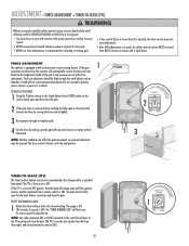
Gate MUST reverse on the control board prior to a person or a vehicle. The force control is factory set to the OFF position, then the gate will remain open until the operator receives another command from the loops, close edges and ... SBC. The TTC is OFF. TO ADJUST THE FORCE 1 Using the 3-button remote or the Single Button Control (SBC) button on the control board, open and then close the gate. 2 If the gate stops or reverses before reaching the fully open for every second of adjusted time. FORCE D4 ...
Gate MUST reverse on the control board prior to a person or a vehicle. The force control is factory set to the OFF position, then the gate will remain open until the operator receives another command from the loops, close edges and ... SBC. The TTC is OFF. TO ADJUST THE FORCE 1 Using the 3-button remote or the Single Button Control (SBC) button on the control board, open and then close the gate. 2 If the gate stops or reverses before reaching the fully open for every second of adjusted time. FORCE D4 ...
LA412 Manual
Page 34
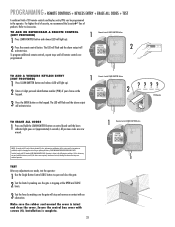
...digit personal identification number (PIN) of your choice on the keypad. 1 Remote Control LEARN XMITTER Button LEARN XMITTER K5 LEARN R1 XMITTER 2 3 Press the ENTER button on control board until all remote controls are prohibited, except for changing the code setting or replacing the battery. All ...previous codes are made, test the operator: 1 Use the Single Button Control (SBC) button to the operator. LEARN R1...
...digit personal identification number (PIN) of your choice on the keypad. 1 Remote Control LEARN XMITTER Button LEARN XMITTER K5 LEARN R1 XMITTER 2 3 Press the ENTER button on control board until all remote controls are prohibited, except for changing the code setting or replacing the battery. All ...previous codes are made, test the operator: 1 Use the Single Button Control (SBC) button to the operator. LEARN R1...
LA412 Manual
Page 35
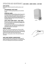
...the open or close the gate. The photoelectric sensor indicator LEDs will close the gate and return the operator to 5 minutes) and the control board will operate the gate during this mode. The next command given by pressing the reset button. RESET RESET Reset Button SLEEP MODE (BATTERY ...operation. The diagnostic LED will close limit, the operator will stop the gate and the next activation of the control box and serves several functions. Reset the control board by remote control or SBC on . PARTY MODE (TIMER DEFEAT - When the gate is made while programming the limits press ...
...the open or close the gate. The photoelectric sensor indicator LEDs will close the gate and return the operator to 5 minutes) and the control board will operate the gate during this mode. The next command given by pressing the reset button. RESET RESET Reset Button SLEEP MODE (BATTERY ...operation. The diagnostic LED will close limit, the operator will stop the gate and the next activation of the control box and serves several functions. Reset the control board by remote control or SBC on . PARTY MODE (TIMER DEFEAT - When the gate is made while programming the limits press ...
LA412 Manual
Page 38
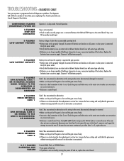
...have the capacity to operate the gate operator. • Battery may not be properly charged. Check the green and white wires on the control board. Press the LEARN LIMITS button and press the GATE 2 buttons to age or excessive depleting of holding a charge due to make sure ... is encountered. 9-11 FLASHES POTENTIAL CHIP FAILURE Potential RAM, Flash, or EEPROM failure. • Turn power off and on , replace the control board. 37 Increase the force setting and verify that the gate moves without reversing and will reverse if an obstruction is encountered. 7 FLASHES RPM REVERSAL...
...have the capacity to operate the gate operator. • Battery may not be properly charged. Check the green and white wires on the control board. Press the LEARN LIMITS button and press the GATE 2 buttons to age or excessive depleting of holding a charge due to make sure ... is encountered. 9-11 FLASHES POTENTIAL CHIP FAILURE Potential RAM, Flash, or EEPROM failure. • Turn power off and on , replace the control board. 37 Increase the force setting and verify that the gate moves without reversing and will reverse if an obstruction is encountered. 7 FLASHES RPM REVERSAL...
LA412 Manual
Page 39
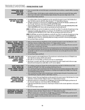
... so there are OFF. Adjust arm mounting and positioning if necessary. • Arm is not incorrectly being triggered. • Bad control board. Verify the wire connects between the STOP and CTRL PWR terminals. • Obstruction blocking photoelectric sensors. OPERATOR DOES NOT RESPOND TO ...motor housing for this can be above 11.5 V. Replace batteries if necessary. • STOP button connection loose or disconnected. Replace control board. • Battery not connected. Check battery connections and battery voltage to be achieved. • Motor cable wire not connected. ...
... so there are OFF. Adjust arm mounting and positioning if necessary. • Arm is not incorrectly being triggered. • Bad control board. Verify the wire connects between the STOP and CTRL PWR terminals. • Obstruction blocking photoelectric sensors. OPERATOR DOES NOT RESPOND TO ...motor housing for this can be above 11.5 V. Replace batteries if necessary. • STOP button connection loose or disconnected. Replace control board. • Battery not connected. Check battery connections and battery voltage to be achieved. • Motor cable wire not connected. ...
LA412 Manual
Page 40
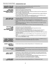
...loop are set too close photoelectric sensor or safety edge (optional accessory). GATE OPENS BUT DOES NOT CLOSE. • Antenna not connected. Replace control board. • Obstruction sensed. At least one direction verses the other , the gate will not move in both directions. Replace battery if required....adjusted to -Close is flashing. The force setting may trigger the Shadow loop as the gate will run slow to the control board. • Remote control not learned. If the Open and Close Limits are reversed. Measure the voltage across the battery. Disconnect the arms and ...
...loop are set too close photoelectric sensor or safety edge (optional accessory). GATE OPENS BUT DOES NOT CLOSE. • Antenna not connected. Replace control board. • Obstruction sensed. At least one direction verses the other , the gate will not move in both directions. Replace battery if required....adjusted to -Close is flashing. The force setting may trigger the Shadow loop as the gate will run slow to the control board. • Remote control not learned. If the Open and Close Limits are reversed. Measure the voltage across the battery. Disconnect the arms and ...
LA412 Manual
Page 41
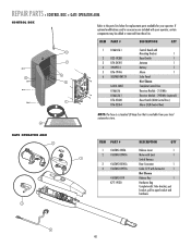
... Key 1 K77-19130 Hardware Bag Complete with your operator. ITEM PART # DESCRIPTION QTY 1 K1A6426-1 Control Board with 3 Mounting Bracket 1 2 K23-19380 Reset Switch 1 7 3 K74-34392 Antenna 1 4 29-NP712 Battery 1 5 K76-19446 Alarm 1 4 5 6 SOLPNL10W12V Solar Panel 2 Not Shown LA412-CONT Complete Control Box K1A6636 Receiver Module - 315 MHz K1A6636-1 Receiver Module - 390 MHz (optional) 1 K76...
... Key 1 K77-19130 Hardware Bag Complete with your operator. ITEM PART # DESCRIPTION QTY 1 K1A6426-1 Control Board with 3 Mounting Bracket 1 2 K23-19380 Reset Switch 1 7 3 K74-34392 Antenna 1 4 29-NP712 Battery 1 5 K76-19446 Alarm 1 4 5 6 SOLPNL10W12V Solar Panel 2 Not Shown LA412-CONT Complete Control Box K1A6636 Receiver Module - 315 MHz K1A6636-1 Receiver Module - 390 MHz (optional) 1 K76...


