HS670 GL BOARD Manual
Page 5
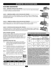
...reverse of the gate within the operator. Type B2: Connections provided for use in audio alarm (e.g., sirens, horns or buzzers). A contact device such as a gate edge can be ... of entrapment protection. CLASS III - SAFETY ACCESSORY SELECTION All UL325 compliant LiftMaster gate operators will accept external entrapment protection devices to protect people from motorized... access is for use separate entrance MODEL CLASS 1 CLASS 2 CLASS 3 CLASS 4 HS670 GC HS670 GI N/A N/A UL325 ENTRAPMENT PROTECTION REQUIREMENTS GATE OPERATOR ENTRAPMENT PROTECTION UL325 Installation Class Class ...
...reverse of the gate within the operator. Type B2: Connections provided for use in audio alarm (e.g., sirens, horns or buzzers). A contact device such as a gate edge can be ... of entrapment protection. CLASS III - SAFETY ACCESSORY SELECTION All UL325 compliant LiftMaster gate operators will accept external entrapment protection devices to protect people from motorized... access is for use separate entrance MODEL CLASS 1 CLASS 2 CLASS 3 CLASS 4 HS670 GC HS670 GI N/A N/A UL325 ENTRAPMENT PROTECTION REQUIREMENTS GATE OPERATOR ENTRAPMENT PROTECTION UL325 Installation Class Class ...

HS670 GL BOARD Manual
Page 15
..., open or override open limit the timer to the close limit when the edge is detected (gate edge or RPM sensor), gate will stop and alarm. WARN MAG EDGE OPEN S2 ON ON 1 2 34 GL Controller Board Force Control Max. Obstruction While Opening (Edge/Photo Eye Input) 5 6 7 8 9 10 ...reverse a closing gate to close. On most operators this input when the gate is detected (gate edge or RPM sensor), gate will stop and alarm. Photo Eye Input: See Programming Section on page 18. Once the input is configured for the gate opening gate. PHOTO CLOSE S2 Close Photo ...
..., open or override open limit the timer to the close limit when the edge is detected (gate edge or RPM sensor), gate will stop and alarm. WARN MAG EDGE OPEN S2 ON ON 1 2 34 GL Controller Board Force Control Max. Obstruction While Opening (Edge/Photo Eye Input) 5 6 7 8 9 10 ...reverse a closing gate to close. On most operators this input when the gate is detected (gate edge or RPM sensor), gate will stop and alarm. Photo Eye Input: See Programming Section on page 18. Once the input is configured for the gate opening gate. PHOTO CLOSE S2 Close Photo ...
HS670 GL BOARD Manual
Page 17
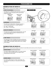
... opening direction, to the left or to the off position. "SAVE" SWITCH This switch (S1-4) stores all settings into memory and locks out changes. The alarm will be a half second delay after the maglock relay is determined from the inside of fence looking out. TIMER TO CLOSE ENABLED TIMER TO CLOSE... TIMER TO CLOSE Max = 180 sec Min = 0 sec LT SL LT SL SLIDE/SWING This switch (S1-2) selects slide or swing gate operation, in motion" alarm feature. MAG WARN MAGLOCK ENABLED S2 ON ON 1 2 34 OPED CLED WARN MAG MAGLOCK DISABLED S2 ON ON 1 2 34 OPED CLED PH PH PH PH...
... opening direction, to the left or to the off position. "SAVE" SWITCH This switch (S1-4) stores all settings into memory and locks out changes. The alarm will be a half second delay after the maglock relay is determined from the inside of fence looking out. TIMER TO CLOSE ENABLED TIMER TO CLOSE... TIMER TO CLOSE Max = 180 sec Min = 0 sec LT SL LT SL SLIDE/SWING This switch (S1-2) selects slide or swing gate operation, in motion" alarm feature. MAG WARN MAGLOCK ENABLED S2 ON ON 1 2 34 OPED CLED WARN MAG MAGLOCK DISABLED S2 ON ON 1 2 34 OPED CLED PH PH PH PH...

HS670 GL BOARD Manual
Page 21
.../RESET AUXILIARY CONTROL WIRING Terminals 6 & 5 (Com) - Interrupt (Safety) Loop Input These terminals are applied to the open the gate by the gate stopped and entrapment alarm on swing gate operators. Terminals 2 & 5 (Com) - Stop/Reset Control Input Single Button Input 21 Activation of this input for use only with a radio receiver in...
.../RESET AUXILIARY CONTROL WIRING Terminals 6 & 5 (Com) - Interrupt (Safety) Loop Input These terminals are applied to the open the gate by the gate stopped and entrapment alarm on swing gate operators. Terminals 2 & 5 (Com) - Stop/Reset Control Input Single Button Input 21 Activation of this input for use only with a radio receiver in...

HS670 GL BOARD Manual
Page 24
... of problem Completion of communications between the different diagnostic codes. LED LED NAME DESCRIPTION D6 Contactor A D5 Contactor B D4 SAM D3 Lock D2 Alarm On when Contactor A is activated On when Contactor B is activated On when SAM relay is activated On when Mag Lock relay is activated On... when Alarm Relay is on in an 8 second period. The LEDs are illuminated when the limit switch contacts are 5 troubleshooting LEDs on for the open ...
... of problem Completion of communications between the different diagnostic codes. LED LED NAME DESCRIPTION D6 Contactor A D5 Contactor B D4 SAM D3 Lock D2 Alarm On when Contactor A is activated On when Contactor B is activated On when SAM relay is activated On when Mag Lock relay is activated On... when Alarm Relay is on in an 8 second period. The LEDs are illuminated when the limit switch contacts are 5 troubleshooting LEDs on for the open ...

HS670 GL BOARD Manual
Page 26
... accessory may be set off , make sure factory plug-in the same conduit with any two power leads at normal operating speed. OPERATOR STOPS AND ALARMS 1) Operator's manual release is engaged. 2) Operator's main power is not engaged. RADIO CONTROLS WILL NOT CLOSE THE GATE FROM THE OPEN LIMIT 1) Radio terminals R1...
... accessory may be set off , make sure factory plug-in the same conduit with any two power leads at normal operating speed. OPERATOR STOPS AND ALARMS 1) Operator's manual release is engaged. 2) Operator's main power is not engaged. RADIO CONTROLS WILL NOT CLOSE THE GATE FROM THE OPEN LIMIT 1) Radio terminals R1...

HS670 GL BOARD Manual
Page 30
Transformer primary voltage same as line voltage. 4. (B+) and (B-) are 100dB safety alarms. 5. Wire color: 120V black, 230V orange. 3. For single button radio function, perform optional wire change. 30 Coil voltage same as operator line voltage 24V secondary 60VA. 2. 01-G10028-1 SINGLE PHASE WIRING DIAGRAM EMMERSON MOTOR CONNECTIONS OVERLOAD (SEE NOTE 6) BALDOR MOTOR CONNECTIONS (LEFT) (RIGHT) NOTES: 1.
Transformer primary voltage same as line voltage. 4. (B+) and (B-) are 100dB safety alarms. 5. Wire color: 120V black, 230V orange. 3. For single button radio function, perform optional wire change. 30 Coil voltage same as operator line voltage 24V secondary 60VA. 2. 01-G10028-1 SINGLE PHASE WIRING DIAGRAM EMMERSON MOTOR CONNECTIONS OVERLOAD (SEE NOTE 6) BALDOR MOTOR CONNECTIONS (LEFT) (RIGHT) NOTES: 1.

HS670 GL BOARD Manual
Page 31
For single button radio function, perform the optional wire change. 31 01-G10028-3 THREE PHASE WIRING DIAGRAM 4 (LEFT) (RIGHT) NOTES: 1. Wire color: 230V orange, 460V violet. 3. Transformer primary voltage same as line voltage. 4. (B+) and (B-) are 100dB safety alarms. 5. Coil voltage same as operator line voltage 24V secondary 60VA. 2.
For single button radio function, perform the optional wire change. 31 01-G10028-3 THREE PHASE WIRING DIAGRAM 4 (LEFT) (RIGHT) NOTES: 1. Wire color: 230V orange, 460V violet. 3. Transformer primary voltage same as line voltage. 4. (B+) and (B-) are 100dB safety alarms. 5. Coil voltage same as operator line voltage 24V secondary 60VA. 2.

