
GT- Logic 4 Installation Manual
Page 2
... the Photoelectric Sensors (Provided 22 Wire the LiftMaster Monitored Entrapment Protection (LMEP) Devices 22 ADJUSTMENT 23-24 Limit Adjustment 23 Clutch Adjustment (Belt Drive Model Operators 24 TESTING 25 MANUAL RELEASE 26-27 Emergency Disconnect System Model GT and T 26 Emergency Disconnect System Model APT 26 Emergency Disconnect System Model H, GH, J, and HJ 27 PROGRAMMING 28...
... the Photoelectric Sensors (Provided 22 Wire the LiftMaster Monitored Entrapment Protection (LMEP) Devices 22 ADJUSTMENT 23-24 Limit Adjustment 23 Clutch Adjustment (Belt Drive Model Operators 24 TESTING 25 MANUAL RELEASE 26-27 Emergency Disconnect System Model GT and T 26 Emergency Disconnect System Model APT 26 Emergency Disconnect System Model H, GH, J, and HJ 27 PROGRAMMING 28...

GT- Logic 4 Installation Manual
Page 4
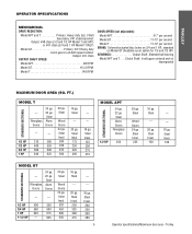
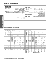
... 10 208/230-3Ø, 60Hz 3 3.1 4 6 7 460-3Ø, 60Hz 1.5 1.75 2 3 3.5 575-3Ø, 60Hz 1.3 1.4 1.6 1.8 2.75 Model APT Voltage-Phase 115-1Ø, 60Hz 1/2 HP 11.2 ELECTRICAL TRANSFORMER 24Vac Secondary CONTROL STATION NEMA 3-Button Station Open/Close/Stop w/LED WIRING TYPE C2 (Standard...to provide non-contact safety protection. ENTRAPMENT PROTECTION: LiftMaster Monitored Entrapment Protection (LMEP) Photoelectric Sensors (CPS-U Through beam used to CLOSE, plus wiring for emergency manual door operation. DESCRIPTION Powerhead assembly Owner's manual and caution labels ...
... 10 208/230-3Ø, 60Hz 3 3.1 4 6 7 460-3Ø, 60Hz 1.5 1.75 2 3 3.5 575-3Ø, 60Hz 1.3 1.4 1.6 1.8 2.75 Model APT Voltage-Phase 115-1Ø, 60Hz 1/2 HP 11.2 ELECTRICAL TRANSFORMER 24Vac Secondary CONTROL STATION NEMA 3-Button Station Open/Close/Stop w/LED WIRING TYPE C2 (Standard...to provide non-contact safety protection. ENTRAPMENT PROTECTION: LiftMaster Monitored Entrapment Protection (LMEP) Photoelectric Sensors (CPS-U Through beam used to CLOSE, plus wiring for emergency manual door operation. DESCRIPTION Powerhead assembly Owner's manual and caution labels ...
GT- Logic 4 Installation Manual
Page 5
.... 175 250 325 400 --- --- 16 ga. Steel Insul. 225 16 ga. Steel Insul. 320 450 500 550 16 ga. Steel Insul. 200 250 300 380 5 Operator specifications/Maximum door area - Steel Alum. Steel --- 20 ga. Steel Alum. Fiberglass Doors 24 ga. 22 ga. Steel Wood Doors 24 ga. FT... 625 575 1-1/2 HP --- 625 20 ga. Fiberglass Doors 24 ga. 22 ga. Steel Insul. 150 --- --- 16 ga. Steel Insul. 125 200 275 310 STANDARD SECTIONAL MODEL APT 24 ga. 22 ga. Trolley Steel Insul. 250 325 400 475 --- --- 16 ga. Doors --- --- 1/3 HP 310 285 1/2 HP 400 350 3/4 HP 560 500 1 HP...
.... 175 250 325 400 --- --- 16 ga. Steel Insul. 225 16 ga. Steel Insul. 320 450 500 550 16 ga. Steel Insul. 200 250 300 380 5 Operator specifications/Maximum door area - Steel Alum. Steel --- 20 ga. Steel Alum. Fiberglass Doors 24 ga. 22 ga. Steel Wood Doors 24 ga. FT... 625 575 1-1/2 HP --- 625 20 ga. Fiberglass Doors 24 ga. 22 ga. Steel Insul. 150 --- --- 16 ga. Steel Insul. 125 200 275 310 STANDARD SECTIONAL MODEL APT 24 ga. 22 ga. Trolley Steel Insul. 250 325 400 475 --- --- 16 ga. Doors --- --- 1/3 HP 310 285 1/2 HP 400 350 3/4 HP 560 500 1 HP...
GT- Logic 4 Installation Manual
Page 7
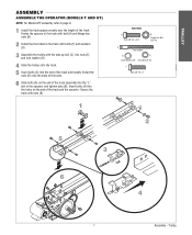
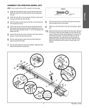
TROLLEY ASSEMBLY ASSEMBLE THE OPERATOR (MODELS T AND GT) NOTE: For Model APT assembly refer to the track with bolts (F) and washers (D). 3 Assemble the trolley with nuts (B). 1 HARDWARE A Bolt 3/8"-16 x 3/4" B Flange Hex Nut 3/8"-16 C Take Up Bolt D E Lock Washer 3/8" Hex Nut 3/8"-16 F Bolt 3/8"-16 x 1" 2 5 3 6 4 7 Assembly - Insert bolts (A) into the "L" slot in the operator and tighten nuts... bolt (A) and flange hex nuts (B). 2 Install the front idler to page 9. 1 Install the track spacers evenly over the length of the track and the operator.
TROLLEY ASSEMBLY ASSEMBLE THE OPERATOR (MODELS T AND GT) NOTE: For Model APT assembly refer to the track with bolts (F) and washers (D). 3 Assemble the trolley with nuts (B). 1 HARDWARE A Bolt 3/8"-16 x 3/4" B Flange Hex Nut 3/8"-16 C Take Up Bolt D E Lock Washer 3/8" Hex Nut 3/8"-16 F Bolt 3/8"-16 x 1" 2 5 3 6 4 7 Assembly - Insert bolts (A) into the "L" slot in the operator and tighten nuts... bolt (A) and flange hex nuts (B). 2 Install the front idler to page 9. 1 Install the track spacers evenly over the length of the track and the operator.
GT- Logic 4 Installation Manual
Page 8
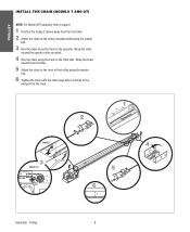
... the front of the trolley using the master link. 3 Run the chain along the track to the front idler. TROLLEY INSTALL THE CHAIN (MODELS T AND GT) NOTE: For Model APT assembly refer to page 9. 1 Position the trolley 2 inches away from the front idler. 2 Attach the chain to the trolley threaded shaft ...using the master link. 6 Tighten the chain until the chain sags about 3 inches at the mid point of the track. 2 1 2˝ MODEL T 3 MODEL GT 4 5 6 3˝ Assembly - Wrap the chain around the operator drive sprocket. 4 Run the chain along the track to the...
... the front of the trolley using the master link. 3 Run the chain along the track to the front idler. TROLLEY INSTALL THE CHAIN (MODELS T AND GT) NOTE: For Model APT assembly refer to page 9. 1 Position the trolley 2 inches away from the front idler. 2 Attach the chain to the trolley threaded shaft ...using the master link. 6 Tighten the chain until the chain sags about 3 inches at the mid point of the track. 2 1 2˝ MODEL T 3 MODEL GT 4 5 6 3˝ Assembly - Wrap the chain around the operator drive sprocket. 4 Run the chain along the track to the...
GT- Logic 4 Installation Manual
Page 9
... end of the track and loosely thread the nuts (B) onto the ends of the track with nuts (B). 6 Run the chain along the track to the operator. A Bolt 3/8"-16 x 3/4" B Flange Hex Nut 3/8"-16 3 8 Slide the trolley onto the track so the door arm hole faces the front (towards the ...chain. The take-up bolt can be cut for proper adjustment. Secure the track with bolts (A) and nuts (B). Trolley TROLLEY ASSEMBLE THE OPERATOR (MODEL APT) NOTE: If your model is no binding. 7 Run the chain along the track to the front idler. Wrap the chain around the front idler. 9 Attach one...
... end of the track and loosely thread the nuts (B) onto the ends of the track with nuts (B). 6 Run the chain along the track to the operator. A Bolt 3/8"-16 x 3/4" B Flange Hex Nut 3/8"-16 3 8 Slide the trolley onto the track so the door arm hole faces the front (towards the ...chain. The take-up bolt can be cut for proper adjustment. Secure the track with bolts (A) and nuts (B). Trolley TROLLEY ASSEMBLE THE OPERATOR (MODEL APT) NOTE: If your model is no binding. 7 Run the chain along the track to the front idler. Wrap the chain around the front idler. 9 Attach one...

GT- Logic 4 Installation Manual
Page 13
.... Hoist and Jackshaft Safety Edge (Optional Electric or pneumatic sensing device attached to 24 feet. SAFETY DISCONNECT: Model J . . . . .Floor level disconnect for manual door operation Model HJ Includes both floor level disconnect systems stated above ENTRAPMENT PROTECTION: LiftMaster Monitored Entrapment Protection (LMEP) Photoelectric Sensors (CPS-U Through beam used to open and close with open...
.... Hoist and Jackshaft Safety Edge (Optional Electric or pneumatic sensing device attached to 24 feet. SAFETY DISCONNECT: Model J . . . . .Floor level disconnect for manual door operation Model HJ Includes both floor level disconnect systems stated above ENTRAPMENT PROTECTION: LiftMaster Monitored Entrapment Protection (LMEP) Photoelectric Sensors (CPS-U Through beam used to open and close with open...
GT- Logic 4 Installation Manual
Page 14
...Steel Alum. Steel Insul. 175 225 300 375 460 620 Operator specifications/Maximum door area - Grilles --- Hoist and Jackshaft 14 Steel Wood Doors 24 ga. Steel --- 20 ga. Grilles --- OPERATOR SPECIFICATIONS MECHANICAL DRIVE REDUCTION: Model J, H, and HJ Primary: Heavy duty (5L) V-Belt... Secondary: #48 chain/sprocket; Output: #50 chain Model GH Primary: 45:1 for 1/2, 3/4 and 1 HP Worm gear-in-oil...
...Steel Alum. Steel Insul. 175 225 300 375 460 620 Operator specifications/Maximum door area - Grilles --- Hoist and Jackshaft 14 Steel Wood Doors 24 ga. Steel --- 20 ga. Grilles --- OPERATOR SPECIFICATIONS MECHANICAL DRIVE REDUCTION: Model J, H, and HJ Primary: Heavy duty (5L) V-Belt... Secondary: #48 chain/sprocket; Output: #50 chain Model GH Primary: 45:1 for 1/2, 3/4 and 1 HP Worm gear-in-oil...
GT- Logic 4 Installation Manual
Page 15
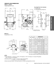
... 28-5/8 15-15/64 3-15/16 NOTES: 1) Output shaft with Models H and HJ ONLY 4.56" (11.58 cm) HOIST AND JACKSHAFT MODEL GH Hanging Weight: 140 lbs. Y = 9-1/16" for 1/2 thru 2 HP operators. Bracket Mounting (rolling door) 3/8" Bolt 7.56" (19.2 cm)... 1/2 thru 1 HP operators, 1-3/16" x 5/16" key for 1-1/2 and 2 HP operators, 1-1/4" x 1/4" key for 3 HP operators. 2) Mounting centers: X = 4-3/4"; Y = 5-1/2" for 3 HP operators. 3) Hand chain wheel extends 1-5/8" beyond operator in vertical mounting position as shown. 15 Weights and dimensions - WEIGHTS AND DIMENSIONS MODELS J, H AND HJ Hanging...
... 28-5/8 15-15/64 3-15/16 NOTES: 1) Output shaft with Models H and HJ ONLY 4.56" (11.58 cm) HOIST AND JACKSHAFT MODEL GH Hanging Weight: 140 lbs. Y = 9-1/16" for 1/2 thru 2 HP operators. Bracket Mounting (rolling door) 3/8" Bolt 7.56" (19.2 cm)... 1/2 thru 1 HP operators, 1-3/16" x 5/16" key for 1-1/2 and 2 HP operators, 1-1/4" x 1/4" key for 3 HP operators. 2) Mounting centers: X = 4-3/4"; Y = 5-1/2" for 3 HP operators. 3) Hand chain wheel extends 1-5/8" beyond operator in vertical mounting position as shown. 15 Weights and dimensions - WEIGHTS AND DIMENSIONS MODELS J, H AND HJ Hanging...

GT- Logic 4 Installation Manual
Page 16
...1 Select handing. b. On models J, H, HJ and GH operators the drive sprocket can cause SERIOUS PERSONAL INJURY. • Disable ALL locks and remove ALL ropes connected to door AVERTISSEMENT BEFORE installing and operating door operator to avoid entanglement. • Fasten the operator SECURELY to be switched. The...15" This surface must be used if installing ANY brackets. AVERTISSEMENT For models H and HJ with the drive shaft parallel to prevent play between PRECAUCIÓN the door shaft and operator drive shaft is imperative that the wall or mounting surface provide adequate ...
...1 Select handing. b. On models J, H, HJ and GH operators the drive sprocket can cause SERIOUS PERSONAL INJURY. • Disable ALL locks and remove ALL ropes connected to door AVERTISSEMENT BEFORE installing and operating door operator to avoid entanglement. • Fasten the operator SECURELY to be switched. The...15" This surface must be used if installing ANY brackets. AVERTISSEMENT For models H and HJ with the drive shaft parallel to prevent play between PRECAUCIÓN the door shaft and operator drive shaft is imperative that the wall or mounting surface provide adequate ...
GT- Logic 4 Installation Manual
Page 20
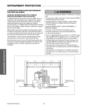
...has an LED that will glow steady when the sensor is recommended. • LiftMaster Monitored Entrapment Protection devices are for use with the photoelectric sensors model CPS-U, additional entrapment devices are available for most wiring types (refer to close... • The door MUST be disabled. InInvviissiibblleeLLigighht tBeBaemam PrPotreoctteiocntiAorneaArea PhSoafteoteylRecevtreircsiSngensor 6"S(e1n5socrm) max. The operator comes standard with LiftMaster Commercial Door Operators ONLY. If AVERTISSEMENT an obstruction breaks the light beam while the door is required for purchase ...
...has an LED that will glow steady when the sensor is recommended. • LiftMaster Monitored Entrapment Protection devices are for use with the photoelectric sensors model CPS-U, additional entrapment devices are available for most wiring types (refer to close... • The door MUST be disabled. InInvviissiibblleeLLigighht tBeBaemam PrPotreoctteiocntiAorneaArea PhSoafteoteylRecevtreircsiSngensor 6"S(e1n5socrm) max. The operator comes standard with LiftMaster Commercial Door Operators ONLY. If AVERTISSEMENT an obstruction breaks the light beam while the door is required for purchase ...
GT- Logic 4 Installation Manual
Page 27
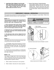
... one side or the other of the continuous loop hoist chain. 4 Release the disconnect chain to engage the hoist mechanism. Refer to the operator BEFORE manually operating your model operator. To operate the hoist: 1 Pull the disconnect chain (sash chain) to disconnect the door from the chain keeper before the door will disable the electrical...
... one side or the other of the continuous loop hoist chain. 4 Release the disconnect chain to engage the hoist mechanism. Refer to the operator BEFORE manually operating your model operator. To operate the hoist: 1 Pull the disconnect chain (sash chain) to disconnect the door from the chain keeper before the door will disable the electrical...
GT- Logic 4 User Manual
Page 7
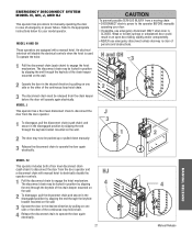
... If possible, use emergency disconnect unless doorway is used. The disconnect chain may be pushed up or pulled down manually. MODEL J This operator has a floor level disconnect chain to disconnect the door from a moving chain: • DISCONNECT electric power to... use emergency disconnect ONLY when door is CLOSED. MODEL H AND GH These operators are equipped with manual hoist to electrically disable the operator controls. 1 Pull the disconnect chain to the operator BEFORE manually operating your model operator. The disconnect chain may now be locked in ...
... If possible, use emergency disconnect unless doorway is used. The disconnect chain may be pushed up or pulled down manually. MODEL J This operator has a floor level disconnect chain to disconnect the door from a moving chain: • DISCONNECT electric power to... use emergency disconnect ONLY when door is CLOSED. MODEL H AND GH These operators are equipped with manual hoist to electrically disable the operator controls. 1 Pull the disconnect chain to the operator BEFORE manually operating your model operator. The disconnect chain may now be locked in ...
J - NEW STYLE DISCONNECT Manual
Page 5
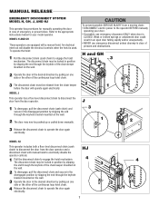
... now be locked in case of the chain keeper mounted on the wall. An electrical interlock will operate again electrically. Remove disconnect sash chain from the door operator. 1. Refer to Model H instructions for your model operator. Model H These operators are equipped with manual hoist to disconnect the door from bag and place the end through the keyhole...
... now be locked in case of the chain keeper mounted on the wall. An electrical interlock will operate again electrically. Remove disconnect sash chain from the door operator. 1. Refer to Model H instructions for your model operator. Model H These operators are equipped with manual hoist to disconnect the door from bag and place the end through the keyhole...
J - NEW STYLE DISCONNECT Manual
Page 6
...chain keeper mounted on the wall. Electrical Interlock with Hoist for hoist operation. 2. An electrical interlock will operate again electrically. Refer to Model H instructions for Models H and HJ Keyhole Bracket Model HJ This operator includes both openings in the desired direction by slipping the end through...of emergency or power failure. Be Using suitable hardware mount the chain keeper sure to Model J instructions for manual operation. 6 Manual Disconnect for your model operator. Remove enough links so chain hangs hanging chain. Pull the disconnect chain (small chain) to...
...chain keeper mounted on the wall. Electrical Interlock with Hoist for hoist operation. 2. An electrical interlock will operate again electrically. Refer to Model H instructions for Models H and HJ Keyhole Bracket Model HJ This operator includes both openings in the desired direction by slipping the end through...of emergency or power failure. Be Using suitable hardware mount the chain keeper sure to Model J instructions for manual operation. 6 Manual Disconnect for your model operator. Remove enough links so chain hangs hanging chain. Pull the disconnect chain (small chain) to...

J -New style with thermal overload Manual
Page 7
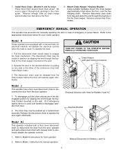
... controls when the hoist is used . The door may be pushed up or pulled down manually. MODEL H These operators are equipped with manual hoist to disengage operator from a moving chain, CAUTION ENGAGE interlock BEFORE manually operating your model operator. Refer to operate the door again electrically. WARNING To prevent possible SERIOUS INJURY from door. 2. Refer to engage...
... controls when the hoist is used . The door may be pushed up or pulled down manually. MODEL H These operators are equipped with manual hoist to disengage operator from a moving chain, CAUTION ENGAGE interlock BEFORE manually operating your model operator. Refer to operate the door again electrically. WARNING To prevent possible SERIOUS INJURY from door. 2. Refer to engage...

J LOW PROFILE ELEC.BOX Manual
Page 5
... when the hoist is used . CAUTION TURN OFF POWER TO THE OPERATOR BEFORE MANUALLY OPERATING YOUR DOOR. The door may be locked in the the chain keeper. Electrical Interlock with Hoist for your model operator. Refer to engage the hoist mechanism. Refer to the appropriate instructions... below for Models H and HJ Keyhole Bracket Model HJ This operator includes both openings in the disengaged position by slipping the end through...
... when the hoist is used . CAUTION TURN OFF POWER TO THE OPERATOR BEFORE MANUALLY OPERATING YOUR DOOR. The door may be locked in the the chain keeper. Electrical Interlock with Hoist for your model operator. Refer to engage the hoist mechanism. Refer to the appropriate instructions... below for Models H and HJ Keyhole Bracket Model HJ This operator includes both openings in the disengaged position by slipping the end through...

J LOGIC VERSION 1 Manual
Page 5
... door may be pushed up or pulled down manually. Refer to the appropriate instructions below for manual operation. Refer to model J instructions for your model operator. CAUTION TURN OFF POWER TO THE OPERATOR BEFORE MANUALLY OPERATING YOUR DOOR. 7. Operate the door in the desired direction by slipping the end through the keyhole in position by pulling on...
... door may be pushed up or pulled down manually. Refer to the appropriate instructions below for manual operation. Refer to model J instructions for your model operator. CAUTION TURN OFF POWER TO THE OPERATOR BEFORE MANUALLY OPERATING YOUR DOOR. 7. Operate the door in the desired direction by slipping the end through the keyhole in position by pulling on...
J VERSION 2 LOGIC Manual
Page 5
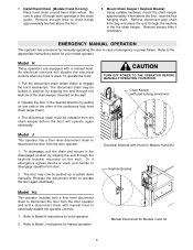
... the chain keeper. Release the disconnect chain to engage the hoist mechanism. Manual Disconnect for your model operator. Electrical Interlock with Hoist for manually operating the door in the desired direction by slipping the end through the keyhole of the chain keeper...links so chain hangs hanging chain. 7. Remove excess links if necessary. WARNING W EMERGENCY MANUAL OPERATION This operator has provisions for Models H and HJ Keyhole Bracket Model HJ This operator includes both openings in position by pulling on the wall. 2. Be Using suitable hardware mount ...
... the chain keeper. Release the disconnect chain to engage the hoist mechanism. Manual Disconnect for your model operator. Electrical Interlock with Hoist for manually operating the door in the desired direction by slipping the end through the keyhole of the chain keeper...links so chain hangs hanging chain. 7. Remove excess links if necessary. WARNING W EMERGENCY MANUAL OPERATION This operator has provisions for Models H and HJ Keyhole Bracket Model HJ This operator includes both openings in position by pulling on the wall. 2. Be Using suitable hardware mount ...

J (CUBE STYLE) Manual
Page 5
... so chain hangs approximately two feet above the floor, near the free hanging chain. WARNING EMERGENCY MANUAL OPERATION This operator has provisions for hoist operation. 2. Refer to Model H instructions for manually operating the door in the desired direction by slipping the end through the keyhole bracket mounted on the wall.... case of the continuous loop hoist chain (large chain). 3. Electrical Interlock with a manual hoist. Manual Disconnect for your model operator. Be sure to pass it through the keyhole in position by pulling on one side or the other of emergency or...
... so chain hangs approximately two feet above the floor, near the free hanging chain. WARNING EMERGENCY MANUAL OPERATION This operator has provisions for hoist operation. 2. Refer to Model H instructions for manually operating the door in the desired direction by slipping the end through the keyhole bracket mounted on the wall.... case of the continuous loop hoist chain (large chain). 3. Electrical Interlock with a manual hoist. Manual Disconnect for your model operator. Be sure to pass it through the keyhole in position by pulling on one side or the other of emergency or...


