
GT- Logic 4 Installation Manual
Page 2
... 7 Install the Chain (Models T and GT 8 Assemble the Operator (Model APT 9 TYPICAL INSTALLATION 10-12 Install the Header Bracket 10 Attach the Track to the Header Bracket 11 Hang the Operator 11 Attach the Door Arm 12 HOIST AND JACKSHAFT OPERATORS 13-17 Carton Inventory 13 Operator Specifications 13... the Manual Disconnect 17 WIRING 18-19 Power and Ground 18 Control Station 19 ENTRAPMENT PROTECTION 20-22 LiftMaster Monitored Entrapment Protection (LMEP 20 Install the Photoelectric Sensors (Provided 21 Mount the Photoelectric Sensors (Provided 22 Wire the...
... 7 Install the Chain (Models T and GT 8 Assemble the Operator (Model APT 9 TYPICAL INSTALLATION 10-12 Install the Header Bracket 10 Attach the Track to the Header Bracket 11 Hang the Operator 11 Attach the Door Arm 12 HOIST AND JACKSHAFT OPERATORS 13-17 Carton Inventory 13 Operator Specifications 13... the Manual Disconnect 17 WIRING 18-19 Power and Ground 18 Control Station 19 ENTRAPMENT PROTECTION 20-22 LiftMaster Monitored Entrapment Protection (LMEP 20 Install the Photoelectric Sensors (Provided 21 Mount the Photoelectric Sensors (Provided 22 Wire the...

GT- Logic 4 Installation Manual
Page 4
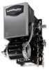
... Powerhead assembly Owner's manual and caution labels Hardware box (includes fasteners, track spacers, trolley, door arm assembly, front idler and header mounting bracket) 3-Button control station with open and close with LED Trolley drive chain: #48 for 1/3 and 1/2 HP, #41 for ...for emergency manual door operation. SAFETY DISCONNECT Quick disconnect door arm for optional wiring types and operating modes. ENTRAPMENT PROTECTION: LiftMaster Monitored Entrapment Protection (LMEP) Photoelectric Sensors (CPS-U Through beam used to the bottom edge of door. Safety Edge (Optional...
... Powerhead assembly Owner's manual and caution labels Hardware box (includes fasteners, track spacers, trolley, door arm assembly, front idler and header mounting bracket) 3-Button control station with open and close with LED Trolley drive chain: #48 for 1/3 and 1/2 HP, #41 for ...for emergency manual door operation. SAFETY DISCONNECT Quick disconnect door arm for optional wiring types and operating modes. ENTRAPMENT PROTECTION: LiftMaster Monitored Entrapment Protection (LMEP) Photoelectric Sensors (CPS-U Through beam used to the bottom edge of door. Safety Edge (Optional...
GT- Logic 4 Installation Manual
Page 10
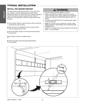
...ALWAYS call a trained door systems technician if door binds, sticks, or is generally mounted over the center of the door. DO NOT install header bracket over drywall. • Concrete anchors MUST be RIGIDLY fastened to interfering structures or location of door stile / top section support. Trolley 5 ...point of travel mark 4 inches above the highest point of travel. 3 Center the header bracket on header wall or ceiling, otherwise door might NOT reverse when required. AVERTISSEMENT 5 Fasten the header bracket with a vertical line, extend the line onto the ceiling. 2 Open the door ...
...ALWAYS call a trained door systems technician if door binds, sticks, or is generally mounted over the center of the door. DO NOT install header bracket over drywall. • Concrete anchors MUST be RIGIDLY fastened to interfering structures or location of door stile / top section support. Trolley 5 ...point of travel mark 4 inches above the highest point of travel. 3 Center the header bracket on header wall or ceiling, otherwise door might NOT reverse when required. AVERTISSEMENT 5 Fasten the header bracket with a vertical line, extend the line onto the ceiling. 2 Open the door ...
GT- Logic 4 Installation Manual
Page 11
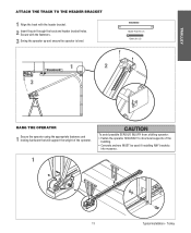
...Trolley TROLLEY ATTACH THE TRACK TO THE HEADER BRACKET 1 Align the track with the fasteners. 3 Swing the operator up and ensure the operator is level. Secure with the header bracket. 2 Insert the pin through the track and header bracket holes. CAUTION To avoid possible SERIOUS ...INJURY from a falling operator: • Fasten the operator SECURELY to structural supports of the operator. HARDWARE Header Pivot Pin (1) Cotter pins (2) 1...
...Trolley TROLLEY ATTACH THE TRACK TO THE HEADER BRACKET 1 Align the track with the fasteners. 3 Swing the operator up and ensure the operator is level. Secure with the header bracket. 2 Insert the pin through the track and header bracket holes. CAUTION To avoid possible SERIOUS ...INJURY from a falling operator: • Fasten the operator SECURELY to structural supports of the operator. HARDWARE Header Pivot Pin (1) Cotter pins (2) 1...

GT- Logic 4 Installation Manual
Page 13
See page 29 for manual door operation Model HJ Includes both floor level disconnect systems stated above ENTRAPMENT PROTECTION: LiftMaster Monitored Entrapment Protection (LMEP) Photoelectric Sensors (CPS-U Through beam used to open and close with LED Hoist ... provided. DESCRIPTION Powerhead assembly Owner's manual and caution labels Hardware box (includes fasteners, track spacers, trolley, door arm assembly, front idler and header mounting bracket) 3-Button control station with open override. SAFETY DISCONNECT: Model J . . . . .Floor level disconnect for manual door operation Model H ...
See page 29 for manual door operation Model HJ Includes both floor level disconnect systems stated above ENTRAPMENT PROTECTION: LiftMaster Monitored Entrapment Protection (LMEP) Photoelectric Sensors (CPS-U Through beam used to open and close with LED Hoist ... provided. DESCRIPTION Powerhead assembly Owner's manual and caution labels Hardware box (includes fasteners, track spacers, trolley, door arm assembly, front idler and header mounting bracket) 3-Button control station with open override. SAFETY DISCONNECT: Model J . . . . .Floor level disconnect for manual door operation Model H ...
J - NEW STYLE DISCONNECT Manual
Page 2
...Specifications 3 Safety Specifications 3 Weights & Dimensions 3 PREPARATION Track Assembly 4 Powerhead Attachment 4 Trolley Carriage/ Chain Attachment 4 INSTALLATION INSTRUCTIONS Mounting Header Bracket 5 Mounting Operator 5 Operator Support 6 Straight Arm Attachment 6 ENTRAPMENT PROTECTION ACCESSORIES Sensing Edges & Photo Eyes 7 LIMIT SWITCH ADJUSTMENT Limit ...19-50106M #50 CHAIN, 106 PITCH 1 40-6000 DOOR OPERATOR LABEL 1 77-10897 PARTS BAG 1 10-10893 CHAIN RETAINING BRACKET 1 14-10466 PLASTIC BAG 1 27-10199 CABLE TIE 5 1/2IN 1 80-207-19 KEY 1/4 X 1-1/2"LONG 1 27-...
...Specifications 3 Safety Specifications 3 Weights & Dimensions 3 PREPARATION Track Assembly 4 Powerhead Attachment 4 Trolley Carriage/ Chain Attachment 4 INSTALLATION INSTRUCTIONS Mounting Header Bracket 5 Mounting Operator 5 Operator Support 6 Straight Arm Attachment 6 ENTRAPMENT PROTECTION ACCESSORIES Sensing Edges & Photo Eyes 7 LIMIT SWITCH ADJUSTMENT Limit ...19-50106M #50 CHAIN, 106 PITCH 1 40-6000 DOOR OPERATOR LABEL 1 77-10897 PARTS BAG 1 10-10893 CHAIN RETAINING BRACKET 1 14-10466 PLASTIC BAG 1 27-10199 CABLE TIE 5 1/2IN 1 80-207-19 KEY 1/4 X 1-1/2"LONG 1 27-...


