Owners Manual
Page 1
OWNER'S MANUAL MODEL GH 5HP HEAVY DUTY DOOR OPERATOR FACTORY SET C2 Wiring See page 8 for other wiring configurations 2 YEAR WARRANTY Serial # (located on electrical box cover) Installation Date Wiring Type
OWNER'S MANUAL MODEL GH 5HP HEAVY DUTY DOOR OPERATOR FACTORY SET C2 Wiring See page 8 for other wiring configurations 2 YEAR WARRANTY Serial # (located on electrical box cover) Installation Date Wiring Type
Owners Manual
Page 2
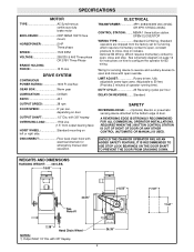
.../Sec GEAR BOX Worm gear LUBRICATION Oil Bath RATIO 45:1 OUTPUT SPEED 38 rpm DOOR SPEED 5" per hour DELAY ON REVERSE:.......Standard SAFETY REVERSING EDGE:.......(Optional) Electric or pneumatic sensing device attached to 50 feet. (Provides 2 minutes of door. DUTY CYCLE 25 Reversing cycles per sec. OPEN/CLOSE/STOP WIRING TYPE Standard C2 Wiring- Optional B2 Wiring- LIMIT ADJUST Rotary driven, fully adjustable screw type cams. Adjustable to the bottom edge of operator running time).
.../Sec GEAR BOX Worm gear LUBRICATION Oil Bath RATIO 45:1 OUTPUT SPEED 38 rpm DOOR SPEED 5" per hour DELAY ON REVERSE:.......Standard SAFETY REVERSING EDGE:.......(Optional) Electric or pneumatic sensing device attached to 50 feet. (Provides 2 minutes of door. DUTY CYCLE 25 Reversing cycles per sec. OPEN/CLOSE/STOP WIRING TYPE Standard C2 Wiring- Optional B2 Wiring- LIMIT ADJUST Rotary driven, fully adjustable screw type cams. Adjustable to the bottom edge of operator running time).

Owners Manual
Page 3
... A PROFESSIONAL DOOR SERVICEMAN TO MOVE OR ADJUST DOOR CAUTION SPRINGS OR HARDWARE. STEEL USE 5/8" DIA. BOLT OPTIONAL MOUNTING PLATE (SEE PAGE 16) OPERATOR PREPARATION The GH operator may be adversely affected if any of door, and in a horizontal position. In reverse of disassembly, install the chain wheel assembly on the opposite side of the gear hoist housing. IF THE DOOR LOCK NEEDS TO REMAIN FUNCTIONAL, INSTALL AN INTERLOCK SWITCH...
... A PROFESSIONAL DOOR SERVICEMAN TO MOVE OR ADJUST DOOR CAUTION SPRINGS OR HARDWARE. STEEL USE 5/8" DIA. BOLT OPTIONAL MOUNTING PLATE (SEE PAGE 16) OPERATOR PREPARATION The GH operator may be adversely affected if any of door, and in a horizontal position. In reverse of disassembly, install the chain wheel assembly on the opposite side of the gear hoist housing. IF THE DOOR LOCK NEEDS TO REMAIN FUNCTIONAL, INSTALL AN INTERLOCK SWITCH...
Owners Manual
Page 4
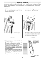
... key at this time. 2. Wrap drive chain around door sprocket and join roller chain ends together with drive before securing to the illustration and instructions below the door shaft. Make sure the operator output shaft is working smoothly. Chain Keeper FIGURE 5 OPERATOR MOUNTING Before your application. Refer to approximate mounting position using suitable lifting apparatus and position chain over operator sprocket. 5. Raise operator to Figure 4. When in position, secure the operator to Figure 3. 1b. Refer to wall or mounting bracket...
... key at this time. 2. Wrap drive chain around door sprocket and join roller chain ends together with drive before securing to the illustration and instructions below the door shaft. Make sure the operator output shaft is working smoothly. Chain Keeper FIGURE 5 OPERATOR MOUNTING Before your application. Refer to approximate mounting position using suitable lifting apparatus and position chain over operator sprocket. 5. Raise operator to Figure 4. When in position, secure the operator to Figure 3. 1b. Refer to wall or mounting bracket...

Owners Manual
Page 5
... power failure. Remove disconnect sash chain from the chain keeper before the door will disable the electrical controls when the hoist is against the chain keeper and at the same time, the bevel gears located in the operator hoist mechanism are in the chain keeper and lock into place by tightening the set screw. Install locking collar onto the disconnect chain. Model GH 5HP This operator is equipped with pad locking provisions) Manual Hoist 5 Remove...
... power failure. Remove disconnect sash chain from the chain keeper before the door will disable the electrical controls when the hoist is against the chain keeper and at the same time, the bevel gears located in the operator hoist mechanism are in the chain keeper and lock into place by tightening the set screw. Install locking collar onto the disconnect chain. Model GH 5HP This operator is equipped with pad locking provisions) Manual Hoist 5 Remove...
Owners Manual
Page 6
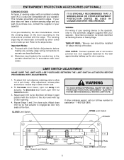
... door manufacturer, mount the sensing edge on the door according to the schematic diagram supplied with top of door opening . To adjust limit nuts depress retaining plate to allow nut to the wall approximately halfway up reel. If your door does not have a bottom sensing edge and you wish to operator as Sensing Device or Safety Edge. Important Notes: a) Proceed with local codes. After adjustment, release...
... door manufacturer, mount the sensing edge on the door according to the schematic diagram supplied with top of door opening . To adjust limit nuts depress retaining plate to allow nut to the wall approximately halfway up reel. If your door does not have a bottom sensing edge and you wish to operator as Sensing Device or Safety Edge. Important Notes: a) Proceed with local codes. After adjustment, release...
Owners Manual
Page 7
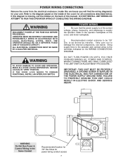
... cover, and motor nameplate. 2. Bring supply lines to the operator and connect wires to the operator nameplate on the WIRING CONNECTIONS DIAGRAM. WARNING TO AVOID DAMAGE TO DOOR AND OPERATOR, MAKE ALL DOOR LOCKS INOPERATIVE. CAUTION DO NOT TURN POWER ON UNTIL YOU HAVE WARNING FINISHED MAKING ALL POWER AND CONTROL WIRING CONNECTIONS AND HAVE COMPLETED THE LIMIT SWITCH ADJUSTMENT PROCEDURE. IF THE DOOR LOCK NEEDS TO REMAIN FUNCTIONAL, INSTALL AN INTERLOCK SWITCH. Inside this manual. A GROUND SCREW...
... cover, and motor nameplate. 2. Bring supply lines to the operator and connect wires to the operator nameplate on the WIRING CONNECTIONS DIAGRAM. WARNING TO AVOID DAMAGE TO DOOR AND OPERATOR, MAKE ALL DOOR LOCKS INOPERATIVE. CAUTION DO NOT TURN POWER ON UNTIL YOU HAVE WARNING FINISHED MAKING ALL POWER AND CONTROL WIRING CONNECTIONS AND HAVE COMPLETED THE LIMIT SWITCH ADJUSTMENT PROCEDURE. IF THE DOOR LOCK NEEDS TO REMAIN FUNCTIONAL, INSTALL AN INTERLOCK SWITCH. Inside this manual. A GROUND SCREW...
Owners Manual
Page 8
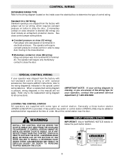
... only to close the door. MOUNT WARNING NOTICE WARNING IMPORTANT: Mount WARNING NOTICE beside or below . Control Station Push Buttons OPEN WARNING CLOSE TO PREVENT ENTRAPMENT WARNING DO NOT START DOOR DOWNWARD UNLESS DOORWAY IS CLEAR STOP WARNING Notice 8 CONTROL WIRING DETERMINE WIRING TYPE Refer to the wiring diagram located on close (B2 wiring) Move red jumper wire from terminal #2 to terminal #3. Momentary contact on the inside cover the electrical box to determine the...
... only to close the door. MOUNT WARNING NOTICE WARNING IMPORTANT: Mount WARNING NOTICE beside or below . Control Station Push Buttons OPEN WARNING CLOSE TO PREVENT ENTRAPMENT WARNING DO NOT START DOOR DOWNWARD UNLESS DOORWAY IS CLEAR STOP WARNING Notice 8 CONTROL WIRING DETERMINE WIRING TYPE Refer to the wiring diagram located on close (B2 wiring) Move red jumper wire from terminal #2 to terminal #3. Momentary contact on the inside cover the electrical box to determine the...
Owners Manual
Page 9
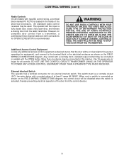
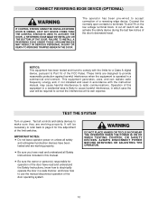
... complete door control from the radio transmitter. All standard radio control receivers may be a normally closed door, close a fully open a DO NOT USE RADIO CONTROLS WITH YOUR OPERATOR UNLESS YOU HAVE INSTALLED fully closed (N.C.) two-wire device with type B2 control wiring, a terminal WARNING W block marked R1 R2 R3 is actuated, thereby preventing electrical operation of at least 3 amps @ 24VAC. Additional Access Control Equipment Locate any additional access control equipment as shown on the FIELD WIRING CONNECTIONS diagram, the control circuit will...
... complete door control from the radio transmitter. All standard radio control receivers may be a normally closed door, close a fully open a DO NOT USE RADIO CONTROLS WITH YOUR OPERATOR UNLESS YOU HAVE INSTALLED fully closed (N.C.) two-wire device with type B2 control wiring, a terminal WARNING W block marked R1 R2 R3 is actuated, thereby preventing electrical operation of at least 3 amps @ 24VAC. Additional Access Control Equipment Locate any additional access control equipment as shown on the FIELD WIRING CONNECTIONS diagram, the control circuit will...
Owners Manual
Page 10
... against harmful interference when the equipment is likely to use the manual disconnect operation of the door's downward travel. BEFORE SERVICING OR ADJUSTING THE OPERATOR. TEST THE SYSTEM Turn on the low voltage terminal block. ALWAYS DISCONNECT POWER and entrapment protection devices have read and understand the Safety Instructions, know how to electrically operate the door in a safe manner, and know how to cause harmful interference...
... against harmful interference when the equipment is likely to use the manual disconnect operation of the door's downward travel. BEFORE SERVICING OR ADJUSTING THE OPERATOR. TEST THE SYSTEM Turn on the low voltage terminal block. ALWAYS DISCONNECT POWER and entrapment protection devices have read and understand the Safety Instructions, know how to electrically operate the door in a safe manner, and know how to cause harmful interference...

Owners Manual
Page 11
... ORDER REPAIR PARTS OUR LARGE SERVICE ORGANIZATION SPANS AMERICA INSTALLATION AND SERVICE INFORMATION ARE AVAILABLE 6 DAYS A WEEK CALL OUR TOLL FREE NUMBER - 1-800-528-2806 HOURS 7:00 TO 3:30 p.m. (Mountain Std. Lubricate.* Check set screw tightness Check & tighten as required. Inspect and service whenever a malfunction is Polyrex EM (Exxon Mobile). Motor grease fitting to be greased every 12,000 Hrs. ITEM Drive Chain Sprockets Fasteners Manual...
... ORDER REPAIR PARTS OUR LARGE SERVICE ORGANIZATION SPANS AMERICA INSTALLATION AND SERVICE INFORMATION ARE AVAILABLE 6 DAYS A WEEK CALL OUR TOLL FREE NUMBER - 1-800-528-2806 HOURS 7:00 TO 3:30 p.m. (Mountain Std. Lubricate.* Check set screw tightness Check & tighten as required. Inspect and service whenever a malfunction is Polyrex EM (Exxon Mobile). Motor grease fitting to be greased every 12,000 Hrs. ITEM Drive Chain Sprockets Fasteners Manual...

Owners Manual
Page 13
THREE PHASE FIELD WIRING 1942 13
THREE PHASE FIELD WIRING 1942 13
Owners Manual
Page 14
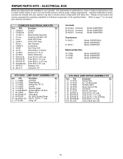
.... REPAIR PARTS KITS - Optional modifications and/or accessories included with your operator. Please consult a parts and service representative regarding availability of individual components of your unit to kit number below . Refer to match model number of kits specified below to ensure proper voltage requirements. Bracket 1 S3 10-12553 Nut Plate, Switch 4 S4 18-10036 Spring, Depress Plate 2 S5 23-10041 Limit Switch 4 S6 31-12378 Standoff, Limit Switch 4 S7...
.... REPAIR PARTS KITS - Optional modifications and/or accessories included with your operator. Please consult a parts and service representative regarding availability of individual components of your unit to kit number below . Refer to match model number of kits specified below to ensure proper voltage requirements. Bracket 1 S3 10-12553 Nut Plate, Switch 4 S4 18-10036 Spring, Depress Plate 2 S5 23-10041 Limit Switch 4 S6 31-12378 Standoff, Limit Switch 4 S7...
Owners Manual
Page 15
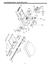
ILLUSTRATED PARTS - ELECTRICAL BOX WARNING WARNING 15
ILLUSTRATED PARTS - ELECTRICAL BOX WARNING WARNING 15
Owners Manual
Page 16
... - Bolt 2 B12 85-LS-25 Lock Washer for 1/4 Dia. If optional modifications and/or accessories are included with your operator. x 1.25 Long Roll Pin, 1/4" x 1-3/4" Long Roll Pin, 5/16" x 2-1/2" Long E-Ring, 3/4" QTY 1 1 1 2 1 1 2 5 1 1 2 3 K75-18180 MOTOR BRAKE ASSEMBLY KITS ITEM PART # DESCRIPTION QTY B1 10-17996 Brake Release Bracket 1 B2 10-17997 Brake Motor Release Arm 1 B3 10-18057 Motor, Brake Cover (Reworked) 1 B4 12-18074-1 Flanged...
... - Bolt 2 B12 85-LS-25 Lock Washer for 1/4 Dia. If optional modifications and/or accessories are included with your operator. x 1.25 Long Roll Pin, 1/4" x 1-3/4" Long Roll Pin, 5/16" x 2-1/2" Long E-Ring, 3/4" QTY 1 1 1 2 1 1 2 5 1 1 2 3 K75-18180 MOTOR BRAKE ASSEMBLY KITS ITEM PART # DESCRIPTION QTY B1 10-17996 Brake Release Bracket 1 B2 10-17997 Brake Motor Release Arm 1 B3 10-18057 Motor, Brake Cover (Reworked) 1 B4 12-18074-1 Flanged...
Owners Manual
Page 20
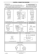
... 37 SEE NOTES #2 AND #3 Open Open Open Close ALL CONTROL WIRING TYPES Close Close ALL CONTROL WIRING TYPES SENSING DEVICE TO REVERSE OR STOP OPEN / CLOSE B2 WIRING TYPES ONLY RADIO CONTROLS 3 10 R1 R2 R3 LOCATED ON MAIN TERMINAL BLOCK Sensing Device ALL CONTROL WIRING TYPES EXTERNAL INTERLOCK Remove Jumper When Interlock is not used, a jumper must be any normally open two wire device such as pullswitch, single button, loop detector, card key or such device. All rights...
... 37 SEE NOTES #2 AND #3 Open Open Open Close ALL CONTROL WIRING TYPES Close Close ALL CONTROL WIRING TYPES SENSING DEVICE TO REVERSE OR STOP OPEN / CLOSE B2 WIRING TYPES ONLY RADIO CONTROLS 3 10 R1 R2 R3 LOCATED ON MAIN TERMINAL BLOCK Sensing Device ALL CONTROL WIRING TYPES EXTERNAL INTERLOCK Remove Jumper When Interlock is not used, a jumper must be any normally open two wire device such as pullswitch, single button, loop detector, card key or such device. All rights...


