
EL25-KEYPAD PROGRAMMING Manual
Page 2
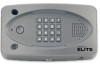
CCTV Camera: Optional 2. Status LED: Solid Red (EL25 idle power, doors are for door 1 is unlocked). Pound Key: Data field separator, optional skip step or enter key. Lights: Top and Bottom of Keypad. ... will return to communicate programming or function commands. 12. Speaker: Allows resident and visitors to programmed volume setting when transaction complete. 8. Status LED: Solid Red (EL2000 idle power, doors are for a door is unlocked). CCTV Camera: Optional 2. Pound Key: Data field separator, optional skip step or enter key. Call Button: Press...
CCTV Camera: Optional 2. Status LED: Solid Red (EL25 idle power, doors are for door 1 is unlocked). Pound Key: Data field separator, optional skip step or enter key. Lights: Top and Bottom of Keypad. ... will return to communicate programming or function commands. 12. Speaker: Allows resident and visitors to programmed volume setting when transaction complete. 8. Status LED: Solid Red (EL2000 idle power, doors are for a door is unlocked). CCTV Camera: Optional 2. Pound Key: Data field separator, optional skip step or enter key. Call Button: Press...
EL25-KEYPAD PROGRAMMING Manual
Page 15
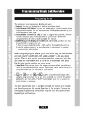
... settings in the system. Two areas that allows you to enter single transmitters or cards by scanning them to set up a basic system. EL2000 Keypad with Display: On EL2000 units with a direct or modem connection, your touch-tone phone (next page). 3. There is also a quick start menu selection, numerous help you to...
... settings in the system. Two areas that allows you to enter single transmitters or cards by scanning them to set up a basic system. EL2000 Keypad with Display: On EL2000 units with a direct or modem connection, your touch-tone phone (next page). 3. There is also a quick start menu selection, numerous help you to...

EL25-KEYPAD PROGRAMMING Manual
Page 73
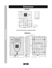
Keypad Template EL2000 LCD Programming Template Help Cursor Cursor Cursor A ABC Select Value 123 Tab 123 Z ABC Clear ® Enter 123 Number A B C Text Keypad Template Keypad Template Page 72
Keypad Template EL2000 LCD Programming Template Help Cursor Cursor Cursor A ABC Select Value 123 Tab 123 Z ABC Clear ® Enter 123 Number A B C Text Keypad Template Keypad Template Page 72

EL25 - INSTALLATION Manual
Page 3
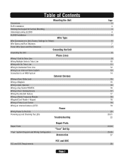
Table of Contents Mounting the Unit Dimensions EL25 Installation Rotating the Keypad for Vertical Mounting Unlocking/Locking EL2000 EL2000 Installation Wire Type Wire Connections to Unit (Factory Settings for Relays) Wire Specs and Run Distances Power Wire Specs and Run Distances Grounding the Unit ...
Table of Contents Mounting the Unit Dimensions EL25 Installation Rotating the Keypad for Vertical Mounting Unlocking/Locking EL2000 EL2000 Installation Wire Type Wire Connections to Unit (Factory Settings for Relays) Wire Specs and Run Distances Power Wire Specs and Run Distances Grounding the Unit ...
EL25 - INSTALLATION Manual
Page 4
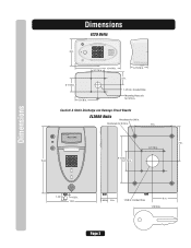
Conduit Hole Page 2 A Static Discharge can Damage Circuit Boards EL2000 Units Knockouts for 3/8 in . Knockouts for 5/16 in . Conduit Hole Mounting Holes (4) for 5/16 in. 9 in . Caution! Dimensions EL25 Units 6 in. 3-15/16 in. 3/4 in . AUG 10, 2005 WELCOME 7 in. 3-1/16 in. 15 in. 9-1/2 in. 3-1/16 in . Dimensions 1-1/2 in. 1/2 in. 12 in. 6 in. 1-5/8 in. 2 in. 1-1/4 in .
Conduit Hole Page 2 A Static Discharge can Damage Circuit Boards EL2000 Units Knockouts for 3/8 in . Knockouts for 5/16 in . Conduit Hole Mounting Holes (4) for 5/16 in. 9 in . Caution! Dimensions EL25 Units 6 in. 3-15/16 in. 3/4 in . AUG 10, 2005 WELCOME 7 in. 3-1/16 in. 15 in. 9-1/2 in. 3-1/16 in . Dimensions 1-1/2 in. 1/2 in. 12 in. 6 in. 1-5/8 in. 2 in. 1-1/4 in .
EL25 - INSTALLATION Manual
Page 6
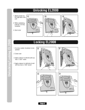
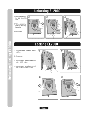
pressure, turn key 456 789 *0 # clockw# ise 3. Apply pressure to right-side of the unit. 2. # # # # # # Unlocking EL2000 1. While maintaining 123? Open cover 2 # # # 1 23? 456 789 *0 # 3 1 4 2 5 3 6 ? 789 * #0 # # Unlocking/Locking EL2000 Locking EL2000 1. Turn key counter clockwise to 1 the right-side of unit until you hear a "click" sound # # # # 3 123? 456 789 *0 # # # 4 1 #2 3 ? 456 789 *0 # Page 4 Close cover...
pressure, turn key 456 789 *0 # clockw# ise 3. Apply pressure to right-side of the unit. 2. # # # # # # Unlocking EL2000 1. While maintaining 123? Open cover 2 # # # 1 23? 456 789 *0 # 3 1 4 2 5 3 6 ? 789 * #0 # # Unlocking/Locking EL2000 Locking EL2000 1. Turn key counter clockwise to 1 the right-side of unit until you hear a "click" sound # # # # 3 123? 456 789 *0 # # # 4 1 #2 3 ? 456 789 *0 # Page 4 Close cover...

EL25 - INSTALLATION Manual
Page 7
EL2000 Model Installation EL2000 Installation NOTE: This unit is for surface and recessed mount ONLY. 1 Unlock Unit 2 Open Cover 1 23? 456 789 *0 # # 1 4 2 5 3 6 ? 789 # *0 # 3 Unplug the 2 Main Harnesses (Optional) 4 Slide Front Cover Out of Hinges (Optional) # 5 Knock-out Desired Mounting Plugs Using Punch 6 Mount Back Housing to Wall or Pedestal Page 5
EL2000 Model Installation EL2000 Installation NOTE: This unit is for surface and recessed mount ONLY. 1 Unlock Unit 2 Open Cover 1 23? 456 789 *0 # # 1 4 2 5 3 6 ? 789 # *0 # 3 Unplug the 2 Main Harnesses (Optional) 4 Slide Front Cover Out of Hinges (Optional) # 5 Knock-out Desired Mounting Plugs Using Punch 6 Mount Back Housing to Wall or Pedestal Page 5
EL25 - INSTALLATION Manual
Page 21
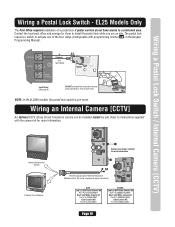
...Coaxial Cable 1000 Feet Maximum (Monitor with programming number 69 , in the Keypad Programming Manual). NOTE: In the EL2000 models, the postal lock switch is pre-wired. Refer to a controlled area. EL25 Models Only The Post Office requires installation of the four relays (Configurable with a .25 volt p-p composite signal ...sensitivity) EL25 EL2000 Page 19 The postal lock requires a switch to install the postal lock while you are on site. J7 J6 POSTAL J3 In N.C. ...
...Coaxial Cable 1000 Feet Maximum (Monitor with programming number 69 , in the Keypad Programming Manual). NOTE: In the EL2000 models, the postal lock switch is pre-wired. Refer to a controlled area. EL25 Models Only The Post Office requires installation of the four relays (Configurable with a .25 volt p-p composite signal ...sensitivity) EL25 EL2000 Page 19 The postal lock requires a switch to install the postal lock while you are on site. J7 J6 POSTAL J3 In N.C. ...

EL25 - INSTALLATION Manual
Page 23
... or 10.2 VDC at power block J1 to confirm. This button will turn on Model EL25 EL2000 X X X X X X X X X X X X X X X X X X X X X X X X X Name PWR LED 20-Pin Connector to IO Input Board LCD PWR EL25=LED BOTTOM KEYPAD EL2000=LED keypad MIC 14-Pin Connector to Output Board KEYPAD Local Mode RES DAA OFF HOOK ...or Wiegand-J1) or 2 (Wiegand-J2) Data wires for main keypad. For the EL25 provides power to Resident Resident side of circuit is the top lighted LEDs for the main keypad. On the EL2000 this is off hook Telco side of 16.5 VAC or 22.3 VDC at power block ...
... or 10.2 VDC at power block J1 to confirm. This button will turn on Model EL25 EL2000 X X X X X X X X X X X X X X X X X X X X X X X X X Name PWR LED 20-Pin Connector to IO Input Board LCD PWR EL25=LED BOTTOM KEYPAD EL2000=LED keypad MIC 14-Pin Connector to Output Board KEYPAD Local Mode RES DAA OFF HOOK ...or Wiegand-J1) or 2 (Wiegand-J2) Data wires for main keypad. For the EL25 provides power to Resident Resident side of circuit is the top lighted LEDs for the main keypad. On the EL2000 this is off hook Telco side of 16.5 VAC or 22.3 VDC at power block ...

EL25 - INSTALLATION Manual
Page 26
... Assembly, PCB Input Board 5 Assembly EL Main Board 6 Assembly, 20-Pin Input Board Cable 7 Assembly, 14-Pin Output Board Cable 8 EL2000 Housing Assembly (Black) EL2000 Housing Assembly (Gray) EL2000 Housing Assembly (Nickel) 9 Door Interconnect Cables Kit 10 Assembly, Speaker EL Series 11 Assembly, Call Button Board... 41B989 41B990 2B737 2B736 2B735 2B705 2B704 41B991 41B992 41B993 41B994 2B639 41B995 41B996 13 Interconnect Board 14 Assembly, Lock and Key EL2000 15 Replacement Key 16 Assembly, Keypad 16 Button 17 Gasket, Keypad 18 Assembly, Mike Cable EL Series 19 Assembly, Entry LED...
... Assembly, PCB Input Board 5 Assembly EL Main Board 6 Assembly, 20-Pin Input Board Cable 7 Assembly, 14-Pin Output Board Cable 8 EL2000 Housing Assembly (Black) EL2000 Housing Assembly (Gray) EL2000 Housing Assembly (Nickel) 9 Door Interconnect Cables Kit 10 Assembly, Speaker EL Series 11 Assembly, Call Button Board... 41B989 41B990 2B737 2B736 2B735 2B705 2B704 41B991 41B992 41B993 41B994 2B639 41B995 41B996 13 Interconnect Board 14 Assembly, Lock and Key EL2000 15 Replacement Key 16 Assembly, Keypad 16 Button 17 Gasket, Keypad 18 Assembly, Mike Cable EL Series 19 Assembly, Entry LED...
EL25 - INSTALLATION Manual
Page 29
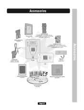
Accessories Accessories Wiegand Module Kit WOMODKT Directory Insert ELDI EL25 Camera Kits EL25BWCAMKT (Black & White Camera) EL25DVRCAMKT (Low Lux DVR Color Camera) EL25CAMKT (Color Camera) EL2000 Camera Kits EL2000BWCAMKT (Black & White Camera) EL2000DVRCAMKT (Low Lux DVR Color Camera) EL2000CAMKT (Color ...Camera) RF Module Kit RFMODKT (390 MHz) RFMODKT3 (315 MHz) 123 456 789 *0# Wiegand Remote Keypad ESSWOKSG EL2000 EL25 Heater Kit ELHTRKT EL2000 ONLY ? Click the DOORS Tab 4 Click OK 1 Rename "Door 1" to Ver sa 5. Click the Unit Configuration ICON 1 ...
Accessories Accessories Wiegand Module Kit WOMODKT Directory Insert ELDI EL25 Camera Kits EL25BWCAMKT (Black & White Camera) EL25DVRCAMKT (Low Lux DVR Color Camera) EL25CAMKT (Color Camera) EL2000 Camera Kits EL2000BWCAMKT (Black & White Camera) EL2000DVRCAMKT (Low Lux DVR Color Camera) EL2000CAMKT (Color ...Camera) RF Module Kit RFMODKT (390 MHz) RFMODKT3 (315 MHz) 123 456 789 *0# Wiegand Remote Keypad ESSWOKSG EL2000 EL25 Heater Kit ELHTRKT EL2000 ONLY ? Click the DOORS Tab 4 Click OK 1 Rename "Door 1" to Ver sa 5. Click the Unit Configuration ICON 1 ...
EL25 Installation Ver. 3.0 Manual
Page 3
Table of Contents Mounting the Unit Dimensions EL25 Installation Rotating the Keypad for Vertical Mounting Unlocking/Locking EL2000 EL2000 Installation Wire Type Wire Connections to Unit (Factory Settings for Relays) Wire Specs and Run Distances Power Wire Specs and Run Distances Grounding the Unit ...
Table of Contents Mounting the Unit Dimensions EL25 Installation Rotating the Keypad for Vertical Mounting Unlocking/Locking EL2000 EL2000 Installation Wire Type Wire Connections to Unit (Factory Settings for Relays) Wire Specs and Run Distances Power Wire Specs and Run Distances Grounding the Unit ...
EL25 Installation Ver. 3.0 Manual
Page 4
Dimensions EL25 Units 6 in. 3-1/16 in. 10-1/4 in. 3-15/16 in. 3-1/16 in. 5-1/8 in. 3 in. 1-1/16 in . Knockouts for 5/16 in. 9 in . Conduit Hole 6 in. 1-15/16 in . Caution! Dimensions 1-1/2 in. 1/2 in. 12 in. 1-5/8 in. 2 in. 1-5/8 in . Conduit Hole Mounting Holes (4) for 3/8 in . A Static Discharge can Damage Circuit Boards EL2000 Units Knockouts for 5/16 in . AUG 10, 2005 WELCOME 7 in. 3-1/16 in. 15 in. 9-1/2 in. 3-1/16 in. Page 2
Dimensions EL25 Units 6 in. 3-1/16 in. 10-1/4 in. 3-15/16 in. 3-1/16 in. 5-1/8 in. 3 in. 1-1/16 in . Knockouts for 5/16 in. 9 in . Conduit Hole 6 in. 1-15/16 in . Caution! Dimensions 1-1/2 in. 1/2 in. 12 in. 1-5/8 in. 2 in. 1-5/8 in . Conduit Hole Mounting Holes (4) for 3/8 in . A Static Discharge can Damage Circuit Boards EL2000 Units Knockouts for 5/16 in . AUG 10, 2005 WELCOME 7 in. 3-1/16 in. 15 in. 9-1/2 in. 3-1/16 in. Page 2
EL25 Installation Ver. 3.0 Manual
Page 6
... cover. 2 # # # 1 23? 456 789 *0 # 3 1 4 2 5 3 6 ? 789 * #0 # # Unlocking/Locking EL2000 Locking EL2000 1. Apply pressure to 1 the right-side of unit until you hear a "click" sound. # # # # 3 123? 456 789 *0 # # # 4 1 #2 3 ? 456 789 *0 # Page 4 Apply pressure to left-side until ...
... cover. 2 # # # 1 23? 456 789 *0 # 3 1 4 2 5 3 6 ? 789 * #0 # # Unlocking/Locking EL2000 Locking EL2000 1. Apply pressure to 1 the right-side of unit until you hear a "click" sound. # # # # 3 123? 456 789 *0 # # # 4 1 #2 3 ? 456 789 *0 # Page 4 Apply pressure to left-side until ...

EL25 Installation Ver. 3.0 Manual
Page 7
Page 5 EL2000 Model Installation EL2000 Installation NOTE: This unit is for surface and recessed mount ONLY. 1 Unlock Unit. 2 Open Cover. 1 23? 456 789 *0 # # 1 4 2 5 3 6 ? 789 # *0 # 3 Unplug the 2 Main Harnesses (Optional). 4 Slide Front Cover Out of Hinges (Optional). # 5 Knock-out Desired Mounting Plugs Using Punch. 6 Mount Back Housing to Wall or Pedestal.
Page 5 EL2000 Model Installation EL2000 Installation NOTE: This unit is for surface and recessed mount ONLY. 1 Unlock Unit. 2 Open Cover. 1 23? 456 789 *0 # # 1 4 2 5 3 6 ? 789 # *0 # 3 Unplug the 2 Main Harnesses (Optional). 4 Slide Front Cover Out of Hinges (Optional). # 5 Knock-out Desired Mounting Plugs Using Punch. 6 Mount Back Housing to Wall or Pedestal.

EL25 Installation Ver. 3.0 Manual
Page 21
... Lock Switch / Internal Camera (CCTV) Wiring a Postal Lock Switch - J7 J6 POSTAL J3 In N.C. NOTE: In the EL2000 models, the postal lock switch is pre-wired. Home Entertainment System A Closed Circuit Monitor Contact your dealer/ installer for more information...with programming number 69 , in the Keypad Programming Manual). One wire per hole. EL25 Models Only The Post Office requires installation of the four relays (Configurable with a .25 volt p-p composite signal sensitivity) EL25 EL2000 Page 19 Wiring an Internal Camera [CCTV] An Optional CCTV (Close Circuit Television)...
... Lock Switch / Internal Camera (CCTV) Wiring a Postal Lock Switch - J7 J6 POSTAL J3 In N.C. NOTE: In the EL2000 models, the postal lock switch is pre-wired. Home Entertainment System A Closed Circuit Monitor Contact your dealer/ installer for more information...with programming number 69 , in the Keypad Programming Manual). One wire per hole. EL25 Models Only The Post Office requires installation of the four relays (Configurable with a .25 volt p-p composite signal sensitivity) EL25 EL2000 Page 19 Wiring an Internal Camera [CCTV] An Optional CCTV (Close Circuit Television)...

EL25 Installation Ver. 3.0 Manual
Page 23
...Wiegand-J2). Main Speaker. Page 21 Battery used to confirm. Turns on Model EL25 EL2000 X X X X X X X X X X X X X X X X X X X X X X X X X Name PWR LED 20-Pin Connector to IO Input Board LCD PWR EL25=LED BOTTOM KEYPAD EL2000=LED keypad MIC 14-Pin Connector to confirm. Measure the voltage at power block...power condition still exists then the OV or UV LEDs may turn off hook. Provides power to LCD Display. On the EL2000 this is off the OV/UV LEDs momentarily. Turns on again. Reboots firmware without removing power. The IO Input Board ...
...Wiegand-J2). Main Speaker. Page 21 Battery used to confirm. Turns on Model EL25 EL2000 X X X X X X X X X X X X X X X X X X X X X X X X X Name PWR LED 20-Pin Connector to IO Input Board LCD PWR EL25=LED BOTTOM KEYPAD EL2000=LED keypad MIC 14-Pin Connector to confirm. Measure the voltage at power block...power condition still exists then the OV or UV LEDs may turn off hook. Provides power to LCD Display. On the EL2000 this is off the OV/UV LEDs momentarily. Turns on again. Reboots firmware without removing power. The IO Input Board ...

EL25 Installation Ver. 3.0 Manual
Page 26
... Assembly, PCB Input Board 5 Assembly EL Main Board 6 Assembly, 20-Pin Input Board Cable 7 Assembly, 14-Pin Output Board Cable 8 EL2000 Housing Assembly (Black) EL2000 Housing Assembly (Gray) EL2000 Housing Assembly (Nickel) 9 Door Interconnect Cables Kit 10 Assembly, Speaker EL Series 11 Assembly, Call Button Board... 41B989 41B990 2B737 2B736 2B735 2B705 2B704 41B991 41B992 41B993 41B994 2B639 41B995 41B996 13 Interconnect Board 14 Assembly, Lock and Key EL2000 15 Replacement Key 16 Assembly, Keypad 16 Button 17 Gasket, Keypad 18 Assembly, Mike Cable EL Series 19 Assembly, Entry LED...
... Assembly, PCB Input Board 5 Assembly EL Main Board 6 Assembly, 20-Pin Input Board Cable 7 Assembly, 14-Pin Output Board Cable 8 EL2000 Housing Assembly (Black) EL2000 Housing Assembly (Gray) EL2000 Housing Assembly (Nickel) 9 Door Interconnect Cables Kit 10 Assembly, Speaker EL Series 11 Assembly, Call Button Board... 41B989 41B990 2B737 2B736 2B735 2B705 2B704 41B991 41B992 41B993 41B994 2B639 41B995 41B996 13 Interconnect Board 14 Assembly, Lock and Key EL2000 15 Replacement Key 16 Assembly, Keypad 16 Button 17 Gasket, Keypad 18 Assembly, Mike Cable EL Series 19 Assembly, Entry LED...

EL25 Installation Ver. 3.0 Manual
Page 29
...PCroouvn. Accessories Accessories Wiegand Module Kit WOMODKT Directory Insert ELDI EL25 Camera Kits EL25BWCAMKT (Black & White Camera) EL25DVRCAMKT (Low Lux DVR Color Camera) EL25CAMKT (Color Camera) EL2000 Camera Kits EL2000BWCAMKT (Black & White Camera) EL2000DVRCAMKT (Low...390 MHz) RFMODKT3 (315 MHz) 123 456 789 *0# Wiegand Remote Keypad ESSWOKSG EL2000 EL25 Heater Kit ELHTRKT EL2000 ONLY ? Quick For Single F St EL SERIES rt Guide ehotnofaadtrhmpyuepCisllomyiecdrahaetnotsioou)mInaenelnssiswstaauuilntrlnhaedit/qotioohunrnaeeqt,uputsithhaineilosigfntitoeVehdteealiltnresceco.ahnTnXthircSeoisla2en.0 1. tarnyd, City...
...PCroouvn. Accessories Accessories Wiegand Module Kit WOMODKT Directory Insert ELDI EL25 Camera Kits EL25BWCAMKT (Black & White Camera) EL25DVRCAMKT (Low Lux DVR Color Camera) EL25CAMKT (Color Camera) EL2000 Camera Kits EL2000BWCAMKT (Black & White Camera) EL2000DVRCAMKT (Low...390 MHz) RFMODKT3 (315 MHz) 123 456 789 *0# Wiegand Remote Keypad ESSWOKSG EL2000 EL25 Heater Kit ELHTRKT EL2000 ONLY ? Quick For Single F St EL SERIES rt Guide ehotnofaadtrhmpyuepCisllomyiecdrahaetnotsioou)mInaenelnssiswstaauuilntrlnhaedit/qotioohunrnaeeqt,uputsithhaineilosigfntitoeVehdteealiltnresceco.ahnTnXthircSeoisla2en.0 1. tarnyd, City...