
EL25-KEYPAD PROGRAMMING Manual
Page 2
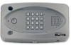
... of the unit. Postal Plug 1 3 4 AUG 10, 2005 WELCOME 12 10 9 8 5 7 6 2 13 11 Page 1 Status LED: Solid Red (EL25 idle power, doors are for a door is unlocked). Microphone 5. Call Button: Press to programmed volume setting when transaction complete. 8. Solid Green (Granted access for a...of Keypad. 11. Up/Down Key: Serves no function on this unit. 9. Lights: Top and Bottom of Keypad. 11. CCTV Camera: Optional 2. Blinking Red (Strikes and Out for a door); Call a resident using the directory codes. 7. plays responses to communicate programming or function...
... of the unit. Postal Plug 1 3 4 AUG 10, 2005 WELCOME 12 10 9 8 5 7 6 2 13 11 Page 1 Status LED: Solid Red (EL25 idle power, doors are for a door is unlocked). Microphone 5. Call Button: Press to programmed volume setting when transaction complete. 8. Solid Green (Granted access for a...of Keypad. 11. Up/Down Key: Serves no function on this unit. 9. Lights: Top and Bottom of Keypad. 11. CCTV Camera: Optional 2. Blinking Red (Strikes and Out for a door); Call a resident using the directory codes. 7. plays responses to communicate programming or function...

EL25-KEYPAD PROGRAMMING Manual
Page 12
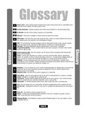
Introduction Introduction Relay 3 - It will also open the gate automatically for exiting cars. Unlocks Pedestrian Gate Card Reader (Pedestrian Gate) EL Model System with an access code or by remote control. Turns on . Opens Vehicular Gate Gate Operator (Vehicular Gate) Relay 2 - Single Family Residence (NPB) Example The unit can operate the vehicular gate with optional CCTV Camera is always on Light It will allow Pedestrians entry with an Access Card. Page 11 Car Exit Sensor Relay 1 -
Introduction Introduction Relay 3 - It will also open the gate automatically for exiting cars. Unlocks Pedestrian Gate Card Reader (Pedestrian Gate) EL Model System with an access code or by remote control. Turns on . Opens Vehicular Gate Gate Operator (Vehicular Gate) Relay 2 - Single Family Residence (NPB) Example The unit can operate the vehicular gate with optional CCTV Camera is always on Light It will allow Pedestrians entry with an Access Card. Page 11 Car Exit Sensor Relay 1 -

EL25-KEYPAD PROGRAMMING Manual
Page 14
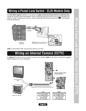
... board(s) Device 0 (Default Internal Keypad) Device 1 Device 2 Device 3 Device 4 Relay 1 Relay 2 Relay 3 Relay 4 Relay Connections Autocall Yes Device No Postal Yes Lock No CCTV Yes Camera No Page 13 Write down your dealer/installer for more information. If you're unsure of your setup, consult your configuration. Your System Layout How...
... board(s) Device 0 (Default Internal Keypad) Device 1 Device 2 Device 3 Device 4 Relay 1 Relay 2 Relay 3 Relay 4 Relay Connections Autocall Yes Device No Postal Yes Lock No CCTV Yes Camera No Page 13 Write down your dealer/installer for more information. If you're unsure of your setup, consult your configuration. Your System Layout How...

EL25-KEYPAD PROGRAMMING Manual
Page 23
...identify the External Access Control Devices wired to it . The Internal Keypad is opened without a valid access code, a door is always on a camera wired to activate other programming. A relay is a device that reacts to an electric current to a closed circuit television (CCTV). The 5 Modes...Door Number 1. Page 22 Once identified, the unit will activate another device such as a siren, when 3 conditions occur. CCTV Relay: The camera is wired to behave." SetUP "Your Settings" SetUP "Your Settings" Setup External Access Control Devices The unit must know what a "Door" ...
...identify the External Access Control Devices wired to it . The Internal Keypad is opened without a valid access code, a door is always on a camera wired to activate other programming. A relay is a device that reacts to an electric current to a closed circuit television (CCTV). The 5 Modes...Door Number 1. Page 22 Once identified, the unit will activate another device such as a siren, when 3 conditions occur. CCTV Relay: The camera is wired to behave." SetUP "Your Settings" SetUP "Your Settings" Setup External Access Control Devices The unit must know what a "Door" ...

EL25-KEYPAD PROGRAMMING Manual
Page 24
..., CCTV, etc.). The Relay Mode determines what the relay will define the amount of time a door cycles (unlocks, then relocks) or how long the CCTV camera remains on a CCTV, etc.). Factory Setting: All Relays are Set at 10 seconds. 1 Press Then 2 Enter the Relay Number (1-4). Then (#) Important: 1-3 must be performed for...
..., CCTV, etc.). The Relay Mode determines what the relay will define the amount of time a door cycles (unlocks, then relocks) or how long the CCTV camera remains on a CCTV, etc.). Factory Setting: All Relays are Set at 10 seconds. 1 Press Then 2 Enter the Relay Number (1-4). Then (#) Important: 1-3 must be performed for...

EL25-KEYPAD PROGRAMMING Manual
Page 26
...Main Keypad (REX) Exit Request Front Door 1 Strike Unlocks Door Door 1 2 Shunt Bypasses/Signals Alarm 3 Alarm Sounds a Siren 4 CCTV Activates Camera 10 sec. 40 sec. 10 sec. 10 sec. Wiegand Card Reader Transmitter Buttons Back Door Gate Operator Door 2 3 Strike Door 3 4 Strike...Lock Security Light Front Door Door 1 1 Strike Unlocks Door 2 Control Turns on Security Light 3 Strike Unlocks Pedestrian Gate 4 CCTV Activates Camera 10 sec. 10 sec. 10 sec. 10 sec. Sample: The System Controlling Multi-Resident Apartment (Page 12 for Illustration) Device Location ...
...Main Keypad (REX) Exit Request Front Door 1 Strike Unlocks Door Door 1 2 Shunt Bypasses/Signals Alarm 3 Alarm Sounds a Siren 4 CCTV Activates Camera 10 sec. 40 sec. 10 sec. 10 sec. Wiegand Card Reader Transmitter Buttons Back Door Gate Operator Door 2 3 Strike Door 3 4 Strike...Lock Security Light Front Door Door 1 1 Strike Unlocks Door 2 Control Turns on Security Light 3 Strike Unlocks Pedestrian Gate 4 CCTV Activates Camera 10 sec. 10 sec. 10 sec. 10 sec. Sample: The System Controlling Multi-Resident Apartment (Page 12 for Illustration) Device Location ...

EL25-KEYPAD PROGRAMMING Manual
Page 27
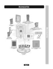
... Card Reader (Back Door) Relay 3 - Strike Mode Unlocks Door for 60 sec. Relay 2 - Relay 4 - Strike Mode Opens Gate for 10 sec. CCTV Mode Activates External Camera or Recorder (not system's camera) Relay 1 - Relay 1 -
... Card Reader (Back Door) Relay 3 - Strike Mode Unlocks Door for 60 sec. Relay 2 - Relay 4 - Strike Mode Opens Gate for 10 sec. CCTV Mode Activates External Camera or Recorder (not system's camera) Relay 1 - Relay 1 -

EL25-KEYPAD PROGRAMMING Manual
Page 67
... Stat Number" is the "Door Number" the door sensor is held open too long or forced open. OR • A Door Number can activate an alarm, camera or other relay controlled device (see Configure the Alarm Features on pages 54 and 55 for more specific relays assigned to "Door Stat 4" activates, Your...
... Stat Number" is the "Door Number" the door sensor is held open too long or forced open. OR • A Door Number can activate an alarm, camera or other relay controlled device (see Configure the Alarm Features on pages 54 and 55 for more specific relays assigned to "Door Stat 4" activates, Your...
EL25-KEYPAD PROGRAMMING Manual
Page 77
Personal Identification Number predefined for example, to lock or unlock a door/gate, shunt (i.e., re-route) alarm contacts, signal an alarm, or turn on a camera that transmits its images to an electric current by activating other compatible devices. Programming Number - A device that is an RF receiver that responds to a closed ...
Personal Identification Number predefined for example, to lock or unlock a door/gate, shunt (i.e., re-route) alarm contacts, signal an alarm, or turn on a camera that transmits its images to an electric current by activating other compatible devices. Programming Number - A device that is an RF receiver that responds to a closed ...

EL25 - INSTALLATION Manual
Page 3
Table of Contents Mounting the Unit Dimensions EL25 Installation Rotating the Keypad for Vertical Mounting Unlocking/Locking EL2000 EL2000 Installation Wire Type Wire Connections to Unit (Factory Settings for Relays) Wire Specs and .../PIR/REX Wiring a Door Sensing Device Wiring the AutoCall Feature Wiring a Radio Frequency Module Wiegand Card Reader / Keypad Wiring a Postal Lock Switch Wiring an Internal Camera (CCTV) Power Wiring Power to the Unit Powering up and Checking the LEDs Troubleshooting Repair Parts "Your" System Diagram and Wiring Configuration Repair Parts "Your...
Table of Contents Mounting the Unit Dimensions EL25 Installation Rotating the Keypad for Vertical Mounting Unlocking/Locking EL2000 EL2000 Installation Wire Type Wire Connections to Unit (Factory Settings for Relays) Wire Specs and .../PIR/REX Wiring a Door Sensing Device Wiring the AutoCall Feature Wiring a Radio Frequency Module Wiegand Card Reader / Keypad Wiring a Postal Lock Switch Wiring an Internal Camera (CCTV) Power Wiring Power to the Unit Powering up and Checking the LEDs Troubleshooting Repair Parts "Your" System Diagram and Wiring Configuration Repair Parts "Your...

EL25 - INSTALLATION Manual
Page 9
... 2-Conductor 18-24 AWG Shielded 5000 feet* 9-14 15 15 16 16 17 17 500 feet 18 500 feet 18 100 feet 18 19 CCTV Camera (Optional) Single Conductor RG-59u Coaxial 1000 feet (Monitor with a .25 volt 19 p-p composite signal sensitivity) NOTE: Use metal conduit - Wires run Telco Wires and...
... 2-Conductor 18-24 AWG Shielded 5000 feet* 9-14 15 15 16 16 17 17 500 feet 18 500 feet 18 100 feet 18 19 CCTV Camera (Optional) Single Conductor RG-59u Coaxial 1000 feet (Monitor with a .25 volt 19 p-p composite signal sensitivity) NOTE: Use metal conduit - Wires run Telco Wires and...

EL25 - INSTALLATION Manual
Page 19
... a Door Sensing Device The units can be connected to any device that is activated (any of the relays (not set as a siren, light or CCTV camera. • Main use is closed. For example, if a door is pried open or is held open after its relay deactivates, the unit will call the...
... a Door Sensing Device The units can be connected to any device that is activated (any of the relays (not set as a siren, light or CCTV camera. • Main use is closed. For example, if a door is pried open or is held open after its relay deactivates, the unit will call the...
EL25 - INSTALLATION Manual
Page 21
...One wire per hole. NOTE: In the EL2000 models, the postal lock switch is pre-wired. Wiring a Postal Lock Switch / Internal Camera (CCTV) Wiring a Postal Lock Switch - J7 J6 POSTAL J3 In N.C. Common Use 18-24 AWG AUTO J5 J2 Switch J1 POWER ... to instructions supplied with programming number 69 , in the Keypad Programming Manual). Refer to a controlled area. Wiring an Internal Camera [CCTV] An Optional CCTV (Close Circuit Television) camera can be installed inside the unit. EL25 Models Only The Post Office requires installation of the four relays (Configurable with the...
...One wire per hole. NOTE: In the EL2000 models, the postal lock switch is pre-wired. Wiring a Postal Lock Switch / Internal Camera (CCTV) Wiring a Postal Lock Switch - J7 J6 POSTAL J3 In N.C. Common Use 18-24 AWG AUTO J5 J2 Switch J1 POWER ... to instructions supplied with programming number 69 , in the Keypad Programming Manual). Refer to a controlled area. Wiring an Internal Camera [CCTV] An Optional CCTV (Close Circuit Television) camera can be installed inside the unit. EL25 Models Only The Post Office requires installation of the four relays (Configurable with the...

EL25 - INSTALLATION Manual
Page 25
... please supply the following information: Description and Model Number Part Description 1 Silver Cover Nickel Cover Mist Gray Cover 2 Lens Black, Camera 3 Lens Clear, Camera 4 Actuator, Call Button, Silver Actuator, Call Button, Nickel Actuator, Call Button, Mist Gray 5 E-Ring, Call Button 6 Spring..., Call Button 7 Gasket, Back 8 Assembly Lock EL25 Focus 9 Key 10 Assembly, Speaker EL25 Model Number Part Description 93D341 93D341-1 93D341-2 108B81 108B81...
... please supply the following information: Description and Model Number Part Description 1 Silver Cover Nickel Cover Mist Gray Cover 2 Lens Black, Camera 3 Lens Clear, Camera 4 Actuator, Call Button, Silver Actuator, Call Button, Nickel Actuator, Call Button, Mist Gray 5 E-Ring, Call Button 6 Spring..., Call Button 7 Gasket, Back 8 Assembly Lock EL25 Focus 9 Key 10 Assembly, Speaker EL25 Model Number Part Description 93D341 93D341-1 93D341-2 108B81 108B81...

EL25 - INSTALLATION Manual
Page 26
... 16 Button 17 Gasket, Keypad 18 Assembly, Mike Cable EL Series 19 Assembly, Entry LED Board 20 Assembly, Keypad Light Board 21 Lens Black, Camera Lens Clear, Camera 22 Gasket and Display Window (Clear) Gasket and Display Window (Black) 23 Faceplate Assembly Black (No Window) Faceplate Assembly Gray (No Window) Faceplate Assembly...
... 16 Button 17 Gasket, Keypad 18 Assembly, Mike Cable EL Series 19 Assembly, Entry LED Board 20 Assembly, Keypad Light Board 21 Lens Black, Camera Lens Clear, Camera 22 Gasket and Display Window (Clear) Gasket and Display Window (Black) 23 Faceplate Assembly Black (No Window) Faceplate Assembly Gray (No Window) Faceplate Assembly...

EL25 - INSTALLATION Manual
Page 28
... 2 Connection Door 4 Connection Door Sensor and/or Exit Device Door Sensor and/or Exit Device Postal Yes Lock No AutoCall Yes Device No CCTV Yes Camera No Dealer / Installer Page 26
... 2 Connection Door 4 Connection Door Sensor and/or Exit Device Door Sensor and/or Exit Device Postal Yes Lock No AutoCall Yes Device No CCTV Yes Camera No Dealer / Installer Page 26
EL25 - INSTALLATION Manual
Page 29
... and Unit Type 2 SEtnatteer/PCroouvn. Accessories Accessories Wiegand Module Kit WOMODKT Directory Insert ELDI EL25 Camera Kits EL25BWCAMKT (Black & White Camera) EL25DVRCAMKT (Low Lux DVR Color Camera) EL25CAMKT (Color Camera) EL2000 Camera Kits EL2000BWCAMKT (Black & White Camera) EL2000DVRCAMKT (Low Lux DVR Color Camera) EL2000CAMKT (Color Camera) RF Module Kit RFMODKT (390 MHz) RFMODKT3 (315 MHz) 123 456 789 *0# Wiegand...
... and Unit Type 2 SEtnatteer/PCroouvn. Accessories Accessories Wiegand Module Kit WOMODKT Directory Insert ELDI EL25 Camera Kits EL25BWCAMKT (Black & White Camera) EL25DVRCAMKT (Low Lux DVR Color Camera) EL25CAMKT (Color Camera) EL2000 Camera Kits EL2000BWCAMKT (Black & White Camera) EL2000DVRCAMKT (Low Lux DVR Color Camera) EL2000CAMKT (Color Camera) RF Module Kit RFMODKT (390 MHz) RFMODKT3 (315 MHz) 123 456 789 *0# Wiegand...
EL25 - QUICK START GUIDE Manual
Page 1
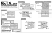
...Relay Type Relay Activation Time 1 Vehicle Gate Strike 2 Vehicle Light Control 2 Seconds 30 Seconds 2 3 Pedestrian Gate Strike 10 Seconds 4 Video Camera CCTV 60 Seconds 2 Set Relay Groups: Relay Group Name Auto Sensor Group Vehicle Gate Group Pedestrian Group Vehicle Gate X Vehicle Light X X Pedestrian... Video Gate Camera X X 1 Rename "Door 1" to "Gate Operator" 1 2 2 Select "Vehicle Gate Group" from the drop-down menu 3 Rename "Door ...
...Relay Type Relay Activation Time 1 Vehicle Gate Strike 2 Vehicle Light Control 2 Seconds 30 Seconds 2 3 Pedestrian Gate Strike 10 Seconds 4 Video Camera CCTV 60 Seconds 2 Set Relay Groups: Relay Group Name Auto Sensor Group Vehicle Gate Group Pedestrian Group Vehicle Gate X Vehicle Light X X Pedestrian... Video Gate Camera X X 1 Rename "Door 1" to "Gate Operator" 1 2 2 Select "Vehicle Gate Group" from the drop-down menu 3 Rename "Door ...

EL25 - QUICK START KEYPAD PROGRAMMING Manual
Page 12
...enters a valid access code. A door is opened with a valid access code. Then the light would then turn on a camera wired to a closed circuit television (CCTV). Allowing the EL25 to lock or unlock a door/gate, shunt (bypass) alarm contacts, signal an alarm, or turn on an entry light ...works with a system like Alarms, CCTV, etc. A camera can be programmed to 5 different modes. Alarm Relay: The Alarm Relay will trigger the alarm relay. EL25 SetUp "Your Settings" EL25 SetUp "Your Settings" Setup External Access Control Devices The EL25 must know what a "Door" Number is and what it...
...enters a valid access code. A door is opened with a valid access code. Then the light would then turn on a camera wired to a closed circuit television (CCTV). Allowing the EL25 to lock or unlock a door/gate, shunt (bypass) alarm contacts, signal an alarm, or turn on an entry light ...works with a system like Alarms, CCTV, etc. A camera can be programmed to 5 different modes. Alarm Relay: The Alarm Relay will trigger the alarm relay. EL25 SetUp "Your Settings" EL25 SetUp "Your Settings" Setup External Access Control Devices The EL25 must know what a "Door" Number is and what it...

EL25 - QUICK START KEYPAD PROGRAMMING Manual
Page 14
... Door 2 Activates Relay 2; Factory Setting: All Relays are Set at 10 seconds 1 Press Then 2 Enter the Relay Number (1-4). activates system's optional camera. 1 = Strike - Then (#) performed for "30" seconds. Step 2 Set Each "Relay Mode" to the unit. 3 Enter Relay Mode ...Important: A1llthroughe3psmust be set at "1 - Then (#) 0 = Not Used 3 = CCTV - Example: 1 2 3 Assigns Relay "2" as a Shunt Relay EL25 SetUp "Your Settings" EL25 SetUp "Your Settings" Step 3 Set Each Relay's "Activation Time": 66 This is entered (open a door, turn on an alarm, turn on a light...
... Door 2 Activates Relay 2; Factory Setting: All Relays are Set at 10 seconds 1 Press Then 2 Enter the Relay Number (1-4). activates system's optional camera. 1 = Strike - Then (#) performed for "30" seconds. Step 2 Set Each "Relay Mode" to the unit. 3 Enter Relay Mode ...Important: A1llthroughe3psmust be set at "1 - Then (#) 0 = Not Used 3 = CCTV - Example: 1 2 3 Assigns Relay "2" as a Shunt Relay EL25 SetUp "Your Settings" EL25 SetUp "Your Settings" Step 3 Set Each Relay's "Activation Time": 66 This is entered (open a door, turn on an alarm, turn on a light...