
CSL24V User Manual
Page 7
...-Hour Battery, 12 Vdc, includes 33AH harness. Do not mix 7AH and 33AH batteries within a gate operator. Models GC824 (115 Vac) and CC824-12 (12/24 Vac/dc) MAGNETIC GATE LOCK Outdoor magnetic lock, transformer, junction box, mounting plate and hardware. Not for each gate operator. Must be mounted onto a gate...
...-Hour Battery, 12 Vdc, includes 33AH harness. Do not mix 7AH and 33AH batteries within a gate operator. Models GC824 (115 Vac) and CC824-12 (12/24 Vac/dc) MAGNETIC GATE LOCK Outdoor magnetic lock, transformer, junction box, mounting plate and hardware. Not for each gate operator. Must be mounted onto a gate...
CSW24V Quick Start Guide Manual
Page 1
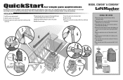
... the vent plug on Front Cover Tabs on Rear Cover 5/16-18 Screw 4 Concrete Anchors 1/2" x 3 1/2" 2 6 inches (check local and national codes) 1 24 inches 28 inches 9 Slots on Chassis 5/16-18 Hex Bolts and Washers Groove on both sides of the rear cover to the chassis with two...this position. 6 Weld the short arm section. 7 Secure the operator arm to the installation manual for single gate applications MODEL CSW24V™ & CSW24VH™ This QuickStart is installed and operated properly. QuickStart for complete information regarding installation, testing, and programming.
... the vent plug on Front Cover Tabs on Rear Cover 5/16-18 Screw 4 Concrete Anchors 1/2" x 3 1/2" 2 6 inches (check local and national codes) 1 24 inches 28 inches 9 Slots on Chassis 5/16-18 Hex Bolts and Washers Groove on both sides of the rear cover to the chassis with two...this position. 6 Weld the short arm section. 7 Secure the operator arm to the installation manual for single gate applications MODEL CSW24V™ & CSW24VH™ This QuickStart is installed and operated properly. QuickStart for complete information regarding installation, testing, and programming.
CSW24V Installation Manual
Page 3
... the Entrapment Protection Devices 17 Earth Ground Rod 17 Power Wiring 18-19 Dual Gates Only 20-22 Connect Batteries 22-23 ADJUSTMENT 24-25 Limit and Force Adjustment 24-25 Obstruction Test 25 MAINTENANCE 35 Maintenance Chart 35 Batteries 35 TROUBLESHOOTING 36-41 Control Board LEDs 36-37 Troubleshooting Chart 38...
... the Entrapment Protection Devices 17 Earth Ground Rod 17 Power Wiring 18-19 Dual Gates Only 20-22 Connect Batteries 22-23 ADJUSTMENT 24-25 Limit and Force Adjustment 24-25 Obstruction Test 25 MAINTENANCE 35 Maintenance Chart 35 Batteries 35 TROUBLESHOOTING 36-41 Control Board LEDs 36-37 Troubleshooting Chart 38...
CSW24V Installation Manual
Page 10
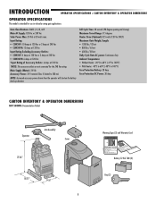
...: 24 V nominal Class II limited to 140°F) Fuse Protection Battery: 30 Amp Fuse Protection DC Power: 30 Amp CARTON INVENTORY & OPERATOR DIMENSIONS NOT SHOWN: Documentation Packet Operator Arm Assembly Cover 27.66" 18.77" 14.6" 8 Warning Signs (2) and Warranty Card Battery 12 Vdc 7AH (2) Key (2) Input Rating: • CSW24V: ... Amps at 120 Vac or 2 Amps at 240 Vac • CSW24VH: 12 Amps at 120 Vac Input Rating Excluding Accessory Outlets: • CSW24V: 4 Amps at 120 Vac or 2 Amps at 240 Vac • CSW24VH: 6 Amps at 120 Vac *Input Rating of Accessory Outlets: 6 Amps at 120 Vac *...
...: 24 V nominal Class II limited to 140°F) Fuse Protection Battery: 30 Amp Fuse Protection DC Power: 30 Amp CARTON INVENTORY & OPERATOR DIMENSIONS NOT SHOWN: Documentation Packet Operator Arm Assembly Cover 27.66" 18.77" 14.6" 8 Warning Signs (2) and Warranty Card Battery 12 Vdc 7AH (2) Key (2) Input Rating: • CSW24V: ... Amps at 120 Vac or 2 Amps at 240 Vac • CSW24VH: 12 Amps at 120 Vac Input Rating Excluding Accessory Outlets: • CSW24V: 4 Amps at 120 Vac or 2 Amps at 240 Vac • CSW24VH: 6 Amps at 120 Vac *Input Rating of Accessory Outlets: 6 Amps at 120 Vac *...
CSW24V Installation Manual
Page 11
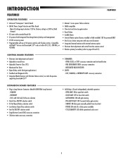
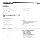
... (factory setting) or 240 Vac (field change) • DC motor with extended brush life • AC powered with integrated Evercharge battery backup and management • 24 Vdc accessory power • Programmable with external antenna option • Electronic limit adjustment and control from close limit switch - FIRE DEPARTMENT OPEN: accessory connection - SHADOW...
... (factory setting) or 240 Vac (field change) • DC motor with extended brush life • AC powered with integrated Evercharge battery backup and management • 24 Vdc accessory power • Programmable with external antenna option • Electronic limit adjustment and control from close limit switch - FIRE DEPARTMENT OPEN: accessory connection - SHADOW...

CSW24V Installation Manual
Page 14
... the frost line. CONDUIT LOCATION 5.5" 4.5" 1" 6.5" 4" 1.5" (Conduit) 3" 10" 20" 28" MOUNTING FOOTPRINT 13.6" 12.2" 6.1" 2.49" 14" 15" (Pad) 24" 14.82" (cover mounting distance) TOP VIEW OF OPERATOR AND GATE 1 Gate Hinge 1/4 1/4 1/4 A 2 B 90° minimum of 9 inches. NOTE: When lifting...A to accessories). 12 Post Mount 6" Above Ground 2 Below the frost line. Check all national and local codes. 1 28" 24" 3 4 Concrete Anchors 1/2" x 3 1/2" 24" This is a recommended guide for positioning the concrete pad: 1 Measure 1/4 the length of the gate from the center of the...
... the frost line. CONDUIT LOCATION 5.5" 4.5" 1" 6.5" 4" 1.5" (Conduit) 3" 10" 20" 28" MOUNTING FOOTPRINT 13.6" 12.2" 6.1" 2.49" 14" 15" (Pad) 24" 14.82" (cover mounting distance) TOP VIEW OF OPERATOR AND GATE 1 Gate Hinge 1/4 1/4 1/4 A 2 B 90° minimum of 9 inches. NOTE: When lifting...A to accessories). 12 Post Mount 6" Above Ground 2 Below the frost line. Check all national and local codes. 1 28" 24" 3 4 Concrete Anchors 1/2" x 3 1/2" 24" This is a recommended guide for positioning the concrete pad: 1 Measure 1/4 the length of the gate from the center of the...

CSW24V Installation Manual
Page 16
... run the operator until instructed. CONDUIT LOCATION 5.5" 4.5" 1" 6.5" 4" 1.5" (Conduit) 3" 10" 20" 28" MOUNTING FOOTPRINT 13.6" 12.2" 6.1" 2.49" 14" 15" (Pad) 24" 14.82" (cover mounting distance) 14 3 4 Concrete Anchors 1/2" x 3 1/2" 1 28" 24" Post Mount 2 24" 6" Above Ground Below the frost line. The concrete pad should be 6 inches above the ground and deeper than the frost...
... run the operator until instructed. CONDUIT LOCATION 5.5" 4.5" 1" 6.5" 4" 1.5" (Conduit) 3" 10" 20" 28" MOUNTING FOOTPRINT 13.6" 12.2" 6.1" 2.49" 14" 15" (Pad) 24" 14.82" (cover mounting distance) 14 3 4 Concrete Anchors 1/2" x 3 1/2" 1 28" 24" Post Mount 2 24" 6" Above Ground Below the frost line. The concrete pad should be 6 inches above the ground and deeper than the frost...

CSW24V Installation Manual
Page 26
... . 4 Press and hold one of the MOVE GATE buttons to move the gate to open or close . OFF NORMAL MODE Limits are set . CLOSE limit 24 2 PRESS & RELEASE TO BEGIN 3 TO BEGIN LIMIT RESET ALARM MOVE GATE PRESS & RELEASE TO BEGIN LIMIT SETUP 5 4 SET OPEN SET CLOSE STATUS: INPUT POWER OPEN...
... . 4 Press and hold one of the MOVE GATE buttons to move the gate to open or close . OFF NORMAL MODE Limits are set . CLOSE limit 24 2 PRESS & RELEASE TO BEGIN 3 TO BEGIN LIMIT RESET ALARM MOVE GATE PRESS & RELEASE TO BEGIN LIMIT SETUP 5 4 SET OPEN SET CLOSE STATUS: INPUT POWER OPEN...
CSW24V Installation Manual
Page 32
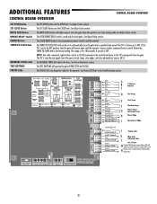
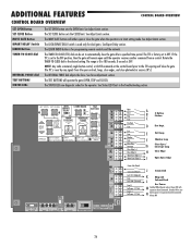
... Close Edge (+) Close Edge (-) Open Eyes/Edge (+) Open Eyes/Edge (-) Comm Link Data A Comm Link Data B Lock N.C. (Maglock) Com Lock N.O. (Solenoid) Com (-) AccPower +24 Vdc Com (-) AccPower +24 Vdc A B C 3 Button Station D Fire Dept. The MOVE GATE buttons will remain open controls, loops, close edges, and close the gate. The REVERSAL FORCE dial...
... Close Edge (+) Close Edge (-) Open Eyes/Edge (+) Open Eyes/Edge (-) Comm Link Data A Comm Link Data B Lock N.C. (Maglock) Com Lock N.O. (Solenoid) Com (-) AccPower +24 Vdc Com (-) AccPower +24 Vdc A B C 3 Button Station D Fire Dept. The MOVE GATE buttons will remain open controls, loops, close edges, and close the gate. The REVERSAL FORCE dial...

CSW24V Installation Manual
Page 33
...condition) If maintained, pauses Timer-to open gate (within line-of the gate. - N Accessory Power Out Un-switched, (2 terminals) 24 Vdc voltage out to motor activation and during motor run . Stops and reverses a closing gate and holds open an open gate. closed (N.C.)...putting out a pulse train when unblocked. Overrides Open and Close commands (within line-of -sight). M Accessory Power Out Switched, (2 terminals) 24 Vdc voltage out to -Close at open (maintained switch does not override external safeties and does not reset alarm condition) If maintained, pauses ...
...condition) If maintained, pauses Timer-to open gate (within line-of the gate. - N Accessory Power Out Un-switched, (2 terminals) 24 Vdc voltage out to motor activation and during motor run . Stops and reverses a closing gate and holds open an open gate. closed (N.C.)...putting out a pulse train when unblocked. Overrides Open and Close commands (within line-of -sight). M Accessory Power Out Switched, (2 terminals) 24 Vdc voltage out to -Close at open (maintained switch does not override external safeties and does not reset alarm condition) If maintained, pauses ...

CSW24V Installation Manual
Page 44
... Black White White Purple Black Red Black Red Identification Resistor Piezo Alarm To Pin 2 To Pin 1 Run Stop/Reset Reset Switch Ferrite EMI Filters 1/2 HP 24 Vdc Motor APS Encoder EXPANSION BOARD 1 N.C. Yellow Blue Black Red For continued protection against fire and electrocution: • DISCONNECT power and battery BEFORE installing or...
... Black White White Purple Black Red Black Red Identification Resistor Piezo Alarm To Pin 2 To Pin 1 Run Stop/Reset Reset Switch Ferrite EMI Filters 1/2 HP 24 Vdc Motor APS Encoder EXPANSION BOARD 1 N.C. Yellow Blue Black Red For continued protection against fire and electrocution: • DISCONNECT power and battery BEFORE installing or...
CSW24V Installation Manual
Page 45
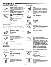
...mounted onto a gate or post. Models GC824 (115 Vac) and GC824-12 (12/24 Vac/dc) WIRELESS ACCESS CONTROL RECEIVER Access control receiver for all MG020 type edges. Single...junction box, mounting plate and hardware. Ideal for extended periods of LiftMaster remote controls to satisfy your authorized LiftMaster dealer for additional details and options. 3-BUTTON REMOTE CONTROL The 3-button...gate is open the gate. Model 877MAX MISCELLANEOUS POST-MOUNTING PLATE For post-mounting model CSW24V commercial swing operator (also CSW200 commercial swing operator). Models GHTRKITRSW (for Swing operator,...
...mounted onto a gate or post. Models GC824 (115 Vac) and GC824-12 (12/24 Vac/dc) WIRELESS ACCESS CONTROL RECEIVER Access control receiver for all MG020 type edges. Single...junction box, mounting plate and hardware. Ideal for extended periods of LiftMaster remote controls to satisfy your authorized LiftMaster dealer for additional details and options. 3-BUTTON REMOTE CONTROL The 3-button...gate is open the gate. Model 877MAX MISCELLANEOUS POST-MOUNTING PLATE For post-mounting model CSW24V commercial swing operator (also CSW200 commercial swing operator). Models GHTRKITRSW (for Swing operator,...

CSW24V Installation Manual
Page 46
... 15 K1D6597-1CC 16 K1D6686CC 17 K76-34728 18 K77-36541 19 K76-36398 20 K77-36542 21 K180A0357 22 K94-35152 23 K75-36260 24 Q118 25 K13-34729 26 Q061 27 Q059 28 Q060 29 Q104 DESCRIPTION Cludge Cover Operator Cover with labels, keys, and lock assembly Chassis... with mounting hardware Bridge Rectifier Main Board with heat sink Expansion Board EMI Board with 120V receptacles and AC power switch Antenna Motor, 1/2 HP, 24 Vdc Electrical Box with junction box Reset Switch Alarm with harness Lock and Keys Keys Dust Guard Output Shaft Cludge Arm Clamp and Release Handle...
... 15 K1D6597-1CC 16 K1D6686CC 17 K76-34728 18 K77-36541 19 K76-36398 20 K77-36542 21 K180A0357 22 K94-35152 23 K75-36260 24 Q118 25 K13-34729 26 Q061 27 Q059 28 Q060 29 Q104 DESCRIPTION Cludge Cover Operator Cover with labels, keys, and lock assembly Chassis... with mounting hardware Bridge Rectifier Main Board with heat sink Expansion Board EMI Board with 120V receptacles and AC power switch Antenna Motor, 1/2 HP, 24 Vdc Electrical Box with junction box Reset Switch Alarm with harness Lock and Keys Keys Dust Guard Output Shaft Cludge Arm Clamp and Release Handle...
CSW24V Manual
Page 3
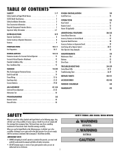
...-20 ADJUSTMENT 21-22 Limit and Force Adjustment 21-22 Obstruction Test 22 PROGRAMMING 23 Remote Controls 23 Erase All Codes 23 FINISH INSTALLATION 24 Install the Cover 24 OPERATION 25 Reset Switch 25 Remote Control 25 Heater (If Applicable 25 ADDITIONAL FEATURES 26-32 Control Board Overview 26 Accessory Features on...
...-20 ADJUSTMENT 21-22 Limit and Force Adjustment 21-22 Obstruction Test 22 PROGRAMMING 23 Remote Controls 23 Erase All Codes 23 FINISH INSTALLATION 24 Install the Cover 24 OPERATION 25 Reset Switch 25 Remote Control 25 Heater (If Applicable 25 ADDITIONAL FEATURES 26-32 Control Board Overview 26 Accessory Features on...

CSW24V Manual
Page 10
... will shorten the battery back-up duration. Heater Draw (Optional): 325 watts (120 Vac ONLY) Maximum Gate Weight: 1500 lbs. Main Supply (Motor): 24 Vdc Accessory Power: 24 V nominal Class II limited to 140°F) Fuse Protection Battery: 30 Amp Fuse Protection DC Power: 30 Amp CARTON INVENTORY & OPERATOR DIMENSIONS NOT SHOWN... intended for use in vehicular slide gate applications: Gate Classifications: CLASS I, II, III, & IV Main AC Supply: 120 Vac or 240 Vac Solar Power Max: 24 Vdc at 120 Vac *NOTE: The accessory outlets are not connected for the 240 Vac rating.
... will shorten the battery back-up duration. Heater Draw (Optional): 325 watts (120 Vac ONLY) Maximum Gate Weight: 1500 lbs. Main Supply (Motor): 24 Vdc Accessory Power: 24 V nominal Class II limited to 140°F) Fuse Protection Battery: 30 Amp Fuse Protection DC Power: 30 Amp CARTON INVENTORY & OPERATOR DIMENSIONS NOT SHOWN... intended for use in vehicular slide gate applications: Gate Classifications: CLASS I, II, III, & IV Main AC Supply: 120 Vac or 240 Vac Solar Power Max: 24 Vdc at 120 Vac *NOTE: The accessory outlets are not connected for the 240 Vac rating.
CSW24V Manual
Page 11
... (factory setting) or 240 Vac (field change) • DC motor with extended brush life • AC powered with integrated Evercharge battery backup and management • 24 Vdc accessory power • Programmable with external antenna option • Electronic limit adjustment and control from close limit switch - INTEGRATED RADIO RECEIVER • LOOPS: - TAMPER...
... (factory setting) or 240 Vac (field change) • DC motor with extended brush life • AC powered with integrated Evercharge battery backup and management • 24 Vdc accessory power • Programmable with external antenna option • Electronic limit adjustment and control from close limit switch - INTEGRATED RADIO RECEIVER • LOOPS: - TAMPER...

CSW24V Manual
Page 14
... 3 Attach the operator to the concrete pad with appropriate fasteners. STANDARD INSTALLATION 4"(10 cm) 1 26" (66 cm) 2 24" (61 cm) REAR INSTALLATION 1 2 CONCRETE PAD AND OPERATOR ATTACHMENT Check the national and local building codes before installation. 1 ... 11.9" 10.3" 2.85" 4 Concrete Anchors 1/2" x 3 1/2" 2 (Conduit) .63" 13" 23" 26" 10.4" 1 14.1" 4-1/2" 8" 15" (Pad) 24" 14.6" 12 24" (61 cm) 4" (10 cm) 26" (66 cm) 24" (61 cm) Post Mount 6" Above Ground Below the frost line. INSTALLATION DETERMINE LOCATION FOR CONCRETE PAD AND OPERATOR + CONCRETE PAD & OPERATOR...
... 3 Attach the operator to the concrete pad with appropriate fasteners. STANDARD INSTALLATION 4"(10 cm) 1 26" (66 cm) 2 24" (61 cm) REAR INSTALLATION 1 2 CONCRETE PAD AND OPERATOR ATTACHMENT Check the national and local building codes before installation. 1 ... 11.9" 10.3" 2.85" 4 Concrete Anchors 1/2" x 3 1/2" 2 (Conduit) .63" 13" 23" 26" 10.4" 1 14.1" 4-1/2" 8" 15" (Pad) 24" 14.6" 12 24" (61 cm) 4" (10 cm) 26" (66 cm) 24" (61 cm) Post Mount 6" Above Ground Below the frost line. INSTALLATION DETERMINE LOCATION FOR CONCRETE PAD AND OPERATOR + CONCRETE PAD & OPERATOR...

CSW24V Manual
Page 26
...-18 hex bolts and washers. 5/16-18 Screw 3 Align the front cover with the back cover, making sure the grooves line up . Factory Default position 24 (back of two pieces: a rear cover and a front cover. FINISH INSTALLATION INSTALL THE COVER INSTALL THE COVER The operator cover consists of front cover) To...
...-18 hex bolts and washers. 5/16-18 Screw 3 Align the front cover with the back cover, making sure the grooves line up . Factory Default position 24 (back of two pieces: a rear cover and a front cover. FINISH INSTALLATION INSTALL THE COVER INSTALL THE COVER The operator cover consists of front cover) To...
CSW24V Manual
Page 28
... Loop Close Eyes/ Interrupt Loop Close Edge Open Eyes/Edge Comm Link Data A Comm Link Data B Lock N.C. (Maglock) Com Lock N.O. (Solenoid) Com (-) AccPower +24 Vdc Com (-) AccPower +24 Vdc J Comm Link K Mag and L Solenoid Lock Acc. If the TTC is for the operator. NOTE: Any radio command, single button control, or CLOSE...
... Loop Close Eyes/ Interrupt Loop Close Edge Open Eyes/Edge Comm Link Data A Comm Link Data B Lock N.C. (Maglock) Com Lock N.O. (Solenoid) Com (-) AccPower +24 Vdc Com (-) AccPower +24 Vdc J Comm Link K Mag and L Solenoid Lock Acc. If the TTC is for the operator. NOTE: Any radio command, single button control, or CLOSE...

CSW24V Manual
Page 29
...edge sensor = normally open . closed (N.C.) output for 2 seconds with obstruction. N Accessory Power Out Un-switched, (2 terminals) 24 Vdc voltage out to save battery power Always on if Expansion Board is off. Hard close (maintained switch overrides external safeties and ...fully with obstruction. H Close Edge (2 terminals) Close Direction Edge Sensor to open limit - M Accessory Power Out Switched, (2 terminals) 24 Vdc voltage out to power accessories, will turn off when motor is connected. stops a moving gate. Pulsed Photoelectric Sensors = monitored device...
...edge sensor = normally open . closed (N.C.) output for 2 seconds with obstruction. N Accessory Power Out Un-switched, (2 terminals) 24 Vdc voltage out to save battery power Always on if Expansion Board is off. Hard close (maintained switch overrides external safeties and ...fully with obstruction. H Close Edge (2 terminals) Close Direction Edge Sensor to open limit - M Accessory Power Out Switched, (2 terminals) 24 Vdc voltage out to power accessories, will turn off when motor is connected. stops a moving gate. Pulsed Photoelectric Sensors = monitored device...

