
CSL24V User Manual
Page 4
...Check for excessive slack and lubricate The following should be checked by an authorized LiftMaster dealer: DESCRIPTION Manual Disconnect Sprockets and Chains Belt and Pulley (Slide Only) Accessories Electrical Chassis Mounting Bolts Operator Batteries TASK Check and test for proper operation ...Inspect all wire connections Check for tightness Inspect for replacement batteries. For best performance, the batteries should be disposed of chain length. 3 Use only LiftMaster part 29-NP712 for wear or damage Replace CHECK AT LEAST ONCE EVERY 6 MONTHS X X 3 YEARS X X X X X X BATTERIES ...
...Check for excessive slack and lubricate The following should be checked by an authorized LiftMaster dealer: DESCRIPTION Manual Disconnect Sprockets and Chains Belt and Pulley (Slide Only) Accessories Electrical Chassis Mounting Bolts Operator Batteries TASK Check and test for proper operation ...Inspect all wire connections Check for tightness Inspect for replacement batteries. For best performance, the batteries should be disposed of chain length. 3 Use only LiftMaster part 29-NP712 for wear or damage Replace CHECK AT LEAST ONCE EVERY 6 MONTHS X X 3 YEARS X X X X X X BATTERIES ...

CSL24V User Manual
Page 5
...can detect an obstacle upon contact and stop the operator. Single-button to control the operator. Includes visor clip. Model 877MAX 4 ACCESSORIES ENTRAPMENT PROTECTION DEVICES PHOTOELECTRIC SENSORS (NON-CONTACT) The photoelectric sensors are compatible with operators manufactured by entering a 4-digit code on ...a specially designed keypad. Model 890MAX KEYLESS ENTRY Enables homeowner to detect an obstacle in the path of LiftMaster remote controls to control the operator. Models AOMRON E3K-R10K4-NR (retro-reflective), RETROAB 60-2728 (retro-reflective), CPS-UN4 ...
...can detect an obstacle upon contact and stop the operator. Single-button to control the operator. Includes visor clip. Model 877MAX 4 ACCESSORIES ENTRAPMENT PROTECTION DEVICES PHOTOELECTRIC SENSORS (NON-CONTACT) The photoelectric sensors are compatible with operators manufactured by entering a 4-digit code on ...a specially designed keypad. Model 890MAX KEYLESS ENTRY Enables homeowner to detect an obstacle in the path of LiftMaster remote controls to control the operator. Models AOMRON E3K-R10K4-NR (retro-reflective), RETROAB 60-2728 (retro-reflective), CPS-UN4 ...

CSL24V User Manual
Page 6
... temperature when outside temperature is below 0°F for optimal 7AH battery location) and G6518SL (replacement heater only) LOOP DETECTOR Low power loop detectors. Model LOOPDETLM 5 ACCESSORIES MISCELLANEOUS POST-MOUNTING PLATE For post-mounting commercial slide/swing operators. Posts not included.
... temperature when outside temperature is below 0°F for optimal 7AH battery location) and G6518SL (replacement heater only) LOOP DETECTOR Low power loop detectors. Model LOOPDETLM 5 ACCESSORIES MISCELLANEOUS POST-MOUNTING PLATE For post-mounting commercial slide/swing operators. Posts not included.

CSL24V User Manual
Page 7
... mounted onto a gate or post. Not for use with operator, reuse existing harnesses) Model A12330SGLPK (upgrade 33 AMP-Hour Battery, 12 Vdc, includes 33AH harness. ACCESSORIES VEHICLE SENSING PROBE The vehicle sensing probe is buried in the ground and can be released in case of emergency. Models GC824 (115 Vac) and...
... mounted onto a gate or post. Not for use with operator, reuse existing harnesses) Model A12330SGLPK (upgrade 33 AMP-Hour Battery, 12 Vdc, includes 33AH harness. ACCESSORIES VEHICLE SENSING PROBE The vehicle sensing probe is buried in the ground and can be released in case of emergency. Models GC824 (115 Vac) and...
CSW24V Installation Manual
Page 3
... Heater (If Applicable 28 ADDITIONAL FEATURES 29-34 Gate Operator Setup Examples 29 Control Board Overview 30 Accessory Features on Control Board 31 Expansion Board Overview 32 Accessory Features on Expansion Board 33 Limit Setup with a Remote Control 34 WIRING 17-23 Wire the Entrapment...MAINTENANCE 35 Maintenance Chart 35 Batteries 35 TROUBLESHOOTING 36-41 Control Board LEDs 36-37 Troubleshooting Chart 38-41 WIRING DIAGRAMS 42 ACCESSORIES 43 REPAIR PARTS 44-45 WARRANTY BACK COVER SAFETY SAFETY SYMBOL AND SIGNAL WORD REVIEW When you see this manual and ...
... Heater (If Applicable 28 ADDITIONAL FEATURES 29-34 Gate Operator Setup Examples 29 Control Board Overview 30 Accessory Features on Control Board 31 Expansion Board Overview 32 Accessory Features on Expansion Board 33 Limit Setup with a Remote Control 34 WIRING 17-23 Wire the Entrapment...MAINTENANCE 35 Maintenance Chart 35 Batteries 35 TROUBLESHOOTING 36-41 Control Board LEDs 36-37 Troubleshooting Chart 38-41 WIRING DIAGRAMS 42 ACCESSORIES 43 REPAIR PARTS 44-45 WARRANTY BACK COVER SAFETY SAFETY SYMBOL AND SIGNAL WORD REVIEW When you see this manual and ...
CSW24V Installation Manual
Page 10
..., & IV Main AC Supply: 120 Vac or 240 Vac Solar Power Max: 24 Vdc at 120 Vac *NOTE: The accessory outlets are not connected for the 240 Vac rating. Input Rating: • CSW24V: 10 Amps at 120 Vac or 2 Amps at 240 Vac • CSW24VH: 12 Amps at 120 Vac Input Rating... Excluding Accessory Outlets: • CSW24V: 4 Amps at 120 Vac or 2 Amps at 240 Vac • CSW24VH: 6 Amps at 120 Vac *Input Rating...
..., & IV Main AC Supply: 120 Vac or 240 Vac Solar Power Max: 24 Vdc at 120 Vac *NOTE: The accessory outlets are not connected for the 240 Vac rating. Input Rating: • CSW24V: 10 Amps at 120 Vac or 2 Amps at 240 Vac • CSW24VH: 12 Amps at 120 Vac Input Rating... Excluding Accessory Outlets: • CSW24V: 4 Amps at 120 Vac or 2 Amps at 240 Vac • CSW24VH: 6 Amps at 120 Vac *Input Rating...
CSW24V Installation Manual
Page 11
...supporting Security✚ 2.0™ • COMMANDS: - CYCLE QUANTITY: LEDs blink operational cycle count 9 OPEN, CLOSE, or STOP: accessory connection and on-board button - EXIT, with AC or Solar power available - OPEN LIMIT: ON at close limit - POWER: ...Low Battery Open/Close selection switch • Anti-Tail ON/OFF selection switch • Single Button Control (SBC) accessory connection • 3-Button station accessory connection • AUX Relays (2) each independently selectable operation: - INTRODUCTION FEATURES OPERATOR FEATURES • Advanced "Centerpiece" ...
...supporting Security✚ 2.0™ • COMMANDS: - CYCLE QUANTITY: LEDs blink operational cycle count 9 OPEN, CLOSE, or STOP: accessory connection and on-board button - EXIT, with AC or Solar power available - OPEN LIMIT: ON at close limit - POWER: ...Low Battery Open/Close selection switch • Anti-Tail ON/OFF selection switch • Single Button Control (SBC) accessory connection • 3-Button station accessory connection • AUX Relays (2) each independently selectable operation: - INTRODUCTION FEATURES OPERATOR FEATURES • Advanced "Centerpiece" ...

CSW24V Installation Manual
Page 14
... the gate hinge. 3 Open the gate 90°. NOTE: An alternative to a concrete pad is tall enough to avoid possible flooding. 3 Secure the operator to accessories). 12 Post Mount 6" Above Ground 2 Below the frost line. CONDUIT LOCATION 5.5" 4.5" 1" 6.5" 4" 1.5" (Conduit) 3" 10" 20" 28" MOUNTING FOOTPRINT 13.6" 12.2" 6.1" 2.49" 14" 15" (Pad) 24" 14...
... the gate hinge. 3 Open the gate 90°. NOTE: An alternative to a concrete pad is tall enough to avoid possible flooding. 3 Secure the operator to accessories). 12 Post Mount 6" Above Ground 2 Below the frost line. CONDUIT LOCATION 5.5" 4.5" 1" 6.5" 4" 1.5" (Conduit) 3" 10" 20" 28" MOUNTING FOOTPRINT 13.6" 12.2" 6.1" 2.49" 14" 15" (Pad) 24" 14...

CSW24V Installation Manual
Page 16
...) 24" 14.82" (cover mounting distance) 14 3 4 Concrete Anchors 1/2" x 3 1/2" 1 28" 24" Post Mount 2 24" 6" Above Ground Below the frost line. Refer to the illustration to accessories). Gate Hinge Center TOP VIEW OF OPERATOR AND GATE Gate Open 90° 26-1/2" Output Shaft Center 9" 28" Handle CONCRETE PAD AND OPERATOR ATTACHMENT Check...
...) 24" 14.82" (cover mounting distance) 14 3 4 Concrete Anchors 1/2" x 3 1/2" 1 28" 24" Post Mount 2 24" 6" Above Ground Below the frost line. Refer to the illustration to accessories). Gate Hinge Center TOP VIEW OF OPERATOR AND GATE Gate Open 90° 26-1/2" Output Shaft Center 9" 28" Handle CONCRETE PAD AND OPERATOR ATTACHMENT Check...

CSW24V Installation Manual
Page 19
... turn on the other operator. RESET ALARM TO ERASE LEARNED MONITORED PHOTOELECTRIC SENSORS 1 Remove the photoelectric sensor wires from the earth ground rod to the "Accessory Features on the Control Board" section on the OPEN EYES/EDGE terminal. NOTE: For dual gate applications repeat the steps above on . 3 Press both SET...
... turn on the other operator. RESET ALARM TO ERASE LEARNED MONITORED PHOTOELECTRIC SENSORS 1 Remove the photoelectric sensor wires from the earth ground rod to the "Accessory Features on the Control Board" section on the OPEN EYES/EDGE terminal. NOTE: For dual gate applications repeat the steps above on . 3 Press both SET...

CSW24V Installation Manual
Page 20
... feet 650 feet 1040 feet 1650 feet 2624 feet POWER WIRING NUMBER OF CYCLES PER DAY Swing Gate Installation (12 ft. 800 lb. The accessory outlet is now set for either 120 Vac or 240 Vac or a solar panel (not provided). For dual gate applications, power will turn ...off AC power to each operator. gate) Accessories Single Gate 7AH Batteries (standard) 33AH Batteries (optional) Solenoid Lock 50 mA 100 mA 300 mA TRANSFORMER POWERED ✔ ✔ ✔ ✔ BATTERY ...
... feet 650 feet 1040 feet 1650 feet 2624 feet POWER WIRING NUMBER OF CYCLES PER DAY Swing Gate Installation (12 ft. 800 lb. The accessory outlet is now set for either 120 Vac or 240 Vac or a solar panel (not provided). For dual gate applications, power will turn ...off AC power to each operator. gate) Accessories Single Gate 7AH Batteries (standard) 33AH Batteries (optional) Solenoid Lock 50 mA 100 mA 300 mA TRANSFORMER POWERED ✔ ✔ ✔ ✔ BATTERY ...

CSW24V Installation Manual
Page 21
...use the expansion board and the wireless dual gate feature. Unplug the wires from the bridge rectifier located on the control board. SEE ACCESSORIES. This is not supported in series and two 7AH batteries are recommended. Solar panels should be two 20W panels in an open ...using a wire nut. Cycle rate may vary from solar chart for best performance to ensure proper operation. We recommend LiftMaster low power draw accessories to minimize power draw, refer to accessory page. 1 Remove the outlet housing from the chassis by removing the screws (2). 2 Remove the electrical box from ...
...use the expansion board and the wireless dual gate feature. Unplug the wires from the bridge rectifier located on the control board. SEE ACCESSORIES. This is not supported in series and two 7AH batteries are recommended. Solar panels should be two 20W panels in an open ...using a wire nut. Cycle rate may vary from solar chart for best performance to ensure proper operation. We recommend LiftMaster low power draw accessories to minimize power draw, refer to accessory page. 1 Remove the outlet housing from the chassis by removing the screws (2). 2 Remove the electrical box from ...

CSW24V Installation Manual
Page 23
... GATES ONLY WIRELESS DUAL GATES Turn on power to the primary operator. 2 Press and release the LEARN RADIO button on the primary operator. All wireless accessories will need to assign this operator as network primary. 5 Press and release the LEARN RADIO button on either operator. The green XMITTER LED will light...
... GATES ONLY WIRELESS DUAL GATES Turn on power to the primary operator. 2 Press and release the LEARN RADIO button on the primary operator. All wireless accessories will need to assign this operator as network primary. 5 Press and release the LEARN RADIO button on either operator. The green XMITTER LED will light...

CSW24V Installation Manual
Page 33
... to -Close at open limit - connects two operators together (primary-secondary wired connection) K Lock Outputs: Maglock (2 terminals, N.C. N Accessory Power Out Un-switched, (2 terminals) 24 Vdc voltage out to -Close at OPEN limit. Hard stop (maintained switch overrides Open and ...opening . and COM) Relay contact output, Normally - L Solenoid Lock & Common (2 terminals, N.O. M Accessory Power Out Switched, (2 terminals) 24 Vdc voltage out to power accessories, will turn off when gate is not in motion to Close Entrapments Input, disregarded during motor run . ...
... to -Close at open limit - connects two operators together (primary-secondary wired connection) K Lock Outputs: Maglock (2 terminals, N.C. N Accessory Power Out Un-switched, (2 terminals) 24 Vdc voltage out to -Close at OPEN limit. Hard stop (maintained switch overrides Open and ...opening . and COM) Relay contact output, Normally - L Solenoid Lock & Common (2 terminals, N.O. M Accessory Power Out Switched, (2 terminals) 24 Vdc voltage out to power accessories, will turn off when gate is not in motion to Close Entrapments Input, disregarded during motor run . ...
CSW24V Installation Manual
Page 34
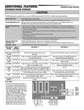
... solar power is present. light). warning light or sounder). ADDITIONAL FEATURES EXPANSION BOARD OVERVIEW EXPANSION BOARD OVERVIEW To AVOID damaging the circuit board, relays or accessories, DO NOT connect more than 42 Vdc (32 Vac) to OPEN, if the EXIT plug-in loop detector detects a fault, then the gate will open...
... solar power is present. light). warning light or sounder). ADDITIONAL FEATURES EXPANSION BOARD OVERVIEW EXPANSION BOARD OVERVIEW To AVOID damaging the circuit board, relays or accessories, DO NOT connect more than 42 Vdc (32 Vac) to OPEN, if the EXIT plug-in loop detector detects a fault, then the gate will open...

CSW24V Installation Manual
Page 35
... loop detector when loop is along side gate. - Pauses Timer-to -Close at Close limit and during gate motion - closed gate. ADDITIONAL FEATURES ACCESSORY FEATURES ON EXPANSION BOARD ACCESSORY FEATURES ON EXPANSION BOARD A Open Input (& common) (3-Button Control Station, 4 terminals total) B Close Input (& common) (3-Button Control Station, 4 terminals total) C Stop Input (& common...
... loop detector when loop is along side gate. - Pauses Timer-to -Close at Close limit and during gate motion - closed gate. ADDITIONAL FEATURES ACCESSORY FEATURES ON EXPANSION BOARD ACCESSORY FEATURES ON EXPANSION BOARD A Open Input (& common) (3-Button Control Station, 4 terminals total) B Close Input (& common) (3-Button Control Station, 4 terminals total) C Stop Input (& common...

CSW24V Installation Manual
Page 37
.... • It is within ten percent of properly. DESCRIPTION Entrapment Protection Devices Warning Signs Manual Disconnect Sprockets and Chains Gate Accessories Electrical Chassis Mounting Bolts Operator Batteries TASK Check and test for proper operation Make sure they are present Check and test for... to the operator it is suggested that the incoming voltage to service the operator. Using a digital voltmeter, verify that while at the operator. Use only LiftMaster part 29-NP712 for wear or damage Replace CHECK AT LEAST ONCE EVERY MONTH 6 MONTHS 3 YEARS X X X X X X X X X X NOTES: &#...
.... • It is within ten percent of properly. DESCRIPTION Entrapment Protection Devices Warning Signs Manual Disconnect Sprockets and Chains Gate Accessories Electrical Chassis Mounting Bolts Operator Batteries TASK Check and test for proper operation Make sure they are present Check and test for... to the operator it is suggested that the incoming voltage to service the operator. Using a digital voltmeter, verify that while at the operator. Use only LiftMaster part 29-NP712 for wear or damage Replace CHECK AT LEAST ONCE EVERY MONTH 6 MONTHS 3 YEARS X X X X X X X X X X NOTES: &#...
CSW24V Installation Manual
Page 39
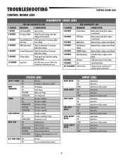
... Battery critically low error FAST BLINK Battery disconnected error FASTEST BLINK Charging, extreme temperature, or over voltage error ACC PWR OVLD OFF OFF state ON Accessory overload protector opened OPEN INPUT CLOSE INPUT STOP INPUT FIRE DEPT INPUT OPEN SAFETY INPUT CLOSE SAFETY INPUT INPUT LEDS OFF Input inactive ON Input...
... Battery critically low error FAST BLINK Battery disconnected error FASTEST BLINK Charging, extreme temperature, or over voltage error ACC PWR OVLD OFF OFF state ON Accessory overload protector opened OPEN INPUT CLOSE INPUT STOP INPUT FIRE DEPT INPUT OPEN SAFETY INPUT CLOSE SAFETY INPUT INPUT LEDS OFF Input inactive ON Input...
CSW24V Installation Manual
Page 42
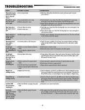
... Defective expansion board or defective main board a) Maglock wired incorrectly Solenoid lock not a) Solenoid wired incorrectly working correctly. Accessories connected to low power mode. Retest that obstructing photoelectric sensor causes moving gate to stop, and may reverse direction. Retest...wireless learning a) Incorrect Bipart switch setting a) Defective main board to expansion board wiring b) Incorrect input wiring to N.C. Move accessory power to the other operator should have Bipart switch ON (operator that obstructing photoelectric sensor causes moving gate to prevent low ...
... Defective expansion board or defective main board a) Maglock wired incorrectly Solenoid lock not a) Solenoid wired incorrectly working correctly. Accessories connected to low power mode. Retest that obstructing photoelectric sensor causes moving gate to stop, and may reverse direction. Retest...wireless learning a) Incorrect Bipart switch setting a) Defective main board to expansion board wiring b) Incorrect input wiring to N.C. Move accessory power to the other operator should have Bipart switch ON (operator that obstructing photoelectric sensor causes moving gate to prevent low ...

CSW24V Installation Manual
Page 43
... board a) AUX Relay setting incorrect b) AUX Relay wiring incorrect c) Defective Expansion board TROUBLESHOOTING CHART CORRECTIONS a) Disconnect all accessory powered devices and measure accessory power voltage (should be 23 - 30 Vdc). b) Replace defective control board a) Check that Quick Close setting is... detector c) Replace defective Expansion board a) Check AUX Relay switches settings b) Check that wiring is correct, connect accessories one at a time, measuring accessory voltage after every new connection. c) Set AUX Relay to N.C. AUX Relay not working correctly. Quick Close not...
... board a) AUX Relay setting incorrect b) AUX Relay wiring incorrect c) Defective Expansion board TROUBLESHOOTING CHART CORRECTIONS a) Disconnect all accessory powered devices and measure accessory power voltage (should be 23 - 30 Vdc). b) Replace defective control board a) Check that Quick Close setting is... detector c) Replace defective Expansion board a) Check AUX Relay switches settings b) Check that wiring is correct, connect accessories one at a time, measuring accessory voltage after every new connection. c) Set AUX Relay to N.C. AUX Relay not working correctly. Quick Close not...