CSW24V Quick Start Guide Manual
Page 1
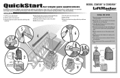
...cover using the 5/16-18 screw. Tabs on Rear Cover 5/16-18 Screw 4 Concrete Anchors 1/2" x 3 1/2" 2 6 inches (check local and national codes) 1 24 inches 28 inches 9 Slots on Chassis 5/16-18 Hex Bolts and Washers Groove on the gate (1/4 the length of the purchaser, installer and end user... to the installation manual for single gate applications MODEL CSW24V™ & CSW24VH™ This QuickStart is level. 5 Weld the gate bracket and long arm section in this position. 6 Weld...
...cover using the 5/16-18 screw. Tabs on Rear Cover 5/16-18 Screw 4 Concrete Anchors 1/2" x 3 1/2" 2 6 inches (check local and national codes) 1 24 inches 28 inches 9 Slots on Chassis 5/16-18 Hex Bolts and Washers Groove on the gate (1/4 the length of the purchaser, installer and end user... to the installation manual for single gate applications MODEL CSW24V™ & CSW24VH™ This QuickStart is level. 5 Weld the gate bracket and long arm section in this position. 6 Weld...
CSW24V Installation Manual
Page 3
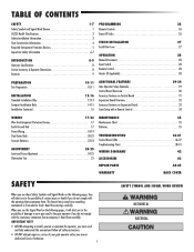
... Continued 16 PROGRAMMING 26 Remote Controls 26 Erase All Codes 26 FINISH INSTALLATION 27 Install the Cover 27 OPERATION 28 Manual Disconnect 28 Reset Switch 28 Remote Control 28 Heater (If Applicable 28 ADDITIONAL FEATURES 29-34 Gate Operator Setup Examples...24-25 Obstruction Test 25 MAINTENANCE 35 Maintenance Chart 35 Batteries 35 TROUBLESHOOTING 36-41 Control Board LEDs 36-37 Troubleshooting Chart 38-41 WIRING DIAGRAMS 42 ACCESSORIES 43 REPAIR PARTS 44-45 WARRANTY BACK COVER SAFETY SAFETY SYMBOL AND SIGNAL WORD REVIEW When you see this manual...
... Continued 16 PROGRAMMING 26 Remote Controls 26 Erase All Codes 26 FINISH INSTALLATION 27 Install the Cover 27 OPERATION 28 Manual Disconnect 28 Reset Switch 28 Remote Control 28 Heater (If Applicable 28 ADDITIONAL FEATURES 29-34 Gate Operator Setup Examples...24-25 Obstruction Test 25 MAINTENANCE 35 Maintenance Chart 35 Batteries 35 TROUBLESHOOTING 36-41 Control Board LEDs 36-37 Troubleshooting Chart 38-41 WIRING DIAGRAMS 42 ACCESSORIES 43 REPAIR PARTS 44-45 WARRANTY BACK COVER SAFETY SAFETY SYMBOL AND SIGNAL WORD REVIEW When you see this manual...
CSW24V Installation Manual
Page 11
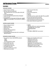
...field change) • DC motor with extended brush life • AC powered with integrated Evercharge battery backup and management • 24 Vdc accessory power • Programmable with Fail Safe/Fail Secure selection • Quick-Close ON/OFF selection switch • AC Fail... Radio Receiver and 3-Button Station control, six radio frequencies supporting Security✚ 2.0™ • COMMANDS: - TAMPER: ON when gate manually pulled from the remote control • Wireless primary/secondary (refer to pages 20 and 21) CONTROL BOARD FEATURES • Electronic Limit adjustment...
...field change) • DC motor with extended brush life • AC powered with integrated Evercharge battery backup and management • 24 Vdc accessory power • Programmable with Fail Safe/Fail Secure selection • Quick-Close ON/OFF selection switch • AC Fail... Radio Receiver and 3-Button Station control, six radio frequencies supporting Security✚ 2.0™ • COMMANDS: - TAMPER: ON when gate manually pulled from the remote control • Wireless primary/secondary (refer to pages 20 and 21) CONTROL BOARD FEATURES • Electronic Limit adjustment...
CSW24V Manual
Page 3
...21-22 Limit and Force Adjustment 21-22 Obstruction Test 22 PROGRAMMING 23 Remote Controls 23 Erase All Codes 23 FINISH INSTALLATION 24 Install the Cover 24 OPERATION 25 Reset Switch 25 Remote Control 25 Heater (If Applicable 25 ADDITIONAL FEATURES 26-32 Control Board Overview 26 Accessory ...LEDs 34-35 Troubleshooting Chart 36-39 REPAIR PARTS 40-41 ACCESSORIES 42-43 WIRING DIAGRAM 44 WARRANTY 45 SAFETY When you see this manual and follow all safety instructions. • DO NOT attempt repair or service of damage to the possibility of your gate and/or ...
...21-22 Limit and Force Adjustment 21-22 Obstruction Test 22 PROGRAMMING 23 Remote Controls 23 Erase All Codes 23 FINISH INSTALLATION 24 Install the Cover 24 OPERATION 25 Reset Switch 25 Remote Control 25 Heater (If Applicable 25 ADDITIONAL FEATURES 26-32 Control Board Overview 26 Accessory ...LEDs 34-35 Troubleshooting Chart 36-39 REPAIR PARTS 40-41 ACCESSORIES 42-43 WIRING DIAGRAM 44 WARRANTY 45 SAFETY When you see this manual and follow all safety instructions. • DO NOT attempt repair or service of damage to the possibility of your gate and/or ...
CSW24V Manual
Page 11
...OPEN, CLOSE, or STOP: accessory connection and on-board button - FIRE DEPARTMENT OPEN: accessory connection - TAMPER: ON when gate manually pulled from the remote control • Wireless primary/secondary (refer to pages 17-18) CONTROL BOARD FEATURES • Electronic Limit adjustment...field change) • DC motor with extended brush life • AC powered with integrated Evercharge battery backup and management • 24 Vdc accessory power • Programmable with AC or Solar power available - INTRODUCTION FEATURES FEATURES OPERATOR FEATURES • Advanced "Centerpiece" ...
...OPEN, CLOSE, or STOP: accessory connection and on-board button - FIRE DEPARTMENT OPEN: accessory connection - TAMPER: ON when gate manually pulled from the remote control • Wireless primary/secondary (refer to pages 17-18) CONTROL BOARD FEATURES • Electronic Limit adjustment...field change) • DC motor with extended brush life • AC powered with integrated Evercharge battery backup and management • 24 Vdc accessory power • Programmable with AC or Solar power available - INTRODUCTION FEATURES FEATURES OPERATOR FEATURES • Advanced "Centerpiece" ...


