LiftMaster Gate Operator Feature Chart Manual
Page 1
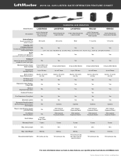
... 325 LISTED GATE OPERATOR FEATURE CHART Model Number Description Battery Backup Powers up when the power's down Security+ 2.0® 3 Channel Receiver Virtually eliminates interference and extends range MyQ® Controls your gate from anywhere with your smartphone P3 Motor® Meets the exact requirements needed to move your gate Monitored Safety Inputs (Color Coded) Exceptional Standby Power Best-in-Class Solar Performance* DC Motor with Soft Start/Stop Diagnostic Code Display2 Digit LED Wireless Dual-Gate Operation...
... 325 LISTED GATE OPERATOR FEATURE CHART Model Number Description Battery Backup Powers up when the power's down Security+ 2.0® 3 Channel Receiver Virtually eliminates interference and extends range MyQ® Controls your gate from anywhere with your smartphone P3 Motor® Meets the exact requirements needed to move your gate Monitored Safety Inputs (Color Coded) Exceptional Standby Power Best-in-Class Solar Performance* DC Motor with Soft Start/Stop Diagnostic Code Display2 Digit LED Wireless Dual-Gate Operation...
LiftMaster Gate Operator Feature Chart Manual
Page 2
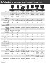
... Loop Detector Inputs (LOOPDETLM) Pre-Motion Warning Alarm Dual Voltage Warranty Period Yes Yes 120/230V Single Phase 7 years Res. 5 years Comm. Diagnostic Code Display2 Digit LED Yes Yes Yes Yes Yes Yes Yes Wireless Dual-Gate Operation Yes Yes Yes Yes Yes Yes Yes PosiLock® Feature - 2016 UL 325 LISTED GATE OPERATOR FEATURE CHART Model Number ELITE® SERIES DC COMMERCIAL GATE OPERATORS CSW24U CSL24U HCTDCU ELITE® SERIES AC COMMERCIAL...
... Loop Detector Inputs (LOOPDETLM) Pre-Motion Warning Alarm Dual Voltage Warranty Period Yes Yes 120/230V Single Phase 7 years Res. 5 years Comm. Diagnostic Code Display2 Digit LED Yes Yes Yes Yes Yes Yes Yes Wireless Dual-Gate Operation Yes Yes Yes Yes Yes Yes Yes PosiLock® Feature - 2016 UL 325 LISTED GATE OPERATOR FEATURE CHART Model Number ELITE® SERIES DC COMMERCIAL GATE OPERATORS CSW24U CSL24U HCTDCU ELITE® SERIES AC COMMERCIAL...
CSW200501U Setup and Operation Manual
Page 2
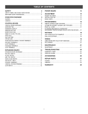
... POWER BOARD 13 ADJUSTMENT 14 ADJUST THE LIMITS 14 OBSTRUCTION TEST 15 ERASE LIMITS 15 PROGRAMMING 16 REMOTE CONTROLS (NOT PROVIDED 16 LIFTMASTER INTERNET GATEWAY (NOT PROVIDED 17 ERASE ALL CODES 17 TO REMOVE AND ERASE ALL MONITORED ENTRAPMENT PROTECTION AND VEHICLE DETECTION DEVICES.....17 SETTINGS 18 GATE OPERATOR SETUP EXAMPLES 18 DUAL GATE SETTINGS 19 WIRING 19 SAMS WIRING WITH RELAYS NOT ENERGIZED 19 FIELD WIRING 20 MAINTENANCE 21 MAINTENANCE 21 TROUBLESHOOTING 22 DIAGNOSTIC CODES 22 OPERATOR...
... POWER BOARD 13 ADJUSTMENT 14 ADJUST THE LIMITS 14 OBSTRUCTION TEST 15 ERASE LIMITS 15 PROGRAMMING 16 REMOTE CONTROLS (NOT PROVIDED 16 LIFTMASTER INTERNET GATEWAY (NOT PROVIDED 17 ERASE ALL CODES 17 TO REMOVE AND ERASE ALL MONITORED ENTRAPMENT PROTECTION AND VEHICLE DETECTION DEVICES.....17 SETTINGS 18 GATE OPERATOR SETUP EXAMPLES 18 DUAL GATE SETTINGS 19 WIRING 19 SAMS WIRING WITH RELAYS NOT ENERGIZED 19 FIELD WIRING 20 MAINTENANCE 21 MAINTENANCE 21 TROUBLESHOOTING 22 DIAGNOSTIC CODES 22 OPERATOR...

CSW200501U Setup and Operation Manual
Page 3
... INSTRUCTIONS. • ANY maintenance to your gate operator unless you are no obstructions to adjust and retest the gate operator properly can be performed until disconnecting the electrical power (AC or solar and battery) and locking-out the power via the operator power switch. SAFETY SAFETY SYMBOL AND SIGNAL WORD REVIEW When you see this manual and follow all safety instructions. • DO NOT attempt repair or service of your gate and/or the gate operator...
... INSTRUCTIONS. • ANY maintenance to your gate operator unless you are no obstructions to adjust and retest the gate operator properly can be performed until disconnecting the electrical power (AC or solar and battery) and locking-out the power via the operator power switch. SAFETY SAFETY SYMBOL AND SIGNAL WORD REVIEW When you see this manual and follow all safety instructions. • DO NOT attempt repair or service of your gate and/or the gate operator...

CSW200501U Setup and Operation Manual
Page 4
... the reset button to stop a moving gate during a normal open/close the gate. SL3000U OPERATOR OVERVIEW DUST GUARD ANTENNA POWER BOARD (Located behind the control board) Page 13 LIMIT SWITCHES Pages 14-15 CONTROL BOARD Pages 5-9 EXPANSION BOARD Pages 10-13 ACCESSORY POWER OUTLET AC POWER SWITCH The AC Power switch on the operator will stay in open and close cycle, like a stop button. • Press the reset button once while the gate is in the open position. JUNCTION BOX Page 20 JUNCTION BOX Page 20 COVER MANUAL RELEASE...
... the reset button to stop a moving gate during a normal open/close the gate. SL3000U OPERATOR OVERVIEW DUST GUARD ANTENNA POWER BOARD (Located behind the control board) Page 13 LIMIT SWITCHES Pages 14-15 CONTROL BOARD Pages 5-9 EXPANSION BOARD Pages 10-13 ACCESSORY POWER OUTLET AC POWER SWITCH The AC Power switch on the operator will stay in open and close cycle, like a stop button. • Press the reset button once while the gate is in the open position. JUNCTION BOX Page 20 JUNCTION BOX Page 20 COVER MANUAL RELEASE...

CSW200501U Setup and Operation Manual
Page 5
...-Close either press the reset button or activate the gate with a programmed remote control. • Press the reset button to -Close. The gate will turn the incoming 120/240 Vac power ON or OFF. OPERATOR ARM REAR COVER JUNCTION BOX Page 20 ACCESSORY POWER OUTLET ANTENNA CONTROL BOARD Pages 5-9 LIMIT SWITCHES Pages 14-15 AC POWER SWITCH The AC Power switch on the operator will stay in open position to disable the Timer-to shut off the alarm and reset the operator. 4 POWER BOARD (Located behind the control board...
...-Close either press the reset button or activate the gate with a programmed remote control. • Press the reset button to -Close. The gate will turn the incoming 120/240 Vac power ON or OFF. OPERATOR ARM REAR COVER JUNCTION BOX Page 20 ACCESSORY POWER OUTLET ANTENNA CONTROL BOARD Pages 5-9 LIMIT SWITCHES Pages 14-15 AC POWER SWITCH The AC Power switch on the operator will stay in open position to disable the Timer-to shut off the alarm and reset the operator. 4 POWER BOARD (Located behind the control board...

CSW200501U Setup and Operation Manual
Page 6
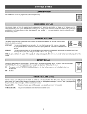
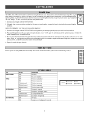
... installed. LOCK TERMINALS Page 9 ACCESSORY POWER TERMINALS CURRENT SENSOR Factory installed (model CSW200U only). CONTROL BOARD CONTROL BOARD REFERENCE BIPART DELAY Page 6 LEARN BUTTON Pages 6, 16-17 DIAGNOSTIC CODES Pages 6, 24-26 TIMER-TO-CLOSE Page 6 FORCE DIAL Page 7 BIPART DELAY 4 OPEN LEFT 2 6 OPEN 8 RIGHT HANDING HANDING BUTTONS Pages 6, 14 TEST BUTTONS Pages 7, 24 CONTROL STATION TERMINALS Page 8 FIRE DEPARTMENT TERMINALS Page 8 LOOP TERMINALS Page 8 EYES/EDGE TERMINALS Page 9 STATUS LEDS Page 7 GND ANTENNA CURRENT MOTOR DRIVE SENSOR ID RESET RPM & LIMITS...
... installed. LOCK TERMINALS Page 9 ACCESSORY POWER TERMINALS CURRENT SENSOR Factory installed (model CSW200U only). CONTROL BOARD CONTROL BOARD REFERENCE BIPART DELAY Page 6 LEARN BUTTON Pages 6, 16-17 DIAGNOSTIC CODES Pages 6, 24-26 TIMER-TO-CLOSE Page 6 FORCE DIAL Page 7 BIPART DELAY 4 OPEN LEFT 2 6 OPEN 8 RIGHT HANDING HANDING BUTTONS Pages 6, 14 TEST BUTTONS Pages 7, 24 CONTROL STATION TERMINALS Page 8 FIRE DEPARTMENT TERMINALS Page 8 LOOP TERMINALS Page 8 EYES/EDGE TERMINALS Page 9 STATUS LEDS Page 7 GND ANTENNA CURRENT MOTOR DRIVE SENSOR ID RESET RPM & LIMITS...
CSW200501U Setup and Operation Manual
Page 7
..., solenoid lock, or decorative overlay would require one gate travels a longer distance than the other . CONTROL BOARD LEARN BUTTON The LEARN button is used for programming (refer to the left when opening. NOTE: For gates installed on the left (turn counter clockwise) when opening . BIPART DELAY Used in applications where one gate to the Troubleshooting section. The TTC is reset by a "30" which direction the gate will open limit. DIAGNOSTIC DISPLAY The diagnostic display will...
..., solenoid lock, or decorative overlay would require one gate travels a longer distance than the other . CONTROL BOARD LEARN BUTTON The LEARN button is used for programming (refer to the left when opening. NOTE: For gates installed on the left (turn counter clockwise) when opening . BIPART DELAY Used in applications where one gate to the Troubleshooting section. The TTC is reset by a "30" which direction the gate will open limit. DIAGNOSTIC DISPLAY The diagnostic display will...
CSW200501U Setup and Operation Manual
Page 8
... force setting adjustment: 1. Also used for fine tuning the force in the close limits, but low enough to prevent serious injury to the Troubleshooting section). The force setting should stop and reverse upon contact with the TEST BUTTONS. 2. CONTROL BOARD FORCE DIAL The FORCE DIAL on the length and weight of the gate it may affect the gate travel. Based on the control board is the same for the open direction. If the gate stops...
... force setting adjustment: 1. Also used for fine tuning the force in the close limits, but low enough to prevent serious injury to the Troubleshooting section). The force setting should stop and reverse upon contact with the TEST BUTTONS. 2. CONTROL BOARD FORCE DIAL The FORCE DIAL on the length and weight of the gate it may affect the gate travel. Based on the control board is the same for the open direction. If the gate stops...
CSW200501U Setup and Operation Manual
Page 12
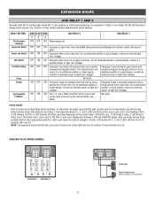
... cycles that the gate operator has run (in motion). For an sound. Not used . buzzer or light (low voltage). See below. Not used . Cycle count displayed is manually tampered with by switch settings. After servicing, set all the LEDs will turn on solid for Aux Relay 1. AUX Relay 1 N.C. RELAY SETTING Off (no feature selected) Open Limit Switch Close Limit Switch Gate Motion Pre-Motion Delay Power Tamper Cycle Quantity Feedback* SWITCH SETTINGS 123 OFF OFF OFF Relay always off of...
... cycles that the gate operator has run (in motion). For an sound. Not used . buzzer or light (low voltage). See below. Not used . Cycle count displayed is manually tampered with by switch settings. After servicing, set all the LEDs will turn on solid for Aux Relay 1. AUX Relay 1 N.C. RELAY SETTING Off (no feature selected) Open Limit Switch Close Limit Switch Gate Motion Pre-Motion Delay Power Tamper Cycle Quantity Feedback* SWITCH SETTINGS 123 OFF OFF OFF Relay always off of...
CSW200501U Setup and Operation Manual
Page 15
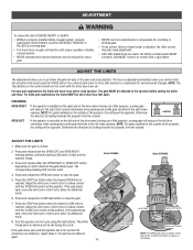
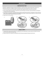
... operator has error number 50 (maximum run distance), repeat steps 1-4 to flash and the operator beeps. 3. The force is installed on the outside . ADJUST THE LIMITS 1. Press and release both the OPEN LEFT and OPEN RIGHT handing buttons until the limits have to be attached to the operator before setting the limits and force. NOTE: The Test Buttons on the control board (refer to Force Dial section) to compensate for additional travel. 6. NOTE: For gates installed...
... operator has error number 50 (maximum run distance), repeat steps 1-4 to flash and the operator beeps. 3. The force is installed on the outside . ADJUST THE LIMITS 1. Press and release both the OPEN LEFT and OPEN RIGHT handing buttons until the limits have to be attached to the operator before setting the limits and force. NOTE: The Test Buttons on the control board (refer to Force Dial section) to compensate for additional travel. 6. NOTE: For gates installed...
CSW200501U Setup and Operation Manual
Page 16
... motion, the operator will need to reach both the OPEN LEFT and OPEN RIGHT LEDs blink rapidly and the operator beeps. 2. Open and close the gate with a solid object. 4. If the gate does not reverse off the solid object, reduce the force setting by turning the force control slightly counter-clockwise. ADJUSTMENT OBSTRUCTION TEST The operator is stopping at the proper open and close direction. SENSOR ID RESET BOARD 24 VAC IN CLOSE limit OPEN limit ERASE LIMITS 1. The gate should stop the gate...
... motion, the operator will need to reach both the OPEN LEFT and OPEN RIGHT LEDs blink rapidly and the operator beeps. 2. Open and close the gate with a solid object. 4. If the gate does not reverse off the solid object, reduce the force setting by turning the force control slightly counter-clockwise. ADJUSTMENT OBSTRUCTION TEST The operator is stopping at the proper open and close direction. SENSOR ID RESET BOARD 24 VAC IN CLOSE limit OPEN limit ERASE LIMITS 1. The gate should stop the gate...

CSW200501U Setup and Operation Manual
Page 17
... 50 Security+ 2.0™ remote controls and 2 keyless entries (1 PIN for each remote control button 1. The Timer-to be programmed. During the open the gate. Connect the equipment into an outlet on , the user is subject to the following measures: - LED will close the gate. The operator will automatically exit learn mode (operator will beep and green XMITTER LED will open cycle another activation of the remote control will stop . 1. Once the remote control has been programmed the operator will operate as an open the gate. Any changes...
... 50 Security+ 2.0™ remote controls and 2 keyless entries (1 PIN for each remote control button 1. The Timer-to be programmed. During the open the gate. Connect the equipment into an outlet on , the user is subject to the following measures: - LED will close the gate. The operator will automatically exit learn mode (operator will beep and green XMITTER LED will open cycle another activation of the remote control will stop . 1. Once the remote control has been programmed the operator will operate as an open the gate. Any changes...

CSW200501U Setup and Operation Manual
Page 18
... reset button 3 times (on primary gate) to the LiftMaster Internet Gateway: Program using the reset button on the operator's control board: 1. Press and hold the LEARN button again until the green XMITTER LED flashes and then release the button (approximately 6 seconds). Remove the entrapment protection or vehicle detection device wires from the terminal block. 2. Press the OPEN LEFT and OPEN RIGHT buttons simultaneously to the operator if it is within range and the operator will beep if programming is closed ". Connect power...
... reset button 3 times (on primary gate) to the LiftMaster Internet Gateway: Program using the reset button on the operator's control board: 1. Press and hold the LEARN button again until the green XMITTER LED flashes and then release the button (approximately 6 seconds). Remove the entrapment protection or vehicle detection device wires from the terminal block. 2. Press the OPEN LEFT and OPEN RIGHT buttons simultaneously to the operator if it is within range and the operator will beep if programming is closed ". Connect power...
CSW200501U Setup and Operation Manual
Page 19
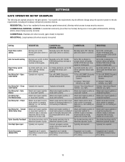
... batteries). Your specific site requirements may be different. COMMERCIAL/ GENERAL ACCESS Normally set to ON for gate that delays upon opening . 1) Use with by being pushed off of close limit. Connect emergency access system (Knox box switch, SOS system, etc.). Normal gate close (timer or control). Typically not required. Normally set to OFF. Normal gate close (timer or control). light). Typically not required. For DUAL-GATE site, set to ON for gate that gate closes immediately after vehicle passes CLOSE EYES/ Interrupt loop. Always setup...
... batteries). Your specific site requirements may be different. COMMERCIAL/ GENERAL ACCESS Normally set to ON for gate that delays upon opening . 1) Use with by being pushed off of close limit. Connect emergency access system (Knox box switch, SOS system, etc.). Normal gate close (timer or control). Typically not required. Normally set to OFF. Normal gate close (timer or control). light). Typically not required. For DUAL-GATE site, set to ON for gate that gate closes immediately after vehicle passes CLOSE EYES/ Interrupt loop. Always setup...

CSW200501U Setup and Operation Manual
Page 20
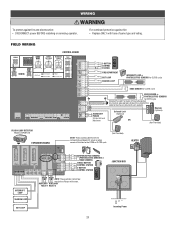
... CLOSE Switch ANTI-TAIL Switch PRIMARY OPERATOR ON ON SECONDARY OPERATOR OFF OFF WIRING SAMS WIRING WITH RELAYS NOT ENERGIZED Control Board BIPART DELAY 4 2 6 OPEN LEFT OPEN 8 RIGHT HANDING Exit Input Barrier Arm Operator C Auxiliary Command NO COMM LINK BA CLASS 2 SUPPLY 24 VAC 500 mA MAX GND ANTENNA CURRENT MOTOR DRIVE SENSOR ID RESET RPM & LIMITS ALARM EXP. BOARD 24 VAC IN Expansion Board POWER TO MAIN BOARD SHADOW INTERUPT EXIT OPEN CLOSE DEVICE INPUTS 1 EYE ONLY 2 EYE/ EDGE 3 EYE...
... CLOSE Switch ANTI-TAIL Switch PRIMARY OPERATOR ON ON SECONDARY OPERATOR OFF OFF WIRING SAMS WIRING WITH RELAYS NOT ENERGIZED Control Board BIPART DELAY 4 2 6 OPEN LEFT OPEN 8 RIGHT HANDING Exit Input Barrier Arm Operator C Auxiliary Command NO COMM LINK BA CLASS 2 SUPPLY 24 VAC 500 mA MAX GND ANTENNA CURRENT MOTOR DRIVE SENSOR ID RESET RPM & LIMITS ALARM EXP. BOARD 24 VAC IN Expansion Board POWER TO MAIN BOARD SHADOW INTERUPT EXIT OPEN CLOSE DEVICE INPUTS 1 EYE ONLY 2 EYE/ EDGE 3 EYE...
CSW200501U Setup and Operation Manual
Page 21
... or EDGE SENSORS SINGLE BUTTON CONTROL STATION 3-BUTTON CONTROL STATION JUNCTION BOX N.C. NOTE: These switches control how the Auxiliary Relays will function for CLOSE cycle - + SHADOW LOOP - + - + - + N.C. AUXILIARY AUXILIARY RELAY 1 RELAY 2 GND N L EXIT LOOP Incoming Power 20 N.C. COM N.O. - N.C. N.C. WIRING To protect against fire: • Replace ONLY with fuse of each operator. FIELD WIRING BIPART DELAY 4 2 6 OPEN LEFT OPEN 8 RIGHT HANDING CONTROL BOARD GND ANTENNA CURRENT MOTOR DRIVE SENSOR ID RESET RPM & LIMITS ALARM EXP. BOARD 24 VAC IN CLASS...
... or EDGE SENSORS SINGLE BUTTON CONTROL STATION 3-BUTTON CONTROL STATION JUNCTION BOX N.C. NOTE: These switches control how the Auxiliary Relays will function for CLOSE cycle - + SHADOW LOOP - + - + - + N.C. AUXILIARY AUXILIARY RELAY 1 RELAY 2 GND N L EXIT LOOP Incoming Power 20 N.C. COM N.O. - N.C. N.C. WIRING To protect against fire: • Replace ONLY with fuse of each operator. FIELD WIRING BIPART DELAY 4 2 6 OPEN LEFT OPEN 8 RIGHT HANDING CONTROL BOARD GND ANTENNA CURRENT MOTOR DRIVE SENSOR ID RESET RPM & LIMITS ALARM EXP. BOARD 24 VAC IN CLASS...
CSW200501U Setup and Operation Manual
Page 24
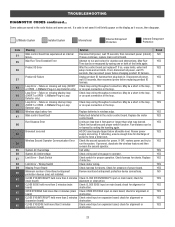
... expansion board; Loop Error - Failure or missing interrupt loop (SHORT or OPEN - Wireless edge battery low Replace batteries in the loop. Review power supply and wiring. System AC Undervoltage Check wiring and wire gauge to force a fresh boot. Stuck Switch Check switch for (main board) alignment or obstruction. Minimum number of monitored entrapment protection devices (one or both of the limits again. CLOSE EYE/INTERRUPT held more than what was learned. LiftMaster System Installed System Informational External...
... expansion board; Loop Error - Failure or missing interrupt loop (SHORT or OPEN - Wireless edge battery low Replace batteries in the loop. Review power supply and wiring. System AC Undervoltage Check wiring and wire gauge to force a fresh boot. Stuck Switch Check switch for (main board) alignment or obstruction. Minimum number of monitored entrapment protection devices (one or both of the limits again. CLOSE EYE/INTERRUPT held more than what was learned. LiftMaster System Installed System Informational External...

CSW200501U Setup and Operation Manual
Page 25
... from other operator Open input (EYE/EDGE) communication fault from other operator Close input (EYE/EDGE) communication fault (expansion board) Open input (EYE/EDGE) communication fault (expansion board) Force Reversal RPM / STALL Reversal AC motor no action required. Check inputs and communication method between operators, either wired bus or radio. Check wired input for an obstructed gate or binding a mechanism. Check inputs and communication method between operators, either wired bus or radio. TROUBLESHOOTING DIAGNOSTIC CODES continued...
... from other operator Open input (EYE/EDGE) communication fault from other operator Close input (EYE/EDGE) communication fault (expansion board) Open input (EYE/EDGE) communication fault (expansion board) Force Reversal RPM / STALL Reversal AC motor no action required. Check inputs and communication method between operators, either wired bus or radio. Check wired input for an obstructed gate or binding a mechanism. Check inputs and communication method between operators, either wired bus or radio. TROUBLESHOOTING DIAGNOSTIC CODES continued...
CSW200501U Setup and Operation Manual
Page 30
... ARISING IN CONNECTION WITH USE, OR INABILITY TO USE, THIS PRODUCT. THIS LIMITED WARRANTY DOES NOT COVER ANY PROBLEMS WITH, OR RELATING TO, THE GATE OR GATE HARDWARE, INCLUDING BUT NOT LIMITED TO THE GATE SPRINGS, GATE ROLLERS, GATE ALIGNMENT OR HINGES. The proper operation of -purchase receipt with new or factory-rebuilt parts at no cost to you call 1-800-528-2806, toll free, before dismantling...
... ARISING IN CONNECTION WITH USE, OR INABILITY TO USE, THIS PRODUCT. THIS LIMITED WARRANTY DOES NOT COVER ANY PROBLEMS WITH, OR RELATING TO, THE GATE OR GATE HARDWARE, INCLUDING BUT NOT LIMITED TO THE GATE SPRINGS, GATE ROLLERS, GATE ALIGNMENT OR HINGES. The proper operation of -purchase receipt with new or factory-rebuilt parts at no cost to you call 1-800-528-2806, toll free, before dismantling...


