CSL24U Sell Sheet Manual
Page 2
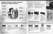
CSL24U: Setting the New Standard with Best-in-Class Features ... at each entrapment point, including: - Keyed Manual Disconnect when unlocked allows gate to maximize cycles when operating on Battery Backup. WARRANTY Five years commercial. LiftMaster has designed its path. LiftMaster Monitored Photo Eyes and/or Edge Sensors** •...helping the industry design, install and service safe gate applications that virtually eliminates interference and offers extended range each LiftMaster Gate Operator - A general range estimate is 300 ft. † MultiCode is dependent on battery backup....
CSL24U: Setting the New Standard with Best-in-Class Features ... at each entrapment point, including: - Keyed Manual Disconnect when unlocked allows gate to maximize cycles when operating on Battery Backup. WARRANTY Five years commercial. LiftMaster has designed its path. LiftMaster Monitored Photo Eyes and/or Edge Sensors** •...helping the industry design, install and service safe gate applications that virtually eliminates interference and offers extended range each LiftMaster Gate Operator - A general range estimate is 300 ft. † MultiCode is dependent on battery backup....

CSL24U Wiring Diagram Manual
Page 1
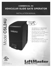
...battery. May have a 12V battery on Limit and Force Adjustment, and Obstruction Test in the manual. 93 RPM / STALL Reversal (Operator 1) RPM / STALL Reversal (Operator 2) 94 Check...... ...then press and hold OPEN until "Er" shows. CODE COLOR KEY: LiftMaster System Installed System Informational External Entrapment Protection Inherent Entrapment Protection CODE MEANING SOLUTION Main...N.C. See section on a 24V system. Control Station Fire Department WIRING DIAGRAM Model CSL24U Exit Loop Shadow Loop LOOPS DIAGNOSTICS Interrupt Loop Photoelectric Sensors for close cycle ENTRAPMENT ...
...battery. May have a 12V battery on Limit and Force Adjustment, and Obstruction Test in the manual. 93 RPM / STALL Reversal (Operator 1) RPM / STALL Reversal (Operator 2) 94 Check...... ...then press and hold OPEN until "Er" shows. CODE COLOR KEY: LiftMaster System Installed System Informational External Entrapment Protection Inherent Entrapment Protection CODE MEANING SOLUTION Main...N.C. See section on a 24V system. Control Station Fire Department WIRING DIAGRAM Model CSL24U Exit Loop Shadow Loop LOOPS DIAGNOSTICS Interrupt Loop Photoelectric Sensors for close cycle ENTRAPMENT ...
CSL24U Installation Manual
Page 1
LiftMaster 845 Larch Avenue Elmhurst, IL 60126-1196 Model CSL24U COMMERCIAL DC VEHICULAR SLIDE GATE OPERATOR INSTALLATION MANUAL • THIS PRODUCT IS TO BE INSTALLED AND SERVICED BY A TRAINED GATE SYSTEMS TECHNICIAN ONLY. • This model is for use on vehicular passage gates... use on pedestrian passage gates. • This model is intended for use in Class I, II, III and IV vehicular slide gate applications. • Visit LiftMaster.com to locate a professional installing dealer in your area. • This gate operator is compatible with MyQ® and Security+ 2.0® accessories.
LiftMaster 845 Larch Avenue Elmhurst, IL 60126-1196 Model CSL24U COMMERCIAL DC VEHICULAR SLIDE GATE OPERATOR INSTALLATION MANUAL • THIS PRODUCT IS TO BE INSTALLED AND SERVICED BY A TRAINED GATE SYSTEMS TECHNICIAN ONLY. • This model is for use on vehicular passage gates... use on pedestrian passage gates. • This model is intended for use in Class I, II, III and IV vehicular slide gate applications. • Visit LiftMaster.com to locate a professional installing dealer in your area. • This gate operator is compatible with MyQ® and Security+ 2.0® accessories.
CSL24U Installation Manual
Page 3
... GATES ONLY 20 INSTALL THE COVER 22 ADJUSTMENT 23 LIMIT AND FORCE ADJUSTMENT 23 PROGRAMMING 25 REMOTE CONTROLS (NOT PROVIDED 25 LIFTMASTER INTERNET GATEWAY (NOT PROVIDED 26 ERASE ALL CODES 26 ERASE LIMITS 26 TO REMOVE AND ERASE MONITORED ENTRAPMENT PROTECTION DEVICES 26... OPERATION 27 GATE OPERATOR SETUP EXAMPLES 27 CONTROL BOARD OVERVIEW 28 RESET SWITCH 29 MANUAL DISCONNECT 29 OPERATOR ALARM 29 REMOTE CONTROL 29 ACCESSORY WIRING 30 EXTERNAL CONTROL DEVICES 30 LOCKS 31 MISCELLANEOUS WIRING 31 EXPANSION...
... GATES ONLY 20 INSTALL THE COVER 22 ADJUSTMENT 23 LIMIT AND FORCE ADJUSTMENT 23 PROGRAMMING 25 REMOTE CONTROLS (NOT PROVIDED 25 LIFTMASTER INTERNET GATEWAY (NOT PROVIDED 26 ERASE ALL CODES 26 ERASE LIMITS 26 TO REMOVE AND ERASE MONITORED ENTRAPMENT PROTECTION DEVICES 26... OPERATION 27 GATE OPERATOR SETUP EXAMPLES 27 CONTROL BOARD OVERVIEW 28 RESET SWITCH 29 MANUAL DISCONNECT 29 OPERATOR ALARM 29 REMOTE CONTROL 29 ACCESSORY WIRING 30 EXTERNAL CONTROL DEVICES 30 LOCKS 31 MISCELLANEOUS WIRING 31 EXPANSION...
CSL24U Installation Manual
Page 4
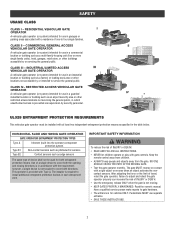
... or DEATH. • Use the emergency release ONLY when the gate is prevented via supervision by or intended to four single families. Read the owner's manual. Have a qualified service person make repairs to cover both the opening and closing directions is for use separate entrance. • SAVE THESE INSTRUCTIONS. 2 RESIDENTIAL VEHICULAR...
... or DEATH. • Use the emergency release ONLY when the gate is prevented via supervision by or intended to four single families. Read the owner's manual. Have a qualified service person make repairs to cover both the opening and closing directions is for use separate entrance. • SAVE THESE INSTRUCTIONS. 2 RESIDENTIAL VEHICULAR...

CSL24U Installation Manual
Page 5
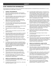
... gate must reduce public exposure to reduce the risk of non-contact sensor for entrapment protection functions shall be incorporated into every design. Reference owner's manual regarding placement of nuisance tripping, such as one component. b. Care shall be properly installed and work freely in that portion of the adjacent fence that...
... gate must reduce public exposure to reduce the risk of non-contact sensor for entrapment protection functions shall be incorporated into every design. Reference owner's manual regarding placement of nuisance tripping, such as one component. b. Care shall be properly installed and work freely in that portion of the adjacent fence that...
CSL24U Installation Manual
Page 6
... and installed to perform their intended function. 4. For pedestrian access in the vicinity of an automated vehicular gate, a separate pedestrian gate shall be disabled when a manually operated gate is less, to the application in the open position or the fully closed positions. An existing gate latch shall be provided. For a copy...
... and installed to perform their intended function. 4. For pedestrian access in the vicinity of an automated vehicular gate, a separate pedestrian gate shall be disabled when a manually operated gate is less, to the application in the open position or the fully closed positions. An existing gate latch shall be provided. For a copy...

CSL24U Installation Manual
Page 14
...10 feet of chain length. Connect the chain to the ground. INSTALLATION STEP 3 ATTACH THE CHAIN STANDARD INSTALLATION DO NOT run the operator until instructed. 1. Manually open the gate and line up the rear bracket so the chain will be level with the idler pulley and parallel to the brackets using... the eye bolt hardware. Weld the front bracket in this position. 2. Manually close the gate and line up the front bracket so the chain will be level with the idler pulley and parallel to the ground. Remove...
...10 feet of chain length. Connect the chain to the ground. INSTALLATION STEP 3 ATTACH THE CHAIN STANDARD INSTALLATION DO NOT run the operator until instructed. 1. Manually open the gate and line up the rear bracket so the chain will be level with the idler pulley and parallel to the brackets using... the eye bolt hardware. Weld the front bracket in this position. 2. Manually close the gate and line up the front bracket so the chain will be level with the idler pulley and parallel to the ground. Remove...

CSL24U Installation Manual
Page 15
... DO NOT run the operator until instructed. Refer to Gate Construction Information on the gear box. Remove the pin from the vent plug on page 4. 1. Manually close the gate and align the bottom bracket so the chain will be level with the bottom idler pulley and parallel to the ground. INSTALLATION...
... DO NOT run the operator until instructed. Refer to Gate Construction Information on the gear box. Remove the pin from the vent plug on page 4. 1. Manually close the gate and align the bottom bracket so the chain will be level with the bottom idler pulley and parallel to the ground. INSTALLATION...

CSL24U Installation Manual
Page 17
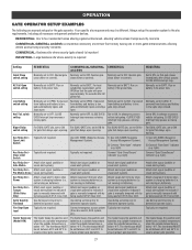
... settings (located next to the terminals) Switch set to CLOSE: gate reverses fully when obstruction is sensed Switch set to the specific entrapment protection device manual for monitored devices, which include pulsed photoelectric sensors, resistive edge sensors, and pulsed edge sensors.
... settings (located next to the terminals) Switch set to CLOSE: gate reverses fully when obstruction is sensed Switch set to the specific entrapment protection device manual for monitored devices, which include pulsed photoelectric sensors, resistive edge sensors, and pulsed edge sensors.
CSL24U Installation Manual
Page 29
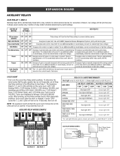
...to CLOSE. Aux Relay Out - Typically not required. not running on batteries). Use during servicing only to know when system is manually tampered with by being pushed off of close (timer or control). The heater keeps the gearbox and batteries at a suitable temperature...indicator (e.g. Attach visual alert to ensure proper gate operation. The thermostat MUST be different. Normally set to know when system is manually tampered with by being pushed off of close limit. Attach alert signal (audible or visual alert system). If powered from battery ...
...to CLOSE. Aux Relay Out - Typically not required. not running on batteries). Use during servicing only to know when system is manually tampered with by being pushed off of close (timer or control). The heater keeps the gearbox and batteries at a suitable temperature...indicator (e.g. Attach visual alert to ensure proper gate operation. The thermostat MUST be different. Normally set to know when system is manually tampered with by being pushed off of close limit. Attach alert signal (audible or visual alert system). If powered from battery ...

CSL24U Installation Manual
Page 30
... select switch set to OPEN forces gate to automatically open and then latch at the OPEN limit until AC power is factory set to MANUAL will either open or close photoelectric sensors (IR's). 8 REVERSAL FORCE dial: The REVERSAL FORCE dial adjusts the force. The TTC is .... See Bipart Delay section. 6 LEARN Button: The LEARN button is in the Troubleshooting section. 11 DIAGNOSTICS Display: The diagnostics display will display as CSL24U. The range is 0 to open controls, loops, close edges, and close the gate when the operator is for dual gates. See Force Adjustment section...
... select switch set to OPEN forces gate to automatically open and then latch at the OPEN limit until AC power is factory set to MANUAL will either open or close photoelectric sensors (IR's). 8 REVERSAL FORCE dial: The REVERSAL FORCE dial adjusts the force. The TTC is .... See Bipart Delay section. 6 LEARN Button: The LEARN button is in the Troubleshooting section. 11 DIAGNOSTICS Display: The diagnostics display will display as CSL24U. The range is 0 to open controls, loops, close edges, and close the gate when the operator is for dual gates. See Force Adjustment section...

CSL24U Installation Manual
Page 31
The reset switch will disable the gate in the closed manually. If a command is closing, the gate will stop and the next activation will open the gate. The gate does not meet specifications. The gate has ... functions will beep 3 times with a command if the battery is hitting a wall or vehicle. After the operator is off the alarm and reset the operator. MANUAL DISCONNECT Press the reset switch to RESET/DISCONNECT to allow the gate to be reset: A. The gate is low. Remove any obstructions. Toggling the reset...
The reset switch will disable the gate in the closed manually. If a command is closing, the gate will stop and the next activation will open the gate. The gate does not meet specifications. The gate has ... functions will beep 3 times with a command if the battery is hitting a wall or vehicle. After the operator is off the alarm and reset the operator. MANUAL DISCONNECT Press the reset switch to RESET/DISCONNECT to allow the gate to be reset: A. The gate is low. Remove any obstructions. Toggling the reset...
CSL24U Installation Manual
Page 35
... connect an external light (low voltage). For an additional audible energized during Energizes 3 seconds before relay cutoff, after AC shutdown. There is manually tampered with barrier gate). See below. To determine the actual cycles that the gate operator has run (in motion). If under 1,000 cycles...1000's, 2 LED blinking 10,000's, 3 LED blinking 100,000's, and simultaneously all the LEDs will blink out the cycle count (cycle count is manually tampered with by switch settings. AUX Relay 1 N.C. Function of Class 2, low voltage (42 Vdc [34 Vac] max 5 Amps) power sources only...
... connect an external light (low voltage). For an additional audible energized during Energizes 3 seconds before relay cutoff, after AC shutdown. There is manually tampered with barrier gate). See below. To determine the actual cycles that the gate operator has run (in motion). If under 1,000 cycles...1000's, 2 LED blinking 10,000's, 3 LED blinking 100,000's, and simultaneously all the LEDs will blink out the cycle count (cycle count is manually tampered with by switch settings. AUX Relay 1 N.C. Function of Class 2, low voltage (42 Vdc [34 Vac] max 5 Amps) power sources only...
CSL24U Installation Manual
Page 37
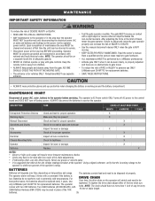
... and need to gate hardware. • ALL maintenance MUST be performed by a LiftMaster professional. • Activate gate ONLY when it can increase the risk of INJURY or DEATH. • Use the manual disconnect release ONLY when the gate is within ten percent of adequate capacity. •...adjust and retest the gate operator properly can be reset after any major drive chain adjustments. • If lubricating chain, use ONLY LiftMaster part 29-NP712 for vehicles ONLY. For best performance, the batteries should be used in extremely cold temperatures. Two 33AH batteries (A12330SGLPK...
... and need to gate hardware. • ALL maintenance MUST be performed by a LiftMaster professional. • Activate gate ONLY when it can increase the risk of INJURY or DEATH. • Use the manual disconnect release ONLY when the gate is within ten percent of adequate capacity. •...adjust and retest the gate operator properly can be reset after any major drive chain adjustments. • If lubricating chain, use ONLY LiftMaster part 29-NP712 for vehicles ONLY. For best performance, the batteries should be used in extremely cold temperatures. Two 33AH batteries (A12330SGLPK...
CSL24U Installation Manual
Page 42
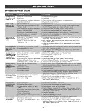
... g) Defective control board g) Replace defective control board Gate moves, but will not open or fully close (slide gate applications only) a) Use manual disconnect, manually move easily and freely through its entire range, limit to limit. Gate closes, but motor does not run and error code b) Open fuse ...an active detector c) Check AC power and AC Fail option setting d) Check if AC power is too difficult to move a) Use manual disconnect, manually move c) Limits are set correct limits. Charge batteries by AC or solar power or replace batteries. Charge batteries by AC or ...
... g) Defective control board g) Replace defective control board Gate moves, but will not open or fully close (slide gate applications only) a) Use manual disconnect, manually move easily and freely through its entire range, limit to limit. Gate closes, but motor does not run and error code b) Open fuse ...an active detector c) Check AC power and AC Fail option setting d) Check if AC power is too difficult to move a) Use manual disconnect, manually move c) Limits are set correct limits. Charge batteries by AC or solar power or replace batteries. Charge batteries by AC or ...


