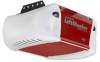
3850 Elite Series Manual
Page 2
...add, reprogram or change a Keyless Entry PIN 35 Repair Parts 36-37 Rail assembly parts 36 Installation parts 36 Motor unit assembly parts 37 Accessories 38 Notes 39 Repair Parts and Service 40 Warranty 40 INTRODUCTION Safety Symbol and Signal... word review 2 Preparing your garage door 3 Tools needed 3 Planning 4 Carton inventory 5 Hardware inventory 5 Assembly 6-7 Attach the rail to the motor unit 6 Set the belt tension 6 Attach the belt cap retainer 7 Installation 7-22 Installation safety instructions 7 Determine the header bracket location 8 Install...
...add, reprogram or change a Keyless Entry PIN 35 Repair Parts 36-37 Rail assembly parts 36 Installation parts 36 Motor unit assembly parts 37 Accessories 38 Notes 39 Repair Parts and Service 40 Warranty 40 INTRODUCTION Safety Symbol and Signal... word review 2 Preparing your garage door 3 Tools needed 3 Planning 4 Carton inventory 5 Hardware inventory 5 Assembly 6-7 Attach the rail to the motor unit 6 Set the belt tension 6 Attach the belt cap retainer 7 Installation 7-22 Installation safety instructions 7 Determine the header bracket location 8 Install...
3850 Elite Series Manual
Page 4
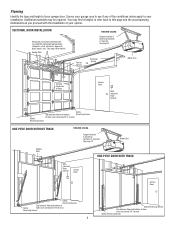
.... See page 12. You may be required. Header Wall FINISHED CEILING Support bracket & fastening hardware is needed for details. Motor Unit Header Wall ONE-PIECE DOOR WITH TRACK Wallmounted Door Control Access Door Access Door Safety Reversing Sensor Gap between floor and ... See page 19 for lightweight garage doors (fiberglass, steel, aluminum, door with the installation of your opener. Torsion Spring Extension Spring OR Motor Unit --- --- -- Safety Reversing Sensor Planning Identify the type and height of your installation. Survey your garage area to your garage door....
.... See page 12. You may be required. Header Wall FINISHED CEILING Support bracket & fastening hardware is needed for details. Motor Unit Header Wall ONE-PIECE DOOR WITH TRACK Wallmounted Door Control Access Door Access Door Safety Reversing Sensor Gap between floor and ... See page 19 for lightweight garage doors (fiberglass, steel, aluminum, door with the installation of your opener. Torsion Spring Extension Spring OR Motor Unit --- --- -- Safety Reversing Sensor Planning Identify the type and height of your installation. Survey your garage area to your garage door....
3850 Elite Series Manual
Page 5
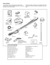
... the packing material. If anything is also listed below . Parts may be stuck in two cartons which contain the motor unit and all parts illustrated below . Accessories will depend on the model purchased. Carton Inventory Your garage door opener is.... LOCK LIGHT SLmCaDrtMCootniotrnolDPeatencetli®ng Door Control Console SECURITY✚® 3-Button Remote Control Models 3850 (1) 3850-267 (2) SECURITY✚® Keyless Entry Model 3850-267 (1) ONLY Motor Unit with Light Lenses 2-Conductor Bell Wire White & White/Red Belt Pulley Bracket Trolley Optional ...
... the packing material. If anything is also listed below . Parts may be stuck in two cartons which contain the motor unit and all parts illustrated below . Accessories will depend on the model purchased. Carton Inventory Your garage door opener is.... LOCK LIGHT SLmCaDrtMCootniotrnolDPeatencetli®ng Door Control Console SECURITY✚® 3-Button Remote Control Models 3850 (1) 3850-267 (2) SECURITY✚® Keyless Entry Model 3850-267 (1) ONLY Motor Unit with Light Lenses 2-Conductor Bell Wire White & White/Red Belt Pulley Bracket Trolley Optional ...
3850 Elite Series Manual
Page 6
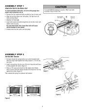
...to do not run the garage door opener until it firmly against the trolley (Figure 2). • Place a 7/16" open end wrench on top of motor unit. This extends the spring for optimum belt tension. Use only these bolts! Tighten bolts securely. Washered Bolt 5/16"-18x1/2" Rail Hole USE ONLY THIS... TYPE AND SIZE BOLT Motor Unit Belt Pulley Rail Hole ASSEMBLY STEP 2 Set the Belt Tension • By hand, thread the spring trolley nut on the threaded shaft until ...
...to do not run the garage door opener until it firmly against the trolley (Figure 2). • Place a 7/16" open end wrench on top of motor unit. This extends the spring for optimum belt tension. Use only these bolts! Tighten bolts securely. Washered Bolt 5/16"-18x1/2" Rail Hole USE ONLY THIS... TYPE AND SIZE BOLT Motor Unit Belt Pulley Rail Hole ASSEMBLY STEP 2 Set the Belt Tension • By hand, thread the spring trolley nut on the threaded shaft until ...
3850 Elite Series Manual
Page 7
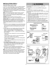
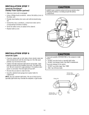
.... • SECURELY attach belt pulley cover BEFORE operating. 8x3/8" Hex Screws HARDWARE SHOWN ACTUAL SIZE Hex Screw #8x3/8" WARNING Belt Cap Retainer Motor Unit Belt Pulley Mounting Plate WARNING INSTALLATION IMPORTANT INSTALLATION INSTRUCTIONS WARNING To reduce the risk of garage door. 12. Place entrapment warning label on wall... hardware MUST be caught in mounting plate. ASSEMBLY STEP 3 Attach the Belt Cap Retainer • Position the belt cap retainer over the motor unit belt pulley so the three holes in cap align with the three holes in garage door or opener mechanisms. 9.
.... • SECURELY attach belt pulley cover BEFORE operating. 8x3/8" Hex Screws HARDWARE SHOWN ACTUAL SIZE Hex Screw #8x3/8" WARNING Belt Cap Retainer Motor Unit Belt Pulley Mounting Plate WARNING INSTALLATION IMPORTANT INSTALLATION INSTRUCTIONS WARNING To reduce the risk of garage door. 12. Place entrapment warning label on wall... hardware MUST be caught in mounting plate. ASSEMBLY STEP 3 Attach the Belt Cap Retainer • Position the belt cap retainer over the motor unit belt pulley so the three holes in cap align with the three holes in garage door or opener mechanisms. 9.
3850 Elite Series Manual
Page 11
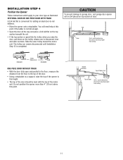
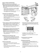
... the door. • Using a stepladder as illustrated. Do not position the opener more than 4" (10 cm) above this point. Header Bracket Top of Motor Unit Top of Door 2x4 is used to -rail distance. • Raise the opener onto a stepladder. SECTIONAL DOOR OR ONE-PIECE DOOR WITH TRACK A ...2x4 laid flat is completed. Slide the outer trolley toward the motor unit. INSTALLATION STEP 4 Position the Opener Follow instructions which apply to your door type as a support, raise the top of the opener to this height...
... the door. • Using a stepladder as illustrated. Do not position the opener more than 4" (10 cm) above this point. Header Bracket Top of Motor Unit Top of Door 2x4 is used to -rail distance. • Raise the opener onto a stepladder. SECTIONAL DOOR OR ONE-PIECE DOOR WITH TRACK A ...2x4 laid flat is completed. Slide the outer trolley toward the motor unit. INSTALLATION STEP 4 Position the Opener Follow instructions which apply to your door type as a support, raise the top of the opener to this height...
3850 Elite Series Manual
Page 12
... Screws 5/16"-18x1-7/8" Figure 2 Bracket (Not Provided) Bolt 5/16"-18x7/8" Lock Washer 5/16" Nut 5/16"-18 Hidden Support - Grease the top and underside of the motor unit to a support with rail grease. Remove foam packaging. Fasten the opener to make sure the rail is not centered above the door). 7. Check to...
... Screws 5/16"-18x1-7/8" Figure 2 Bracket (Not Provided) Bolt 5/16"-18x7/8" Lock Washer 5/16" Nut 5/16"-18 Hidden Support - Grease the top and underside of the motor unit to a support with rail grease. Remove foam packaging. Fasten the opener to make sure the rail is not centered above the door). 7. Check to...
3850 Elite Series Manual
Page 13
... use the anchors provided. SPECIAL NOTE: Only one end of bell wire and connect to the two screw terminals on the motor unit: white to white and white/red to motor unit. HARDWARE SHOWN ACTUAL SIZE Screw 6ABx1-1/4" (standard installation) Insulated Staples Screw 6-32x1" (pre-wired) Drywall Anchors Figure 1 REMOVE COVER REPLACE...
... use the anchors provided. SPECIAL NOTE: Only one end of bell wire and connect to the two screw terminals on the motor unit: white to white and white/red to motor unit. HARDWARE SHOWN ACTUAL SIZE Screw 6ABx1-1/4" (standard installation) Insulated Staples Screw 6-32x1" (pre-wired) Drywall Anchors Figure 1 REMOVE COVER REPLACE...
3850 Elite Series Manual
Page 14
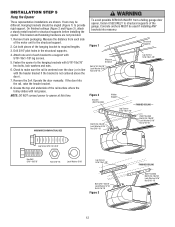
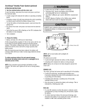
... lens hinge is unplugged. • Using a Phillips head screwdriver, remove the battery cover on the motor unit. • Partially insert battery into motor unit with terminals facing out. • Connect the red (+) and black (-) wires from motor unit to corresponding terminals on both sides of short neck or speciality light bulbs may overheat... the battery wires are seated in the channel. • Replace battery cover. INSTALLATION STEP 7 Install the EverCharge® Standby Power System (optional) • Make sure motor unit is in the fully open position.
... lens hinge is unplugged. • Using a Phillips head screwdriver, remove the battery cover on the motor unit. • Partially insert battery into motor unit with terminals facing out. • Connect the red (+) and black (-) wires from motor unit to corresponding terminals on both sides of short neck or speciality light bulbs may overheat... the battery wires are seated in the channel. • Replace battery cover. INSTALLATION STEP 7 Install the EverCharge® Standby Power System (optional) • Make sure motor unit is in the fully open position.
3850 Elite Series Manual
Page 15
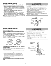
... the handle is 6 feet (1.8 m) above the floor. Secure with a third grounding pin. Ensure that the rope and handle clear the tops of the motor unit: • Remove the motor unit cover screws and set the cover aside. • Remove the attached 3-prong cord. • Connect the black (line) wire to the screw...
... the handle is 6 feet (1.8 m) above the floor. Secure with a third grounding pin. Ensure that the rope and handle clear the tops of the motor unit: • Remove the motor unit cover screws and set the cover aside. • Remove the attached 3-prong cord. • Connect the black (line) wire to the screw...

3850 Elite Series Manual
Page 22
... trolley lockout feature on page 27. • When setting the up limit on the emergency release handle and sliding the outer trolley back toward the motor unit. • Connect the curved door arm section to the trolley using the 5/16"x1-1/4" clevis pin and ring fastener. Figure 4 Door Bracket Clevis Pin...
... trolley lockout feature on page 27. • When setting the up limit on the emergency release handle and sliding the outer trolley back toward the motor unit. • Connect the curved door arm section to the trolley using the 5/16"x1-1/4" clevis pin and ring fastener. Figure 4 Door Bracket Clevis Pin...
3850 Elite Series Manual
Page 27
... the timer is in motion. However, the door will also turn it on for five minutes, then shut off whenever the "learn" button on the motor unit panel is equipped with a PROG button to assist in front of the door control. Press Learn Button Again to Learn Remote.' Press Remote Control...
... the timer is in motion. However, the door will also turn it on for five minutes, then shut off whenever the "learn" button on the motor unit panel is equipped with a PROG button to assist in front of the door control. Press Learn Button Again to Learn Remote.' Press Remote Control...
3850 Elite Series Manual
Page 29
...other extended period of battery in fire. EverCharge® Standby Power System (optional) OPERATING INSTRUCTIONS 1. To test the battery, disconnect the motor unit power cord from the electrical outlet. • A solid orange LED indicates the battery is operating on battery power. •...Battery do not have to operate the motor unit. A fully charged battery supplies 12 Vdc to the motor unit for one to persons: • Disconnect ALL electric and battery power BEFORE performing ANY service or maintenance. • Use ONLY LiftMaster part number 485LM for disposal instructions....
...other extended period of battery in fire. EverCharge® Standby Power System (optional) OPERATING INSTRUCTIONS 1. To test the battery, disconnect the motor unit power cord from the electrical outlet. • A solid orange LED indicates the battery is operating on battery power. •...Battery do not have to operate the motor unit. A fully charged battery supplies 12 Vdc to the motor unit for one to persons: • Disconnect ALL electric and battery power BEFORE performing ANY service or maintenance. • Use ONLY LiftMaster part number 485LM for disposal instructions....
3850 Elite Series Manual
Page 31
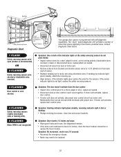
... for occasional adjustment for the force and limit settings is normal. Trolley 4. Refer to troubleshooting. 1. Bell Wire Diagnostics Located On Motor Unit Safety Reversing Sensor Sending Eye Safety Reversing Sensor (Amber Indicator Light) "Learn" Button LED or Diagnostic LED Receiving Eye Safety ...the battery. 31 The need for occasional adjustment for the force and limit settings is normal. My door reverses for flashes on motor unit then refer to disengage. Weather conditions in the down travel limits. Having a Problem (Troubleshooting) NOTE: Always unplug battery prior...
... for occasional adjustment for the force and limit settings is normal. Trolley 4. Refer to troubleshooting. 1. Bell Wire Diagnostics Located On Motor Unit Safety Reversing Sensor Sending Eye Safety Reversing Sensor (Amber Indicator Light) "Learn" Button LED or Diagnostic LED Receiving Eye Safety ...the battery. 31 The need for occasional adjustment for the force and limit settings is normal. My door reverses for flashes on motor unit then refer to disengage. Weather conditions in the down travel limits. Having a Problem (Troubleshooting) NOTE: Always unplug battery prior...
3850 Elite Series Manual
Page 32
...or replace the travel module. Symptom: One or both of sensor. • Reattach sending eye to 1-2 ft (30-60 cm) from motor unit. Symptom: Sending indicator light glows steadily, receiving indicator light is dim or flashing. • Realign receiving eye sensor, clean lens and...replace as needed . • Disconnect wires at door control, touch wires together. Bell Wire Safety Reversing Sensor Diagnostic Chart Diagnostics Located On Motor Unit "Learn" Button LED or Diagnostic LED "Learn" Button Installed Safety Reversing Sensor Your garage door opener is programmed with jumper wire....
...or replace the travel module. Symptom: One or both of sensor. • Reattach sending eye to 1-2 ft (30-60 cm) from motor unit. Symptom: Sending indicator light glows steadily, receiving indicator light is dim or flashing. • Realign receiving eye sensor, clean lens and...replace as needed . • Disconnect wires at door control, touch wires together. Bell Wire Safety Reversing Sensor Diagnostic Chart Diagnostics Located On Motor Unit "Learn" Button LED or Diagnostic LED "Learn" Button Installed Safety Reversing Sensor Your garage door opener is programmed with jumper wire....
3850 Elite Series Manual
Page 33
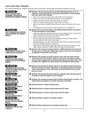
... short (staple in wire), correct wiring polarity (black/white wires reversed), replace/attach as needed. • Disconnect all wires from back of motor unit. • Remove safety reversing sensors from brackets and shorten sensor wires to the opener. Message LOCK MODE REMOTE CONTROL LOCKED OUT PRESS LOCK ...backup state. 33 Meaning: This message will appear if the Safety Reversing Sensors are out of alignment, if they are connected to the motor unit. • If message has not cleared after the above checks, refer to program another remote control by simply pressing the remote control...
... short (staple in wire), correct wiring polarity (black/white wires reversed), replace/attach as needed. • Disconnect all wires from back of motor unit. • Remove safety reversing sensors from brackets and shorten sensor wires to the opener. Message LOCK MODE REMOTE CONTROL LOCKED OUT PRESS LOCK ...backup state. 33 Meaning: This message will appear if the Safety Reversing Sensors are out of alignment, if they are connected to the motor unit. • If message has not cleared after the above checks, refer to program another remote control by simply pressing the remote control...
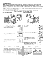
3850 Elite Series Manual
Page 34
... are not installed, two clicks will be programmed to operate other Security✚® garage door openers. 34 To Erase All Codes From Motor Unit Memory To deactivate any Security✚® 3-button remote or mini-remote can be heard. *3-Button Remotes (315 MHz) If provided...learned the code. Within 30 seconds, press and hold the "learn indicator light goes out (approximately 6 seconds). Release the button when the motor unit lights blink. Press the PROG button on the hand-held Remote Control USING THE DOOR CONTROL LOCK LIGHT LOCK LIGHT 1. LOCK LIGHT LOCK...
... are not installed, two clicks will be programmed to operate other Security✚® garage door openers. 34 To Erase All Codes From Motor Unit Memory To deactivate any Security✚® 3-button remote or mini-remote can be heard. *3-Button Remotes (315 MHz) If provided...learned the code. Within 30 seconds, press and hold the "learn indicator light goes out (approximately 6 seconds). Release the button when the motor unit lights blink. Press the PROG button on the hand-held Remote Control USING THE DOOR CONTROL LOCK LIGHT LOCK LIGHT 1. LOCK LIGHT LOCK...
3850 Elite Series Manual
Page 35
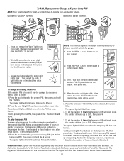
... password, repeat steps 1-3, setting the number of your choice on the keypad. Press the new 4-digit PIN you have chosen, then press Enter. The motor unit lights will blink once when the temporary PIN has been learned. The opener light will blink once when the PIN has been learned. The... keypad will blink four times when one button close is active. Press the PROG button on motor unit. Enter a four digit personal identification number (PIN) of hours or times to 255), then press ✽. Press the four buttons for your ...
... password, repeat steps 1-3, setting the number of your choice on the keypad. Press the new 4-digit PIN you have chosen, then press Enter. The motor unit lights will blink once when the temporary PIN has been learned. The opener light will blink once when the PIN has been learned. The... keypad will blink four times when one button close is active. Press the PROG button on motor unit. Enter a four digit personal identification number (PIN) of hours or times to 255), then press ✽. Press the four buttons for your ...
3850 Elite Series Manual
Page 37
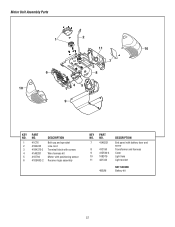
DESCRIPTION 1 41C76 Belt cap and sprocket 2 41B4245 Line cord 3 41B4375-3 Terminal block with screws 4 41A6281 Wire harness kit 5 41D794 Motor with battery door and screw Transformer and harness Cover Light lens Light socket NOT SHOWN Battery kit 37 NO. 7 41A6231 8 41C190 9 41D504-4 10 108D79 11 4A1344 485LM DESCRIPTION End panel with positioning sensor 6 41DB002-2 Receiver logic assembly KEY PART NO. NO. Motor Unit Assembly Parts 1 2 11 10 7 3 6 8 45 10 9 KEY PART NO.
DESCRIPTION 1 41C76 Belt cap and sprocket 2 41B4245 Line cord 3 41B4375-3 Terminal block with screws 4 41A6281 Wire harness kit 5 41D794 Motor with battery door and screw Transformer and harness Cover Light lens Light socket NOT SHOWN Battery kit 37 NO. 7 41A6231 8 41C190 9 41D504-4 10 108D79 11 4A1344 485LM DESCRIPTION End panel with positioning sensor 6 41DB002-2 Receiver logic assembly KEY PART NO. NO. Motor Unit Assembly Parts 1 2 11 10 7 3 6 8 45 10 9 KEY PART NO.
3850 Elite Series Manual
Page 40
... Yellow Pages, or call . Country Club Road Tucson, Arizona 85706 SERVICE INFORMATION TOLL FREE NUMBER: 1-800-528-9131 LIFTMASTER FIVE YEAR LIMITED WARRANTY LIFETIME MOTOR AND BELT LIMITED WARRANTY ONE YEAR LIMITED WARRANTY FOR EVERCHARGE® STANDBY POWER BATTERY The Chamberlain Group, Inc. ("Seller")..., OR INABILITY TO USE, THIS PRODUCT. Defective parts will be repaired or replaced with those instructions will be billed accordingly. LIFTMASTER® SERVICE IS ON CALL OUR LARGE SERVICE ORGANIZATION SPANS AMERICA INSTALLATION AND SERVICE INFORMATION IS AS NEAR AS YOUR TELEPHONE. ...
... Yellow Pages, or call . Country Club Road Tucson, Arizona 85706 SERVICE INFORMATION TOLL FREE NUMBER: 1-800-528-9131 LIFTMASTER FIVE YEAR LIMITED WARRANTY LIFETIME MOTOR AND BELT LIMITED WARRANTY ONE YEAR LIMITED WARRANTY FOR EVERCHARGE® STANDBY POWER BATTERY The Chamberlain Group, Inc. ("Seller")..., OR INABILITY TO USE, THIS PRODUCT. Defective parts will be repaired or replaced with those instructions will be billed accordingly. LIFTMASTER® SERVICE IS ON CALL OUR LARGE SERVICE ORGANIZATION SPANS AMERICA INSTALLATION AND SERVICE INFORMATION IS AS NEAR AS YOUR TELEPHONE. ...


