

3240 Manual
Page 1
® GARAGE DOOR OPENER Models The Chamberlain Group, Inc. 845 Larch Avenue Elmhurst, Illinois 60126-1196 www.liftmaster.com 3130M 1/3 HP For Residential Use Only 3240M 1/2 HP Owner's Manual ■ Please read this manual and the enclosed safety materials carefully! ■ Fasten the manual near the garage door after installation. ■ The door WILL NOT CLOSE unless the Protector System® is connected and properly aligned. ■ Periodic checks of the opener are required to ensure safe operation. ■ The model number label is located on the front panel of your opener.
® GARAGE DOOR OPENER Models The Chamberlain Group, Inc. 845 Larch Avenue Elmhurst, Illinois 60126-1196 www.liftmaster.com 3130M 1/3 HP For Residential Use Only 3240M 1/2 HP Owner's Manual ■ Please read this manual and the enclosed safety materials carefully! ■ Fasten the manual near the garage door after installation. ■ The door WILL NOT CLOSE unless the Protector System® is connected and properly aligned. ■ Periodic checks of the opener are required to ensure safe operation. ■ The model number label is located on the front panel of your opener.
3240 Manual
Page 2
...location 8 Install the header bracket 9 Attach the rail to the header bracket 10 Install the Protector System 11-13 Position the opener 14 Hang the opener 15 Install the door control 16 Install the lights 17 Attach the emergency release rope and handle 17 Electrical requirements 18 Complete ... force 24 Test the safety reversal system 25 Test the Protector System 25 Operation 26-30 Operation safety instructions 26 Using your garage door opener 28 Having a problem 29 Diagnostic chart 30 Programming 31-32 To add or reprogram a hand-held remote control 31 To erase all ...
...location 8 Install the header bracket 9 Attach the rail to the header bracket 10 Install the Protector System 11-13 Position the opener 14 Hang the opener 15 Install the door control 16 Install the lights 17 Attach the emergency release rope and handle 17 Electrical requirements 18 Complete ... force 24 Test the safety reversal system 25 Test the Protector System 25 Operation 26-30 Operation safety instructions 26 Using your garage door opener 28 Having a problem 29 Diagnostic chart 30 Programming 31-32 To add or reprogram a hand-held remote control 31 To erase all ...

3240 Manual
Page 3
.... An unbalanced garage door may NOT reverse when required. • NEVER try to make sure your door binds, sticks, or is out of the opener, instructions will call a trained door systems technician if garage door binds, sticks, or is not sticking or binding: 1. If balanced, it should stay... are under EXTREME tension. • Disable ALL locks and remove ALL ropes connected to garage door BEFORE installing and operating garage door opener to avoid malfunction and damage. Preparing your garage door Before you begin: • Disable locks. • Remove any binding or sticking.
.... An unbalanced garage door may NOT reverse when required. • NEVER try to make sure your door binds, sticks, or is out of the opener, instructions will call a trained door systems technician if garage door binds, sticks, or is not sticking or binding: 1. If balanced, it should stay... are under EXTREME tension. • Disable ALL locks and remove ALL ropes connected to garage door BEFORE installing and operating garage door opener to avoid malfunction and damage. Preparing your garage door Before you begin: • Disable locks. • Remove any binding or sticking.
3240 Manual
Page 4
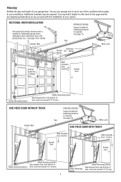
... Identify the type and height of Garage Door Wallmounted Door Control Access Door --- --- -- Additional materials may find it helpful to refer back to your opener. SECTIONAL DOOR INSTALLATION Horizontal and vertical reinforcement is required. Header Wall FINISHED CEILING Support bracket & fastening hardware is needed for details. See page 16. Rail...
... Identify the type and height of Garage Door Wallmounted Door Control Access Door --- --- -- Additional materials may find it helpful to refer back to your opener. SECTIONAL DOOR INSTALLATION Horizontal and vertical reinforcement is required. Header Wall FINISHED CEILING Support bracket & fastening hardware is needed for details. See page 16. Rail...
3240 Manual
Page 5
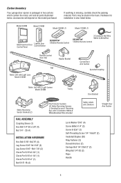
Carton Inventory Your garage door opener is packaged in the foam. Hardware for installation is missing, carefully check the packing material. Model 3240M Model 3130M Model 3240M (1) Model 3130M (1) Multi-Function ...
Carton Inventory Your garage door opener is packaged in the foam. Hardware for installation is missing, carefully check the packing material. Model 3240M Model 3130M Model 3240M (1) Model 3130M (1) Multi-Function ...
3240 Manual
Page 6
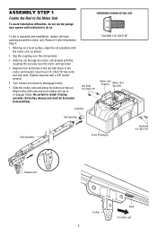
...; Slip the coupling over the rail sprocket. • Slide the rail through the motor unit bracket until instructed to do not run the garage door opener until the coupling fits securely over the motor unit sprocket. • Align the two bolt holes in assembly and installation, replace the foam packing...
...; Slip the coupling over the rail sprocket. • Slide the rail through the motor unit bracket until instructed to do not run the garage door opener until the coupling fits securely over the motor unit sprocket. • Align the two bolt holes in assembly and installation, replace the foam packing...

3240 Manual
Page 7
...door. Place entrapment warning label on wall next to avoid entanglement. 5. NEVER wear watches, rings or loose clothing while installing or servicing opener. Upon completion of garage door. 12. Install wall-mounted garage door control: • within sight of the garage door. •... INSTRUCTIONS WARNING To reduce the risk of the door. 10. READ AND FOLLOW ALL INSTALLATION WARNINGS AND INSTRUCTIONS. 2. Install garage door opener ONLY on inside of installation, test safety reversal system. An improperly balanced door may NOT reverse when required and could be made by...
...door. Place entrapment warning label on wall next to avoid entanglement. 5. NEVER wear watches, rings or loose clothing while installing or servicing opener. Upon completion of garage door. 12. Install wall-mounted garage door control: • within sight of the garage door. •... INSTRUCTIONS WARNING To reduce the risk of the door. 10. READ AND FOLLOW ALL INSTALLATION WARNINGS AND INSTRUCTIONS. 2. Install garage door opener ONLY on inside of installation, test safety reversal system. An improperly balanced door may NOT reverse when required and could be made by...

3240 Manual
Page 8
... m) of the left or right of the door center only if a torsion spring or center bearing plate is minimal. (It may be mounted on page 9. 3. Open your door to the highest point of the door. This height will provide travel clearance for the top edge of travel as shown here and...
... m) of the left or right of the door center only if a torsion spring or center bearing plate is minimal. (It may be mounted on page 9. 3. Open your door to the highest point of the door. This height will provide travel clearance for the top edge of travel as shown here and...

3240 Manual
Page 10
...is in the way you'll need help. Garage Door Rail Ring Fastener Header Bracket Clevis Pin 5/16"x2-3/4" Spacer Rail Bracket Rail Spacer Opener Carton or Temporary Support HARDWARE SHOWN ACTUAL SIZE Clevis Pin 5/16"x2-3/4" Ring Fastener 10 Spacer Have someone hold the... opener securely on the garage floor below the header bracket. Header Wall Header Bracket Rail Bracket INSTALLATION STEP 3 Attach the Rail to the Header Bracket • Position the opener on a temporary support to allow the rail to secure.
...is in the way you'll need help. Garage Door Rail Ring Fastener Header Bracket Clevis Pin 5/16"x2-3/4" Spacer Rail Bracket Rail Spacer Opener Carton or Temporary Support HARDWARE SHOWN ACTUAL SIZE Clevis Pin 5/16"x2-3/4" Ring Fastener 10 Spacer Have someone hold the... opener securely on the garage floor below the header bracket. Header Wall Header Bracket Rail Bracket INSTALLATION STEP 3 Attach the Rail to the Header Bracket • Position the opener on a temporary support to allow the rail to secure.

3240 Manual
Page 11
... no more than 6" (15 cm) above floor Facing the door from a closing , the door will stop and reverse to full open position, and the opener lights will detect an obstacle in masonry construction, add a piece of its electronic beam. IMPORTANT INFORMATION ABOUT THE SAFETY REVERSING SENSOR When properly... the floor. Either can be installed on the wall, the brackets must be connected and aligned correctly before the garage door opener will move in masonry if repositioning is necessary to mount the units on the left or right of sectional garage doors without additional hardware...
... no more than 6" (15 cm) above floor Facing the door from a closing , the door will stop and reverse to full open position, and the opener lights will detect an obstacle in masonry construction, add a piece of its electronic beam. IMPORTANT INFORMATION ABOUT THE SAFETY REVERSING SENSOR When properly... the floor. Either can be installed on the wall, the brackets must be connected and aligned correctly before the garage door opener will move in masonry if repositioning is necessary to mount the units on the left or right of sectional garage doors without additional hardware...
3240 Manual
Page 12
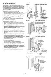
... Track Lip DOOR TRACK MOUNT (RIGHT SIDE) Indicator Light Safety Reversing Sensor Lens Bracket Figure 2 Figure 3 WALL MOUNT (RIGHT SIDE) Fasten Wood Block to the opener is recommended. Install and align the brackets so the sensors will not support the bracket securely, wall installation is disconnected.
... Track Lip DOOR TRACK MOUNT (RIGHT SIDE) Indicator Light Safety Reversing Sensor Lens Bracket Figure 2 Figure 3 WALL MOUNT (RIGHT SIDE) Fasten Wood Block to the opener is recommended. Install and align the brackets so the sensors will not support the bracket securely, wall installation is disconnected.
3240 Manual
Page 14
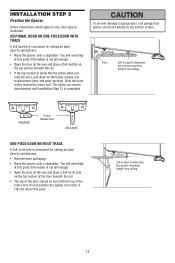
... sections. You will need help at this point if the ladder is convenient for setting an ideal door-to garage door, rest garage door opener rail on 2x4 placed on the top section of the door beneath the rail. • The top of the door should be level with...is used to determine the correct mounting height from ceiling. 14 To prevent damage to -rail distance. • Remove foam packaging. • Raise the opener onto a stepladder. ENGAGED Trolley Release Arm RELEASED ONE-PIECE DOOR WITHOUT TRACK A 2x4 on the trolley release arm to determine the correct mounting height from...
... sections. You will need help at this point if the ladder is convenient for setting an ideal door-to garage door, rest garage door opener rail on 2x4 placed on the top section of the door beneath the rail. • The top of the door should be level with...is used to determine the correct mounting height from ceiling. 14 To prevent damage to -rail distance. • Remove foam packaging. • Raise the opener onto a stepladder. ENGAGED Trolley Release Arm RELEASED ONE-PIECE DOOR WITHOUT TRACK A 2x4 on the trolley release arm to determine the correct mounting height from...
3240 Manual
Page 15
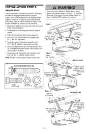
...To avoid possible SERIOUS INJURY from each side of each bracket to structural supports before installing the opener. Hanging brackets should be angled (Figure 1) to opener at this time. Fasten the opener to required lengths. 3. If the door hits the rail, raise the header bracket. This ..."-18x7/8" Lock Washer 5/16" Nut 5/16"-18 15 Check to the structural support. 2. Measure the distance from a falling garage door opener, fasten it SECURELY to structural supports of the hanging bracket to the hanging brackets with the header bracket if the bracket is centered over ...
...To avoid possible SERIOUS INJURY from each side of each bracket to structural supports before installing the opener. Hanging brackets should be angled (Figure 1) to opener at this time. Fasten the opener to required lengths. 3. If the door hits the rail, raise the header bracket. This ..."-18x7/8" Lock Washer 5/16" Nut 5/16"-18 15 Check to the structural support. 2. Measure the distance from a falling garage door opener, fasten it SECURELY to structural supports of the hanging bracket to the hanging brackets with the header bracket if the bracket is centered over ...

3240 Manual
Page 16
... First Figure 4 24 Volt Bell Wire 9 1 7 3 5 KG 9 1 7 3 5 KG NOTE: When connecting multiple door controls to the opener quick-connect terminals. Multi-function: Remove white cover by color: white wire to white, white/red wire to cross path of the door and door...installation) 6ABx1-1/4" Screw Multi-Function (pre-wired) Screw 6-32x1" Figure 1 STANDARD INSTALLATION Figure 2 PRE-WIRED INSTALLATION a staple, creating a short or open position but will not return to the 1 (Figure 3). 2. DO NOT overtighten. • Insert bottom tabs and snap on a smooth surface. Insert ...
... First Figure 4 24 Volt Bell Wire 9 1 7 3 5 KG 9 1 7 3 5 KG NOTE: When connecting multiple door controls to the opener quick-connect terminals. Multi-function: Remove white cover by color: white wire to white, white/red wire to cross path of the door and door...installation) 6ABx1-1/4" Screw Multi-Function (pre-wired) Screw 6-32x1" Figure 1 STANDARD INSTALLATION Figure 2 PRE-WIRED INSTALLATION a staple, creating a short or open position but will not return to the 1 (Figure 3). 2. DO NOT overtighten. • Insert bottom tabs and snap on a smooth surface. Insert ...

3240 Manual
Page 17
... bulbs. Secure with an overhand knot at least 1" (2.5 cm) from a falling garage door: • If possible, use emergency release handle to the opener: • DO NOT use bulbs larger than 100W. • ONLY use handle to prevent unraveling. To prevent possible SERIOUS INJURY or DEATH from the end...handle so "NOTICE" reads right side up as shown. Do not remove the lens. • Install a 100 watt maximum light bulb in the fully open door falling rapidly and/or unexpectedly. • NEVER use emergency release handle unless garage doorway is 6 feet (1.83 m) above the floor. Use...
... bulbs. Secure with an overhand knot at least 1" (2.5 cm) from a falling garage door: • If possible, use emergency release handle to the opener: • DO NOT use bulbs larger than 100W. • ONLY use handle to prevent unraveling. To prevent possible SERIOUS INJURY or DEATH from the end...handle so "NOTICE" reads right side up as shown. Do not remove the lens. • Install a 100 watt maximum light bulb in the fully open door falling rapidly and/or unexpectedly. • NEVER use emergency release handle unless garage doorway is 6 feet (1.83 m) above the floor. Use...

3240 Manual
Page 18
...the proper outlet. TROUBLESHOOTING THE SAFETY REVERSING SENSORS 1. If the sending eye indicator light does not glow steadily after installation, check for an open , it fit outlet. NOTE: When the invisible beam path is obstructed or misaligned while the door is grounded. If the plug ... See page 11. 18 INSTALLATION STEP 10 Electrical Requirements To avoid installation difficulties, do not run the opener at opener connections. • Incorrect wiring between sensors and opener. • A broken wire. 2. This plug will blink 10 times. (If bulbs are correct. To make...
...the proper outlet. TROUBLESHOOTING THE SAFETY REVERSING SENSORS 1. If the sending eye indicator light does not glow steadily after installation, check for an open , it fit outlet. NOTE: When the invisible beam path is obstructed or misaligned while the door is grounded. If the plug ... See page 11. 18 INSTALLATION STEP 10 Electrical Requirements To avoid installation difficulties, do not run the opener at opener connections. • Incorrect wiring between sensors and opener. • A broken wire. 2. This plug will blink 10 times. (If bulbs are correct. To make...

3240 Manual
Page 19
... best solution is to check with 5/16"x2" carriage bolts, lock washers and nuts (not provided) (Figure 4). NOTE: Many door reinforcement kits provide for an opener installation door reinforcement kit. Position the top edge of the bracket 2"-4" (5-10 cm) below the top edge of the door, OR directly below or on...
... best solution is to check with 5/16"x2" carriage bolts, lock washers and nuts (not provided) (Figure 4). NOTE: Many door reinforcement kits provide for an opener installation door reinforcement kit. Position the top edge of the bracket 2"-4" (5-10 cm) below the top edge of the door, OR directly below or on...

3240 Manual
Page 21
... door arm rigidity. • Figure 3, Hole alignment alternative: - Secure the connection with bolts, lock washers and nuts. • Pull the emergency release handle toward the opener at a 45° angle so that line up and join with a ring fastener. - Bring arm sections together. Slide the outer trolley back (away from the... door arm (Figure 4). • Figure 2: - SECTIONAL DOORS ONLY • Make sure garage door is operated. Bring arm sections together. - Trolley will re-engage automatically when opener is fully closed.
... door arm rigidity. • Figure 3, Hole alignment alternative: - Secure the connection with bolts, lock washers and nuts. • Pull the emergency release handle toward the opener at a 45° angle so that line up and join with a ring fastener. - Bring arm sections together. Slide the outer trolley back (away from the... door arm (Figure 4). • Figure 2: - SECTIONAL DOORS ONLY • Make sure garage door is operated. Bring arm sections together. - Trolley will re-engage automatically when opener is fully closed.

3240 Manual
Page 22
...the door arm connector hole. Turn the UP limit adjustment screw counterclockwise 4 turns. - If the door has a slight "backward" slant in full open trolley/door arm positions in the illustration. The trolley will travel to make the connection. • Secure with a ring fastener. 2. Adjustment procedures,...door arm to the trolley, the travel cycle. Closed Door Emergency Release Handle Inner Trolley Outer Trolley Correct Angle Door Arm Connector Hole Open Door 22 Door with a 2 or 3 hole overlap). • With the door closed, connect the straight door arm section to...
...the door arm connector hole. Turn the UP limit adjustment screw counterclockwise 4 turns. - If the door has a slight "backward" slant in full open trolley/door arm positions in the illustration. The trolley will travel to make the connection. • Secure with a ring fastener. 2. Adjustment procedures,...door arm to the trolley, the travel cycle. Closed Door Emergency Release Handle Inner Trolley Outer Trolley Correct Angle Door Arm Connector Hole Open Door 22 Door with a 2 or 3 hole overlap). • With the door closed, connect the straight door arm section to...

3240 Manual
Page 23
...as explained in fully closed ? Door MUST reverse on floor. HOW AND WHEN TO ADJUST THE LIMITS • If the door does not open completely but opens at least 5 feet (1.5 m): Increase up or down. One turn equals 2" (5 cm) of 2-4" (5-10 m) between the trolley and the...: Increase down limit adjustment screw counterclockwise. Without a properly installed safety reversal system, persons (particularly small children) could be sure fully open and close the door. ADJUSTMENT STEP 1 Adjust the UP and DOWN Travel Limits Limit adjustment settings regulate the points at which the ...
...as explained in fully closed ? Door MUST reverse on floor. HOW AND WHEN TO ADJUST THE LIMITS • If the door does not open completely but opens at least 5 feet (1.5 m): Increase up or down. One turn equals 2" (5 cm) of 2-4" (5-10 m) between the trolley and the...: Increase down limit adjustment screw counterclockwise. Without a properly installed safety reversal system, persons (particularly small children) could be sure fully open and close the door. ADJUSTMENT STEP 1 Adjust the UP and DOWN Travel Limits Limit adjustment settings regulate the points at which the ...


