
3240 Manual
Page 2
...symbol and signal word review 2 Preparing your garage door 3 Tools needed 3 Planning 4 Carton inventory 5 Hardware inventory 5 Assembly 6 Fasten rail to the motor unit 6 Installation 7-22 Installation safety instructions 7 Determine the header bracket location 8 Install the header bracket 9 Attach the...31 3-Button remotes 31 To add, reprogram or change a Keyless Entry PIN . . . . . 32 Repair Parts 33-34 Rail assembly parts 33 Installation parts 33 Motor unit assembly parts 34 Accessories 35 Repair Parts and Service Back page Warranty Back page INTRODUCTION ...
...symbol and signal word review 2 Preparing your garage door 3 Tools needed 3 Planning 4 Carton inventory 5 Hardware inventory 5 Assembly 6 Fasten rail to the motor unit 6 Installation 7-22 Installation safety instructions 7 Determine the header bracket location 8 Install the header bracket 9 Attach the...31 3-Button remotes 31 To add, reprogram or change a Keyless Entry PIN . . . . . 32 Repair Parts 33-34 Rail assembly parts 33 Installation parts 33 Motor unit assembly parts 34 Accessories 35 Repair Parts and Service Back page Warranty Back page INTRODUCTION ...
3240 Manual
Page 4
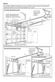
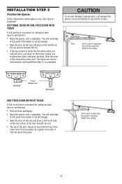
...is required. Safety Reversing Sensor Safety Reversing Sensor Gap between floor and bottom of door must not exceed 1/4" (6 mm). Rail Motor unit ONE-PIECE DOOR WITH TRACK Wall-mounted Door Control Access Door Wall-mounted Door Control Access Door Safety Reversing Sensor Gap...(6 mm). 4 Safety Reversing Sensor Safety Reversing Sensor Gap between floor and bottom of door must not exceed 1/4" (6 mm). Rail Extension Torsion OR Spring Spring Motor unit Vertical Centerline of the conditions below apply to your installation. Additional materials may find it ...
...is required. Safety Reversing Sensor Safety Reversing Sensor Gap between floor and bottom of door must not exceed 1/4" (6 mm). Rail Motor unit ONE-PIECE DOOR WITH TRACK Wall-mounted Door Control Access Door Wall-mounted Door Control Access Door Safety Reversing Sensor Gap...(6 mm). 4 Safety Reversing Sensor Safety Reversing Sensor Gap between floor and bottom of door must not exceed 1/4" (6 mm). Rail Extension Torsion OR Spring Spring Motor unit Vertical Centerline of the conditions below apply to your installation. Additional materials may find it ...
3240 Manual
Page 5
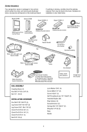
... SECURITY✚® White & White/Red 1-Button Remote Control CEILING MOUNT ONLY UP Remote Control Visor Clip Header Bracket Rail Curved Door Arm Section Sprocket Coupling Motor Unit with Light Lens Model 3130M Motor Unit with 2 Light Lenses Model 3240M ... Safety Reversing Sensors (1 Sending Eye and 1 Receiving Eye) with 2-Conductor White & White/Black Bell Wire attached Safety Labels and Literature Straight Door Arm Section RAIL ASSEMBLY Coupling Sleeve (1) Hex Bolt 1/4"-20 x 5/8" (4) Nut 1/4" - 20 (4) INSTALLATION HARDWARE Hex Bolt 5/16"-18x7/8" (4) Lag Screw 5/16"-9x1-5/8" ...
... SECURITY✚® White & White/Red 1-Button Remote Control CEILING MOUNT ONLY UP Remote Control Visor Clip Header Bracket Rail Curved Door Arm Section Sprocket Coupling Motor Unit with Light Lens Model 3130M Motor Unit with 2 Light Lenses Model 3240M ... Safety Reversing Sensors (1 Sending Eye and 1 Receiving Eye) with 2-Conductor White & White/Black Bell Wire attached Safety Labels and Literature Straight Door Arm Section RAIL ASSEMBLY Coupling Sleeve (1) Hex Bolt 1/4"-20 x 5/8" (4) Nut 1/4" - 20 (4) INSTALLATION HARDWARE Hex Bolt 5/16"-18x7/8" (4) Lag Screw 5/16"-9x1-5/8" ...
3240 Manual
Page 6
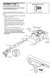
... a 3/8" socket wrench. • Turn release arm down to disengage trolley. • Slide the trolley onto and along the bottom of the rail. Remove it facing correctly: the trolley release arm must be horizontal (lock position). Tighten securely with those in the motor unit bracket. Hex Bolts 1/4"-...20x7/16" Hex Bolt 1/4"-20x7/16" Motor Unit Bracket Motor Unit Sprocket Coupling Rail Sprocket Rail Assembly Foam Packaging Hex Bolts 1/4"-20x7/16" Release Arm Trolley 6 Rack To motor unit ASSEMBLY STEP 1 Fasten the...
... a 3/8" socket wrench. • Turn release arm down to disengage trolley. • Slide the trolley onto and along the bottom of the rail. Remove it facing correctly: the trolley release arm must be horizontal (lock position). Tighten securely with those in the motor unit bracket. Hex Bolts 1/4"-...20x7/16" Hex Bolt 1/4"-20x7/16" Motor Unit Bracket Motor Unit Sprocket Coupling Rail Sprocket Rail Assembly Foam Packaging Hex Bolts 1/4"-20x7/16" Release Arm Trolley 6 Rack To motor unit ASSEMBLY STEP 1 Fasten the...

3240 Manual
Page 10
... SHOWN ACTUAL SIZE Clevis Pin 5/16"x2-3/4" Ring Fastener 10 Spacer Header Wall Header Bracket Rail Bracket INSTALLATION STEP 3 Attach the Rail to the Header Bracket • Position the opener on a temporary support to allow the rail to secure. Use packing material as shown. • Insert a ring fastener to clear ...the spring. • Position the rail bracket against the header bracket. • Align the bracket holes and join with a clevis pin as a protective base. Have someone hold the opener...
... SHOWN ACTUAL SIZE Clevis Pin 5/16"x2-3/4" Ring Fastener 10 Spacer Header Wall Header Bracket Rail Bracket INSTALLATION STEP 3 Attach the Rail to the Header Bracket • Position the opener on a temporary support to allow the rail to secure. Use packing material as shown. • Insert a ring fastener to clear ...the spring. • Position the rail bracket against the header bracket. • Align the bracket holes and join with a clevis pin as a protective base. Have someone hold the opener...

3240 Manual
Page 13
... nuts. Wing Nut Carriage Bolt 1/4"-20x1/2" Lens HARDWARE SHOWN ACTUAL SIZE Carriage Bolt 1/4"-20x1/2" Wing Nut 1/4"-20 Staples Figure 6 Sensor Wire Wire Clips Bell Wire Rail Safety Reversing Sensor Invisible Light Beam Protection Area Safety Reversing Sensor 13 Use wing nuts to fasten sensors to the... the wires through wire clips at the door header (Figure 6). 2. Using insulated staples, run the door control wire along the rail with lenses pointing toward each sensor. Be sure the lens is near the garage door, you may choose to install the door control at this ...
... nuts. Wing Nut Carriage Bolt 1/4"-20x1/2" Lens HARDWARE SHOWN ACTUAL SIZE Carriage Bolt 1/4"-20x1/2" Wing Nut 1/4"-20 Staples Figure 6 Sensor Wire Wire Clips Bell Wire Rail Safety Reversing Sensor Invisible Light Beam Protection Area Safety Reversing Sensor 13 Use wing nuts to fasten sensors to the... the wires through wire clips at the door header (Figure 6). 2. Using insulated staples, run the door control wire along the rail with lenses pointing toward each sensor. Be sure the lens is near the garage door, you may choose to install the door control at this ...
3240 Manual
Page 14
...the motor unit. Top of Door 2x4 is used to determine the correct mounting height from ceiling. Top of Door Door 2x4 is used to -rail distance. • Remove foam packaging. • Raise the opener onto a stepladder. The trolley can remain disconnected until Installation Step 13 is ... the correct mounting height from ceiling. 14 ENGAGED Trolley Release Arm RELEASED ONE-PIECE DOOR WITHOUT TRACK A 2x4 on the trolley release arm to -rail distance. • Raise the opener onto a stepladder. Do not position the opener more than 4" (10 cm) above this point if the ...
...the motor unit. Top of Door 2x4 is used to determine the correct mounting height from ceiling. Top of Door Door 2x4 is used to -rail distance. • Remove foam packaging. • Raise the opener onto a stepladder. The trolley can remain disconnected until Installation Step 13 is ... the correct mounting height from ceiling. 14 ENGAGED Trolley Release Arm RELEASED ONE-PIECE DOOR WITHOUT TRACK A 2x4 on the trolley release arm to -rail distance. • Raise the opener onto a stepladder. Do not position the opener more than 4" (10 cm) above this point if the ...
3240 Manual
Page 15
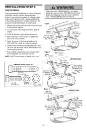
This bracket and fastening hardware are shown. Cut both pieces of the garage. If the door hits the rail, raise the header bracket. Yours may be angled (Figure 1) to the hanging brackets with the header bracket if the bracket is not centered above the ... brackets into masonry. Measure the distance from a falling garage door opener, fasten it SECURELY to structural supports of the hanging bracket to make sure the rail is centered over the door (or in the structural supports. 4. Attach one end of each side of the motor unit to a support with 5/16"-18x1...
This bracket and fastening hardware are shown. Cut both pieces of the garage. If the door hits the rail, raise the header bracket. Yours may be angled (Figure 1) to the hanging brackets with the header bracket if the bracket is not centered above the ... brackets into masonry. Measure the distance from a falling garage door opener, fasten it SECURELY to structural supports of the hanging bracket to make sure the rail is centered over the door (or in the structural supports. 4. Attach one end of each side of the motor unit to a support with 5/16"-18x1...

3240 Manual
Page 16
... power and operate the opener Lighted Door Control Multi-Function Door Control Door Control Connections To release or insert wire, push in top of the rail. If installing into quick-connect holes: white to white and white/black to motor unit. Multi-function: Remove white cover by gently prying at slot...
... power and operate the opener Lighted Door Control Multi-Function Door Control Door Control Connections To release or insert wire, push in top of the rail. If installing into quick-connect holes: white to white and white/black to motor unit. Multi-function: Remove white cover by gently prying at slot...

3240 Manual
Page 33
... (includes sprocket coupling) 2 81C275 Rack 3 41A6262 Complete trolley assembly 4 3077SD Screw Drive one-piece rail 7' (2.1 m) 5 3088SD Screw Drive one-piece rail 8' (2.4 m) 6 41A4836 Drive sprocket kit 7 25C20 Coupling 8 41A6312 Rail end bracket NOT SHOWN 28A143 Wire clips Installation Parts 3 1 2 4 5 6 6 7 8 ...9 10 11 CEILING MOUNT ONLY UP 12 14 13 KEY PART NO. REPAIR PARTS Rail Assembly Parts 5 3 6 1 7 2 4 KEY PART NO. NO. 1 41A5273-1 2 41A4166 3 41A2828 4 371LM 5 373LM 6 10A20 7 29B137 ...
... (includes sprocket coupling) 2 81C275 Rack 3 41A6262 Complete trolley assembly 4 3077SD Screw Drive one-piece rail 7' (2.1 m) 5 3088SD Screw Drive one-piece rail 8' (2.4 m) 6 41A4836 Drive sprocket kit 7 25C20 Coupling 8 41A6312 Rail end bracket NOT SHOWN 28A143 Wire clips Installation Parts 3 1 2 4 5 6 6 7 8 ...9 10 11 CEILING MOUNT ONLY UP 12 14 13 KEY PART NO. REPAIR PARTS Rail Assembly Parts 5 3 6 1 7 2 4 KEY PART NO. NO. 1 41A5273-1 2 41A4166 3 41A2828 4 371LM 5 373LM 6 10A20 7 29B137 ...


