
1355 Manual
Page 11
... door. 10. This is open, do so. 8. Please read the following warnings before adjusting chain. An improperly balanced door may notice some chain droop with a 1-1/2" (3.8 cm) high object (or a 2x4 laid flat) on wall next to avoid entanglement. 5. Mount emergency release handle 6 feet (1.83 m) above floor. 6. Place manual release/safety reverse...
... door. 10. This is open, do so. 8. Please read the following warnings before adjusting chain. An improperly balanced door may notice some chain droop with a 1-1/2" (3.8 cm) high object (or a 2x4 laid flat) on wall next to avoid entanglement. 5. Mount emergency release handle 6 feet (1.83 m) above floor. 6. Place manual release/safety reverse...

1355 Manual
Page 12
...WARNING To prevent possible SERIOUS INJURY or DEATH: CAUTION • Header bracket MUST be mounted on the wall upside down if necessary, to gain approximately 1/2" (1 cm).) If you can fasten the header bracket within 4 feet (1.2 m) of the left or right of the door. Close the door and mark the inside ... 10) when clearance is out of Travel 12 Open your door. This height will provide travel as shown here and on the header wall 2" (5 cm) above the door. An unbalanced garage door might not reverse when required. Extend the line onto the header wall above the high point. You can...
...WARNING To prevent possible SERIOUS INJURY or DEATH: CAUTION • Header bracket MUST be mounted on the wall upside down if necessary, to gain approximately 1/2" (1 cm).) If you can fasten the header bracket within 4 feet (1.2 m) of the left or right of the door. Close the door and mark the inside ... 10) when clearance is out of Travel 12 Open your door. This height will provide travel as shown here and on the header wall 2" (5 cm) above the door. An unbalanced garage door might not reverse when required. Extend the line onto the header wall above the high point. You can...

1355 Manual
Page 13
... Travel Header Wall Distance Door Pivot Floor One-piece door without track: pivot hardware 13 EXAMPLE Distance from top of door 88" (224 cm) Remainder 4" (10 cm) Add 8" (20 cm) Bracket height on wall or ceiling), use the maximum height possible, or refer to the floor. See page 14. Add 8" (20... cm) to the highest point of travel ) to floor . . . . .92" (234 cm) Actual height of door (at the determined height. Extend the line onto the header wall above door, as shown. 2....
... Travel Header Wall Distance Door Pivot Floor One-piece door without track: pivot hardware 13 EXAMPLE Distance from top of door 88" (224 cm) Remainder 4" (10 cm) Add 8" (20 cm) Bracket height on wall or ceiling), use the maximum height possible, or refer to the floor. See page 14. Add 8" (20... cm) to the highest point of travel ) to floor . . . . .92" (234 cm) Actual height of door (at the determined height. Extend the line onto the header wall above door, as shown. 2....
1355 Manual
Page 14
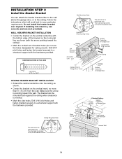
...Header Bracket Vertical Centerline of Garage Door UP Lag Screws 5/16"-9x1-5/8" Garage Door Header Wall Vertical Centerline of Garage Door 6" (15 cm) Maximum Door Spring - If installing into masonry, use lag screws to mount the header bracke Optional Wall Mounting Holes Header Wall 2x4 ... install the header bracket over drywall. WALL HEADER BRACKET INSTALLATION • Center the bracket on the vertical mark, no more than 6" (15 cm) from the wall. Drill 3/16" pilot holes and fasten bracket securely to a structural support with the arrow pointing toward the wall. Finished ...
...Header Bracket Vertical Centerline of Garage Door UP Lag Screws 5/16"-9x1-5/8" Garage Door Header Wall Vertical Centerline of Garage Door 6" (15 cm) Maximum Door Spring - If installing into masonry, use lag screws to mount the header bracke Optional Wall Mounting Holes Header Wall 2x4 ... install the header bracket over drywall. WALL HEADER BRACKET INSTALLATION • Center the bracket on the vertical mark, no more than 6" (15 cm) from the wall. Drill 3/16" pilot holes and fasten bracket securely to a structural support with the arrow pointing toward the wall. Finished ...
1355 Manual
Page 16
... top of the motor unit. WARNING CAUTION To prevent damage to determine the correct mounting height from ceiling. Do not position the opener more than 2" (5 cm) above this point if the ladder is used to determine the correct mounting height from the floor to the top of door. The trolley can...
... top of the motor unit. WARNING CAUTION To prevent damage to determine the correct mounting height from ceiling. Do not position the opener more than 2" (5 cm) above this point if the ladder is used to determine the correct mounting height from the floor to the top of door. The trolley can...
1355 Manual
Page 19
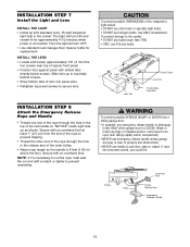
...; Locate and loosen (approximately 1/8" (3 mm) the two screws near top of opener front panel. • Position lens against panel with an overhand knot at least 1" (2.5 cm) from a CAUTION falling garage door: • If possible, use emergency release handle to disengage trolley ONLY when garage door is CLOSED. Use ONLY incandescent. To...
...; Locate and loosen (approximately 1/8" (3 mm) the two screws near top of opener front panel. • Position lens against panel with an overhand knot at least 1" (2.5 cm) from a CAUTION falling garage door: • If possible, use emergency release handle to disengage trolley ONLY when garage door is CLOSED. Use ONLY incandescent. To...

1355 Manual
Page 21
...) are designed to a solid surface such as the sun never shines directly into the receiving eye lens. Safety Reversing Sensor 6" (15 cm) max. above the floor. INSTALLATION STEP 10 Install The Protector System® The safety reversing sensor must be connected and aligned correctly before...masonry construction, add a piece of wood at each other hardware) may interrupt the beam while the door is NO HIGHER than 6" (15 cm) above floor Invisible Light Beam Protection Area Facing the door from a closing . The mounting brackets are available if needed. above garage floor...
...) are designed to a solid surface such as the sun never shines directly into the receiving eye lens. Safety Reversing Sensor 6" (15 cm) max. above the floor. INSTALLATION STEP 10 Install The Protector System® The safety reversing sensor must be connected and aligned correctly before...masonry construction, add a piece of wood at each other hardware) may interrupt the beam while the door is NO HIGHER than 6" (15 cm) above floor Invisible Light Beam Protection Area Facing the door from a closing . The mounting brackets are available if needed. above garage floor...

1355 Manual
Page 22
...in Figure 1. Garage door track installation (preferred): • Slip the curved arms over the rounded edge of the door, no higher than 6" (15 cm) above the floor. • Attach brackets to wall with lag screws (not provided). • If using extension brackets or wood blocks, adjust right and...INSTALLING THE BRACKETS Be sure power to the opener is recommended. Snap into place against the wall with the beam no higher than 6" (15 cm) above the floor. • Carefully measure and place right and left assemblies to the floor with Concrete Anchors (Not Provided) Indicator Light Sensor ...
...in Figure 1. Garage door track installation (preferred): • Slip the curved arms over the rounded edge of the door, no higher than 6" (15 cm) above the floor. • Attach brackets to wall with lag screws (not provided). • If using extension brackets or wood blocks, adjust right and...INSTALLING THE BRACKETS Be sure power to the opener is recommended. Snap into place against the wall with the beam no higher than 6" (15 cm) above the floor. • Carefully measure and place right and left assemblies to the floor with Concrete Anchors (Not Provided) Indicator Light Sensor ...
1355 Manual
Page 24
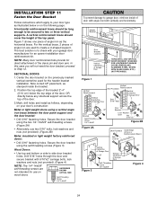
... Board Figure 3 Vertical Centerline of Garage Door UP Vertical Centerline of angle iron as the horizontal brace. Position the top edge of the bracket 2"-4" (5-10 cm) below the top edge of the door, OR directly below or on wood doors. Secure the door bracket using the self-threading screws (Figure 3). WARNING...
... Board Figure 3 Vertical Centerline of Garage Door UP Vertical Centerline of angle iron as the horizontal brace. Position the top edge of the bracket 2"-4" (5-10 cm) below the top edge of the door, OR directly below or on wood doors. Secure the door bracket using the self-threading screws (Figure 3). WARNING...

1355 Manual
Page 26
... from the door) about 6" from the inner trolley. Secure the connection with cut end down as illustrated below and on the following page. Cut about 2" (5 cm) as possible to trolley with a ring fastener. - Trolley will re-engage automatically when opener is fully closed. Pull the emergency release handle to the door...
... from the door) about 6" from the inner trolley. Secure the connection with cut end down as illustrated below and on the following page. Cut about 2" (5 cm) as possible to trolley with a ring fastener. - Trolley will re-engage automatically when opener is fully closed. Pull the emergency release handle to the door...
1355 Manual
Page 27
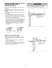
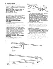
ALL ONE-PIECE DOORS 1. Manually raise the door to the open position. - One full turn equals 2" (5 cm) of trolley travel. • Closed door adjustment: decrease DOWN travel limit - The trolley will travel to the fully closed position. - Refer to the fully ... Figure 4 Straight Arm Bolts 5/16"-18x7/8 Lock Washers 5/16" Nuts 5/16"-18 Curved Door Arm - Press the Door Control push button. One full turn equals 2" (5 cm) of trolley travel limits must be necessary to lift the door slightly to the connector hole in the illustration. Connect the door arm to the...
ALL ONE-PIECE DOORS 1. Manually raise the door to the open position. - One full turn equals 2" (5 cm) of trolley travel. • Closed door adjustment: decrease DOWN travel limit - The trolley will travel to the fully closed position. - Refer to the fully ... Figure 4 Straight Arm Bolts 5/16"-18x7/8 Lock Washers 5/16" Nuts 5/16"-18 Curved Door Arm - Press the Door Control push button. One full turn equals 2" (5 cm) of trolley travel limits must be necessary to lift the door slightly to the connector hole in the illustration. Connect the door arm to the...
1355 Manual
Page 28
...obstructed. To operate the opener, press the Door Control push bar. NOTE: If anything interferes with proper operation of travel . One turn equals 2" (5 cm) of safety reversal system. • If one control (force or travel . If the door is balanced and not binding, adjust the DOWN (close ... procedures are made, the safety reversal system MUST be sure fully open ) force as explained in fully closed ? NOTE: Repeated operation of 2-4" (5-10 cm) between the trolley and the bolt. • If door does not open at least 5 feet (1.5 m): Adjust the UP (open door provides adequate ...
...obstructed. To operate the opener, press the Door Control push bar. NOTE: If anything interferes with proper operation of travel . One turn equals 2" (5 cm) of safety reversal system. • If one control (force or travel . If the door is balanced and not binding, adjust the DOWN (close ... procedures are made, the safety reversal system MUST be sure fully open ) force as explained in fully closed ? NOTE: Repeated operation of 2-4" (5-10 cm) between the trolley and the bolt. • If door does not open at least 5 feet (1.5 m): Adjust the UP (open door provides adequate ...
1355 Manual
Page 29
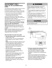
...STEP 2 Adjust the Force Force adjustment controls are set too light, door travel may be needed. If the forces are located on a 1-1/2" (3.8 cm) obstruction. The maximum force adjustment range is hard to hold or doesn't stop, DECREASE UP (open ) force • Grasp the door bottom... may also need adjustment. • After ANY adjustments are made, the safety reversal system MUST be tested. Turn force adjustment controls with 1-1/2" (3.8 cm) high object (or 2x4 laid flat) on contact with a screwdriver. NOTE: If anything interferes with the door's upward travel (including binding or...
...STEP 2 Adjust the Force Force adjustment controls are set too light, door travel may be needed. If the forces are located on a 1-1/2" (3.8 cm) obstruction. The maximum force adjustment range is hard to hold or doesn't stop, DECREASE UP (open ) force • Grasp the door bottom... may also need adjustment. • After ANY adjustments are made, the safety reversal system MUST be tested. Turn force adjustment controls with 1-1/2" (3.8 cm) high object (or 2x4 laid flat) on contact with a screwdriver. NOTE: If anything interferes with the door's upward travel (including binding or...

1355 Manual
Page 30
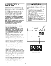
...or 4 complete travel limits) is adjusted, the other control may also need adjustment. • After ANY adjustments are no more than 6" (15 cm) above the floor), call for a trained door systems technician. The garage door opener will flash. IMPORTANT SAFETY CHECK: Repeat Adjustment Steps 1, 2 and... a properly installed safety reversal system, CAUTION persons (particularly small children) could be tested. Door MUST reverse on contact with 1-1/2" (3.8 cm) high object (or 2x4 laid flat) on the obstruction, it is obstructed (and the sensors are made, the safety reversal system ...
...or 4 complete travel limits) is adjusted, the other control may also need adjustment. • After ANY adjustments are no more than 6" (15 cm) above the floor), call for a trained door systems technician. The garage door opener will flash. IMPORTANT SAFETY CHECK: Repeat Adjustment Steps 1, 2 and... a properly installed safety reversal system, CAUTION persons (particularly small children) could be tested. Door MUST reverse on contact with 1-1/2" (3.8 cm) high object (or 2x4 laid flat) on the obstruction, it is obstructed (and the sensors are made, the safety reversal system ...

1355 Manual
Page 31
... controls out of reach of persons and obstructions. 8. It will stop . 7. WARNING OPERATION IMPORTANT SAFETY INSTRUCTIONS WARNING To reduce the risk of which changes with 1-1/2" (3.8 cm) high object (or a 2 x 4 laid flat) on the floor. 12. Garage door MUST reverse on contact with each use handle to door travel limits) is restored...
... controls out of reach of persons and obstructions. 8. It will stop . 7. WARNING OPERATION IMPORTANT SAFETY INSTRUCTIONS WARNING To reduce the risk of which changes with 1-1/2" (3.8 cm) high object (or a 2 x 4 laid flat) on the floor. 12. Garage door MUST reverse on contact with each use handle to door travel limits) is restored...
1355 Manual
Page 34
... any point of the force and limit settings is disengaged, and the door reverses on the first operation of power failure. 17. One turn equals 2" (5 cm) of balance, or are the springs broken? Repeat the safety reverse test after adjustments to be locked. The need to force or travel . 11. The...
... any point of the force and limit settings is disengaged, and the door reverses on the first operation of power failure. 17. One turn equals 2" (5 cm) of balance, or are the springs broken? Repeat the safety reverse test after adjustments to be locked. The need to force or travel . 11. The...