
Service Manual
Page 5
...3-10 Station ID 3-10 Faxtrace Mask 3-10 Homologation settings 3-11 Utilities 3-11 Fax NVRAM 3-11 Clr Phonebook 3-11 ERASE FFS 3-11 Repair information 4-1 Handling ESD-sensitive parts 4-1 Removal procedures 4-2 Covers 4-2 Extender cover removal 4-2 Front access cover removal 4-2 Left side cover removal... (autocompensator clutch 4-23 Input sensor #1 removal 4-24 Input sensor #2 (manual feed) removal 4-25 LVPS/HVPS card assembly removal 4-26 LVPS/HVPS to controller card cable removal 4-27 Manual feed clutch assembly removal 4-28 Network card removal 4-29 Operator panel assembly...
...3-10 Station ID 3-10 Faxtrace Mask 3-10 Homologation settings 3-11 Utilities 3-11 Fax NVRAM 3-11 Clr Phonebook 3-11 ERASE FFS 3-11 Repair information 4-1 Handling ESD-sensitive parts 4-1 Removal procedures 4-2 Covers 4-2 Extender cover removal 4-2 Front access cover removal 4-2 Left side cover removal... (autocompensator clutch 4-23 Input sensor #1 removal 4-24 Input sensor #2 (manual feed) removal 4-25 LVPS/HVPS card assembly removal 4-26 LVPS/HVPS to controller card cable removal 4-27 Manual feed clutch assembly removal 4-28 Network card removal 4-29 Operator panel assembly...
Service Manual
Page 14
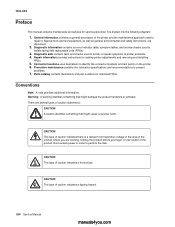
...manual contains maintenance procedures for making printer adjustments and removing and installing FRUs. 5. General information contains a general description of printer problems. 4. Diagnostic aids contains tests and checks used to locate or repeat symptoms of the printer and the maintenance approach used to repair it. Repair...caution indicates a hot surface. xiv Service Manual manuals4you.com Preventive maintenance contains the lubrication specifications and recommendations to identify the connector locations and test points on the printer. 6. CAUTION This type of caution ...
...manual contains maintenance procedures for making printer adjustments and removing and installing FRUs. 5. General information contains a general description of printer problems. 4. Diagnostic aids contains tests and checks used to locate or repeat symptoms of the printer and the maintenance approach used to repair it. Repair...caution indicates a hot surface. xiv Service Manual manuals4you.com Preventive maintenance contains the lubrication specifications and recommendations to identify the connector locations and test points on the printer. 6. CAUTION This type of caution ...

Service Manual
Page 15
... as needed to first print is 10 seconds. 7003-110 Lexmark X342n 27 ppm 25 ppm General information 1-1 Print speed Media Size 7003-100 Lexmark X340 7003-050 Lexmark X340n Letter-8.5 x 11 in this manual leads you to determine the symptom and repair the failure. See "Repair information" on media from tray 1 at 600 x 600 dpi. Note...
... as needed to first print is 10 seconds. 7003-110 Lexmark X342n 27 ppm 25 ppm General information 1-1 Print speed Media Size 7003-100 Lexmark X340 7003-050 Lexmark X340n Letter-8.5 x 11 in this manual leads you to determine the symptom and repair the failure. See "Repair information" on media from tray 1 at 600 x 600 dpi. Note...
Service Manual
Page 40
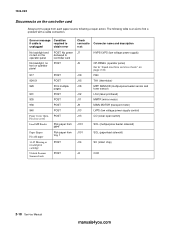
...) LVPS (low voltage power supply control) CO (cover open switch) SOL (multipurpose feeder solenoid) SOL (paperfeed solenoid) SC (smart chip) CCD 2-18 Service Manual manuals4you.com No power J7 delivered to controller card POST J5 917 924.01 929 931 935 936 940 Front Cover Open Pls close cover... service check" on operator panel POST. Error or message Condition if cable is an aid to find a problem with a cable connection. The following a repair action. 7003-XXX Disconnects on the controller card Always print a page from tray 1 POST POST J19 J15 J18 J12 J11 J9 J13 J13 J101 J101...
...) LVPS (low voltage power supply control) CO (cover open switch) SOL (multipurpose feeder solenoid) SOL (paperfeed solenoid) SC (smart chip) CCD 2-18 Service Manual manuals4you.com No power J7 delivered to controller card POST J5 917 924.01 929 931 935 936 940 Front Cover Open Pls close cover... service check" on operator panel POST. Error or message Condition if cable is an aid to find a problem with a cable connection. The following a repair action. 7003-XXX Disconnects on the controller card Always print a page from tray 1 POST POST J19 J15 J18 J12 J11 J9 J13 J13 J101 J101...

Service Manual
Page 97
...in the same orientation as the old. Remove the sensor and its back with the bottom of an advancing sheet. 7. 7003-XXX Input sensor #2 (manual feed) removal 1. Remove the screw (A) beside the left pick tire. The flag should be spring loaded against the leading edge of the MFP facing you.... Open the right side cover. Repair information 4-25 Remove the paper tray. 4. See "Upper right side cover removal" on the controller card (front, top of card). 3. Disconnect the sensor ...
...in the same orientation as the old. Remove the sensor and its back with the bottom of an advancing sheet. 7. 7003-XXX Input sensor #2 (manual feed) removal 1. Remove the screw (A) beside the left pick tire. The flag should be spring loaded against the leading edge of the MFP facing you.... Open the right side cover. Repair information 4-25 Remove the paper tray. 4. See "Upper right side cover removal" on the controller card (front, top of card). 3. Disconnect the sensor ...


