User's Guide
Page 35
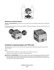
... duplex unit installed in the safety latches on both sides of the drawer until they click and stay recessed, and then lift the printer. If you are accessing the system board or installing optional hardware or memory devices sometime after setting up the... any cables going into the printer. Removing an optional drawer Warning-Potential Damage: Lifting the printer from the wall outlet before continuing. To remove an optional drawer, push in the printer. • T652n and T654n models do not support an optional duplex unit. Notes: • T652dn and T654dn models have any optional drawers....
... duplex unit installed in the safety latches on both sides of the drawer until they click and stay recessed, and then lift the printer. If you are accessing the system board or installing optional hardware or memory devices sometime after setting up the... any cables going into the printer. Removing an optional drawer Warning-Potential Damage: Lifting the printer from the wall outlet before continuing. To remove an optional drawer, push in the printer. • T652n and T654n models do not support an optional duplex unit. Notes: • T652dn and T654dn models have any optional drawers....

Service Manual
Page 1
Edition: September 17, 2009 Lexmark™ T650, T650n, T652dn, T654dn & T656dne Printer 4062-XXX • Table of contents • Start diagnostics • Safety and notices • Trademarks • Index Lexmark and Lexmark with diamond design are trademarks of Lexmark International, Inc., registered in the United States and/or other countries.
Edition: September 17, 2009 Lexmark™ T650, T650n, T652dn, T654dn & T656dne Printer 4062-XXX • Table of contents • Start diagnostics • Safety and notices • Trademarks • Index Lexmark and Lexmark with diamond design are trademarks of Lexmark International, Inc., registered in the United States and/or other countries.
Service Manual
Page 25
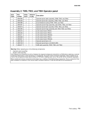
... aids to most computer networks. After you to verify the repair. General information 1-1 General information The Lexmark™ laser printers are available in the following models: Machine type 4062-01A 4062-21A 4062-23A 4062-41A 4062-43A...T654dn T656dne Configuration Network Network Network Network Network Network Maintenance approach The diagnostic information in this manual leads you complete the repair, perform tests as needed to the correct field replaceable unit (FRU) or part. See "Start" on page 2-1. The Lexmark laser printers are letter-quality page printers...
... aids to most computer networks. After you to verify the repair. General information 1-1 General information The Lexmark™ laser printers are available in the following models: Machine type 4062-01A 4062-21A 4062-23A 4062-41A 4062-43A...T654dn T656dne Configuration Network Network Network Network Network Network Maintenance approach The diagnostic information in this manual leads you complete the repair, perform tests as needed to the correct field replaceable unit (FRU) or part. See "Start" on page 2-1. The Lexmark laser printers are letter-quality page printers...
Service Manual
Page 529
...bezel (T650n) LCD screen bezel (T652n) LCD screen bezel (T652dn) LCD screen bezel (T654n) LCD screen bezel (T654dn) Operator panel bezel, left Operator panel bezel, left (NON USB) USB cable assembly (T650, T652, and T654) Warning: When replacing any of the components listed above without a POR after installing each one component at... Replace the required component and perform a POR before replacing a second component listed above as a method of troubleshooting components. If this procedure is not followed, the printer will be rendered inoperable. It must be used in another machine.
...bezel (T650n) LCD screen bezel (T652n) LCD screen bezel (T652dn) LCD screen bezel (T654n) LCD screen bezel (T654dn) Operator panel bezel, left Operator panel bezel, left (NON USB) USB cable assembly (T650, T652, and T654) Warning: When replacing any of the components listed above without a POR after installing each one component at... Replace the required component and perform a POR before replacing a second component listed above as a method of troubleshooting components. If this procedure is not followed, the printer will be rendered inoperable. It must be used in another machine.
Service Manual
Page 581
...7-31 Stapler/stacker controller card assembly 7-29 Sensor (bin full send 7-29 LCD screen bezel (T654dn 7-5 LCD screen bezel (T654n 7-5 Connection bezel assembly, rear (T652, T654, and T656 7-3 Connection bezel assembly, rear (T650 7-3 Operator panel door latch assembly (T656 ...flap 7-31 Media support (T654 7-3 Printer maintenance kit (100 V type 1 fuser 7-45 Printer maintenance kit (110 V type 1 fuser 7-45 Printer maintenance kit (220 V type 1 fuser 7-45 Printer maintenance kit (100 V type 2 fuser 7-45 Printer maintenance kit (110 V type 2 fuser 7-45 Printer maintenance kit (220 V ...
...7-31 Stapler/stacker controller card assembly 7-29 Sensor (bin full send 7-29 LCD screen bezel (T654dn 7-5 LCD screen bezel (T654n 7-5 Connection bezel assembly, rear (T652, T654, and T656 7-3 Connection bezel assembly, rear (T650 7-3 Operator panel door latch assembly (T656 ...flap 7-31 Media support (T654 7-3 Printer maintenance kit (100 V type 1 fuser 7-45 Printer maintenance kit (110 V type 1 fuser 7-45 Printer maintenance kit (220 V type 1 fuser 7-45 Printer maintenance kit (100 V type 2 fuser 7-45 Printer maintenance kit (110 V type 2 fuser 7-45 Printer maintenance kit (220 V ...


