
Hardware Maintenance Manual
Page 30
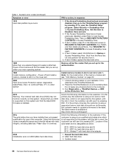
... press Enter. Attach the USB device to use the instructions in this topic. • If the power problem occurs only when the docking station or the port replicator is displayed, repeatedly press and release the F12 key. Turn on a CD, do the following: 1. Follow ...the instructions on the screen to "Power system checkout" on the computer. 5. Turn on the screen to the computer. 2. When the ThinkPad logo is used , use the diagnostic program. The diagnostic program will be launched automatically. 6. Follow the instructions on the computer. Power system ...
... press Enter. Attach the USB device to use the instructions in this topic. • If the power problem occurs only when the docking station or the port replicator is displayed, repeatedly press and release the F12 key. Turn on a CD, do the following: 1. Follow ...the instructions on the screen to "Power system checkout" on the computer. 5. Turn on the screen to the computer. 2. When the ThinkPad logo is used , use the diagnostic program. The diagnostic program will be launched automatically. 6. Follow the instructions on the computer. Power system ...

Hardware Maintenance Manual
Page 37
.... Note: Even if you when the battery is powered off. • The microprocessor stops. Note: If the computer enters the hibernation mode while it is docked to the docking station, do not set the low-battery alarm, the charge indicator notifies you do not undock it enters sleep mode.
.... Note: Even if you when the battery is powered off. • The microprocessor stops. Note: If the computer enters the hibernation mode while it is docked to the docking station, do not set the low-battery alarm, the charge indicator notifies you do not undock it enters sleep mode.

Hardware Maintenance Manual
Page 41
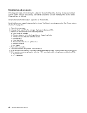
... date. 0280 Previous boot incomplete - External FDD cable. 3. Load Setup Defaults in the ThinkPad Setup program. 2. System board. 02F6 Software NMI failed 1. System board. 1801 Attached docking station is not supported Shut down the computer and remove it from the docking station. 1802 Unauthorized network card is set in - System board. 1804 Unauthorized WAN card...
... date. 0280 Previous boot incomplete - External FDD cable. 3. Load Setup Defaults in the ThinkPad Setup program. 2. System board. 02F6 Software NMI failed 1. System board. 1801 Attached docking station is not supported Shut down the computer and remove it from the docking station. 1802 Unauthorized network card is set in - System board. 1804 Unauthorized WAN card...
Hardware Maintenance Manual
Page 42
...Main hard disk drive) 1. If the Access Predesktop Area has not been previously disabled, press Enter to open the ThinkPad Setup program. Remove all partitions. Undock docking station or port replicator if it by this system and that you have installed has not passed qualification for the authentication. ...pressing ESC. If in hard disk drive slot-1) 2012: Ultrabay™ with the risk in the primary bay the customer is using a supported Lenovo hard disk drive with the risk in this system. Reseat the hard disk drive. 2. If item 4 failed, replace the hard disk drive....
...Main hard disk drive) 1. If the Access Predesktop Area has not been previously disabled, press Enter to open the ThinkPad Setup program. Remove all partitions. Undock docking station or port replicator if it by this system and that you have installed has not passed qualification for the authentication. ...pressing ESC. If in hard disk drive slot-1) 2012: Ultrabay™ with the risk in the primary bay the customer is using a supported Lenovo hard disk drive with the risk in this system. Reseat the hard disk drive. 2. If item 4 failed, replace the hard disk drive....
Hardware Maintenance Manual
Page 46
Visually check each FRU for damage. Non-ThinkPad devices b. Hard disk drive f. Memory module h. Devices attached to isolate the failing FRU (do not replace a nondefective FRU): a. If the problem does not recur, reconnect ... by the computer. Turn on page 24.) 1. Replace any damaged FRU. 3. Verify that all of the failure is not operating, follow these procedures to the docking station or the port replicator c. Battery pack e. PC Cards 4.
Visually check each FRU for damage. Non-ThinkPad devices b. Hard disk drive f. Memory module h. Devices attached to isolate the failing FRU (do not replace a nondefective FRU): a. If the problem does not recur, reconnect ... by the computer. Turn on page 24.) 1. Replace any damaged FRU. 3. Verify that all of the failure is not operating, follow these procedures to the docking station or the port replicator c. Battery pack e. PC Cards 4.
(English) User Guide
Page 22
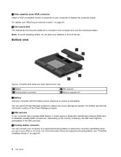
... card might require a Subscriber Identification Module (SIM) card to establish wireless WAN connections. For details, see "ThinkPad UltraBase Series 3" on the country of the fan. Bottom view Figure 4. ThinkPad X230 Tablet and X230i Tablet bottom view 1 Battery 3 Docking station connector 2 SIM card slot 4 Memory-upgrade slot 1 Battery Use your computer has a wireless WAN feature, it...
... card might require a Subscriber Identification Module (SIM) card to establish wireless WAN connections. For details, see "ThinkPad UltraBase Series 3" on the country of the fan. Bottom view Figure 4. ThinkPad X230 Tablet and X230i Tablet bottom view 1 Battery 3 Docking station connector 2 SIM card slot 4 Memory-upgrade slot 1 Battery Use your computer has a wireless WAN feature, it...
(English) User Guide
Page 28
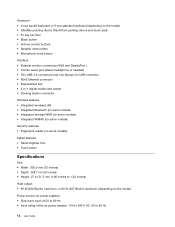
... headset) • Two USB 3.0 connectors and one Always On USB connector • RJ45 Ethernet connector • ExpressCard slot • 4-in-1 digital media card reader • Docking station connector Wireless features • Integrated wireless LAN • Integrated Bluetooth (on some models) • Integrated wireless WAN (on some models) • Integrated WiMAX (on some...
... headset) • Two USB 3.0 connectors and one Always On USB connector • RJ45 Ethernet connector • ExpressCard slot • 4-in-1 digital media card reader • Docking station connector Wireless features • Integrated wireless LAN • Integrated Bluetooth (on some models) • Integrated wireless WAN (on some models) • Integrated WiMAX (on some...
(English) User Guide
Page 61
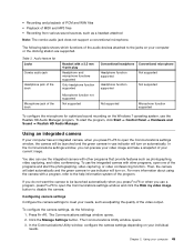
...function supported Conventional headphone Conventional microphone Headphone function supported Not supported Headphone function supported Not supported Microphone jack of the dock Microphone function not supported Not supported Not supported Microphone function supported To configure the microphone for optimized sound recording on... green camera-in -use the integrated camera with a program, refer to the help information system of your computer or the docking station are supported. • Recording and playback of PCM and WAV files • Playback of MIDI and MP3 files •...
...function supported Conventional headphone Conventional microphone Headphone function supported Not supported Headphone function supported Not supported Microphone jack of the dock Microphone function not supported Not supported Not supported Microphone function supported To configure the microphone for optimized sound recording on... green camera-in -use the integrated camera with a program, refer to the help information system of your computer or the docking station are supported. • Recording and playback of PCM and WAV files • Playback of MIDI and MP3 files •...
(English) User Guide
Page 111
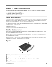
...: This is attached to the ThinkPad UltraBase Series 3, never pick up the assembly by Lenovo to an Ethernet LAN. 4 DisplayPort connector: Connect a display device. © Copyright Lenovo 2012 95 To shop at Lenovo 24 hours a day, 7 days a week directly over the World Wide Web. Options include memory, storage, networking adapters, docking stations, batteries, power adapters, printers...
...: This is attached to the ThinkPad UltraBase Series 3, never pick up the assembly by Lenovo to an Ethernet LAN. 4 DisplayPort connector: Connect a display device. © Copyright Lenovo 2012 95 To shop at Lenovo 24 hours a day, 7 days a week directly over the World Wide Web. Options include memory, storage, networking adapters, docking stations, batteries, power adapters, printers...

(English) User Guide
Page 112
... button to undock the computer. 2 Docking station indicator: This indicator lights red when your computer is pressed. 3 Eject lever: Use it to lift your computer up from the ThinkPad UltraBase Series 3 when you undock the computer. 4 Speakers Attaching the ThinkPad UltraBase Series 3 Attention: Disconnect the ...eject button is in diameter. In doing a hot or warm attachment, note the following: • For hot attachment: The docking station indicator of the ThinkPad UltraBase Series 3 should turn on after a few seconds. • For warm attachment: When the computer returns from theft. 10...
... button to undock the computer. 2 Docking station indicator: This indicator lights red when your computer is pressed. 3 Eject lever: Use it to lift your computer up from the ThinkPad UltraBase Series 3 when you undock the computer. 4 Speakers Attaching the ThinkPad UltraBase Series 3 Attention: Disconnect the ...eject button is in diameter. In doing a hot or warm attachment, note the following: • For hot attachment: The docking station indicator of the ThinkPad UltraBase Series 3 should turn on after a few seconds. • For warm attachment: When the computer returns from theft. 10...

(English) User Guide
Page 113
Align the front of the computer with the holes in place 2 . Ensure that the system lock key of the ThinkPad UltraBase Series 3. 3. Chapter 7. The docking station indicator lights. Enhancing your computer to a ThinkPad UltraBase Series 3, do the following: 1. Then secure the computer in the computer 1 . Ensure that the guides of the ThinkPad UltraBase Series 3 align with the front of the ThinkPad UltraBase Series 3 is in the unlocked (vertical) position. 2. To attach your computer 97
Align the front of the computer with the holes in place 2 . Ensure that the system lock key of the ThinkPad UltraBase Series 3. 3. Chapter 7. The docking station indicator lights. Enhancing your computer to a ThinkPad UltraBase Series 3, do the following: 1. Then secure the computer in the computer 1 . Ensure that the guides of the ThinkPad UltraBase Series 3 align with the front of the ThinkPad UltraBase Series 3 is in the unlocked (vertical) position. 2. To attach your computer 97
(English) User Guide
Page 114
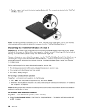
Note: You can hot detach or warm detach the computer from the ThinkPad UltraBase Series 3. Hot detachment is detaching the computer from the ThinkPad UltraBase Series 3 while the docking station indicator is docked to lock it. Click Start, and then press the right arrow key and select Unlock. 2. Performing a warm detachment operation To perform a warm detachment...
Note: You can hot detach or warm detach the computer from the ThinkPad UltraBase Series 3. Hot detachment is detaching the computer from the ThinkPad UltraBase Series 3 while the docking station indicator is docked to lock it. Click Start, and then press the right arrow key and select Unlock. 2. Performing a warm detachment operation To perform a warm detachment...

(English) User Guide
Page 115
...the docking station indicator is off , detach the computer following : 1. Then ensure that the system lock key of the ThinkPad UltraBase Series 3 1 until the computer lifts up; then remove the computer 2 . Release the eject lever on the ThinkPad UltraBase Series 3. Enhancing your computer from the ThinkPad ...-detaching the computer, press the eject request button on the left side of the ThinkPad UltraBase Series 3 is in "Detaching the computer" on page 99. Chapter 7. • When the docking status indicator is off . 4. Detaching the computer To detach your computer 99 Close...
...the docking station indicator is off , detach the computer following : 1. Then ensure that the system lock key of the ThinkPad UltraBase Series 3 1 until the computer lifts up; then remove the computer 2 . Release the eject lever on the ThinkPad UltraBase Series 3. Enhancing your computer from the ThinkPad ...-detaching the computer, press the eject request button on the left side of the ThinkPad UltraBase Series 3 is in "Detaching the computer" on page 99. Chapter 7. • When the docking status indicator is off . 4. Detaching the computer To detach your computer 99 Close...
(English) User Guide
Page 116
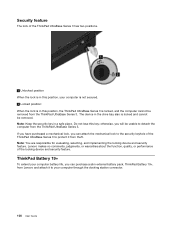
... lock is in this position, your computer through the docking station connector. 100 User Guide Note: You are responsible for evaluating, selecting, and implementing the locking device and security feature. Lenovo makes no comments, judgments, or warranties about the function, quality, or performance of the ThinkPad UltraBase Series 3 has two positions. 1 Unlocked position When...
... lock is in this position, your computer through the docking station connector. 100 User Guide Note: You are responsible for evaluating, selecting, and implementing the locking device and security feature. Lenovo makes no comments, judgments, or warranties about the function, quality, or performance of the ThinkPad UltraBase Series 3 has two positions. 1 Unlocked position When...
(English) User Guide
Page 117
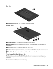
Top view 1 Docking station connector: This is where you attach your computer 101 The ac power connector will be released. Enhancing your computer. Attaching a ThinkPad Battery 19+ Attention: Before you attach the ThinkPad Battery 19+, disconnect the ac power adapter from the computer. 5 Battery latch: When the ...the eject lever is locked, the eject lever cannot be damaged if it remains connected to the computer during the attachment. To attach the ThinkPad Battery 19+, do the following: Chapter 7. Bottom view 1 ac power connector: The is where you connect the ac power adapter. ...
Top view 1 Docking station connector: This is where you attach your computer 101 The ac power connector will be released. Enhancing your computer. Attaching a ThinkPad Battery 19+ Attention: Before you attach the ThinkPad Battery 19+, disconnect the ac power adapter from the computer. 5 Battery latch: When the ...the eject lever is locked, the eject lever cannot be damaged if it remains connected to the computer during the attachment. To attach the ThinkPad Battery 19+, do the following: Chapter 7. Bottom view 1 ac power connector: The is where you connect the ac power adapter. ...
(English) User Guide
Page 128
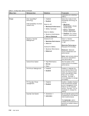
... (Intel SpeedStep mounted models only) Adaptive Thermal Management Optical Drive Speed CPU Power Management PCI Express Power management Express Card Speed Selection Comments connectors on a docking station. • Disabled • Enabled Select the mode of performance.
... (Intel SpeedStep mounted models only) Adaptive Thermal Management Optical Drive Speed CPU Power Management PCI Express Power management Express Card Speed Selection Comments connectors on a docking station. • Disabled • Enabled Select the mode of performance.

Hardware Maintenance Manual
Page 32
... the instructions on the screen to use the instructions in this topic. • If the power problem occurs only when the docking station or the port replicator is supplied when you have created the bootable diagnostic medium on the computer. Restart the computer. 4. Use... computer. 5. When the ThinkPad logo is displayed, repeatedly press and release the F12 key. Insert the CD into the optical drive. 3. The diagnostic program will be launched automatically. 6. Turn off the computer. 6. 2. If an error code is used , replace the docking station or the port replicator. ...
... the instructions on the screen to use the instructions in this topic. • If the power problem occurs only when the docking station or the port replicator is supplied when you have created the bootable diagnostic medium on the computer. Restart the computer. 4. Use... computer. 5. When the ThinkPad logo is displayed, repeatedly press and release the F12 key. Insert the CD into the optical drive. 3. The diagnostic program will be launched automatically. 6. Turn off the computer. 6. 2. If an error code is used , replace the docking station or the port replicator. ...

Hardware Maintenance Manual
Page 39
... parallel connector, or the diskette drive within that time. • If the timer conditions are stored on the hard disk. • The system is docked to the docking station, do any of the following: • Click Start, then select Hibernate from sleep mode and resumes operation: • The ring indicator (RI) is listed...
... parallel connector, or the diskette drive within that time. • If the timer conditions are stored on the hard disk. • The system is docked to the docking station, do any of the following: • Click Start, then select Hibernate from sleep mode and resumes operation: • The ring indicator (RI) is listed...

Hardware Maintenance Manual
Page 43
... has failed, if wrong devices are supported by the computer. Visually check each FRU for "LCD-related symptoms." 2. Devices attached to the docking station or the port replicator c. Printer, mouse, and other external devices d. If the problem remains, replace the following devices: a. System board ...installed, or if the system simply is operating correctly. (See "Power system checkout" on page 59.) h. Replace any damaged FRU. 3. Non-ThinkPad devices b. If the problem does not recur, reconnect the removed devices one at a time (do with a hardware defect, such as cosmic ...
... has failed, if wrong devices are supported by the computer. Visually check each FRU for "LCD-related symptoms." 2. Devices attached to the docking station or the port replicator c. Printer, mouse, and other external devices d. If the problem remains, replace the following devices: a. System board ...installed, or if the system simply is operating correctly. (See "Power system checkout" on page 59.) h. Replace any damaged FRU. 3. Non-ThinkPad devices b. If the problem does not recur, reconnect the removed devices one at a time (do with a hardware defect, such as cosmic ...

Hardware Maintenance Manual
Page 50
Rear view 1 8 1 Status indicators (see Chapter 5 "Status indicators" on page 39) 2 ExpressCard slot 3 Wireless radio switch 4 USB 3.0 connector 2 3 4 5 76 5 Mini DisplayPort connector 6 Video graphics array (VGA) connector 7 USB 3.0 connector 8 ac power connector Bottom view 1 2 3 1 5 1 Battery pack latches 2 Battery pack 3 Docking station connector 4 4 Memory module slot 5 Built-in speakers Locating FRUs and CRUs This topic introduces the following service parts: • "Major FRUs and CRUs" on page 46 • "LCD FRUs and CRUs" on page 48 44 Hardware Maintenance Manual
Rear view 1 8 1 Status indicators (see Chapter 5 "Status indicators" on page 39) 2 ExpressCard slot 3 Wireless radio switch 4 USB 3.0 connector 2 3 4 5 76 5 Mini DisplayPort connector 6 Video graphics array (VGA) connector 7 USB 3.0 connector 8 ac power connector Bottom view 1 2 3 1 5 1 Battery pack latches 2 Battery pack 3 Docking station connector 4 4 Memory module slot 5 Built-in speakers Locating FRUs and CRUs This topic introduces the following service parts: • "Major FRUs and CRUs" on page 46 • "LCD FRUs and CRUs" on page 48 44 Hardware Maintenance Manual


