
(English) Service and Troubleshooting Guide
Page 33
... access panel is removed, the CRU is typically secured by more than two screws. Self-service CRUs are responsible for several critical CRUs. © Copyright Lenovo 2009 19 To start the Access Help program, do as memory, wireless cards, notebook keyboards, and palm rests...computer parts that are listed in the table on the following page. Online Access Help and Lenovo Internet Support site, http:// www.lenovo.com/CRUs, provide instructions for the customer to remove a maximum of two screws, whereas optional-service CRUs require some products, such components as ...
... access panel is removed, the CRU is typically secured by more than two screws. Self-service CRUs are responsible for several critical CRUs. © Copyright Lenovo 2009 19 To start the Access Help program, do as memory, wireless cards, notebook keyboards, and palm rests...computer parts that are listed in the table on the following page. Online Access Help and Lenovo Internet Support site, http:// www.lenovo.com/CRUs, provide instructions for the customer to remove a maximum of two screws, whereas optional-service CRUs require some products, such components as ...

Hardware Maintenance Manual
Page 3
...number of the system unit 66 Retaining the UUID 67 Reading or writing the ECA information . . . 67 Chapter 9. Removing and replacing a FRU 69 Before servicing ThinkPad T510, T510i, and W510 70 1010 Battery pack 70 1020 Serial Ultrabay Enhanced device or travel bezel 71 1030 DIMM slot ... drive and storage converter 74 1060 Keyboard 76 i Related service information 41 Restoring the factory contents by using Recovery Disc Set 41 Passwords 42 Power-on password 42 Hard-disk password 42 Supervisor password 43 © Copyright Lenovo 2009, 2012 How to remove the power-on password . . ...
...number of the system unit 66 Retaining the UUID 67 Reading or writing the ECA information . . . 67 Chapter 9. Removing and replacing a FRU 69 Before servicing ThinkPad T510, T510i, and W510 70 1010 Battery pack 70 1020 Serial Ultrabay Enhanced device or travel bezel 71 1030 DIMM slot ... drive and storage converter 74 1060 Keyboard 76 i Related service information 41 Restoring the factory contents by using Recovery Disc Set 41 Passwords 42 Power-on password 42 Hard-disk password 42 Supervisor password 43 © Copyright Lenovo 2009, 2012 How to remove the power-on password . . ...

Hardware Maintenance Manual
Page 40
... "Run Diagnostics" on the computer. 3. Diagnostics ➙ Video Adapter 2. Keyboard 1. Remove any physical shock to the computer while the test is displayed at the lower left of ThinkPad Notebook, the Rescue and Recovery® workspace enables you to run the test again. 34 ThinkPad T510, T510i, and W510 Hardware Maintenance Manual Interactive Tests ➙ Diskette...
... "Run Diagnostics" on the computer. 3. Diagnostics ➙ Video Adapter 2. Keyboard 1. Remove any physical shock to the computer while the test is displayed at the lower left of ThinkPad Notebook, the Rescue and Recovery® workspace enables you to run the test again. 34 ThinkPad T510, T510i, and W510 Hardware Maintenance Manual Interactive Tests ➙ Diskette...
Hardware Maintenance Manual
Page 50
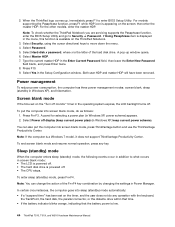
..., press Fn+F4. Select Password. 5. Both user HDP and master HDP will have been removed. To put the computer into screen blank mode, press ThinkVantage button and use the ThinkVantage Productivity... screen; Select Hard-disk x password, where x is low. 44 ThinkPad T510, T510i, and W510 Hardware Maintenance Manual Press F10. 9. When the ThinkPad logo comes up window opens. 6. Press Fn+F3. You can change.... To end screen blank mode and resume normal operation, press any operation with the keyboard, the TrackPoint, the hard disk, the parallel connector, or the diskette drive within ...
..., press Fn+F4. Select Password. 5. Both user HDP and master HDP will have been removed. To put the computer into screen blank mode, press ThinkVantage button and use the ThinkVantage Productivity... screen; Select Hard-disk x password, where x is low. 44 ThinkPad T510, T510i, and W510 Hardware Maintenance Manual Press F10. 9. When the ThinkPad logo comes up window opens. 6. Press Fn+F3. You can change.... To end screen blank mode and resume normal operation, press any operation with the keyboard, the TrackPoint, the hard disk, the parallel connector, or the diskette drive within ...

Hardware Maintenance Manual
Page 53
...2. Chapter 4. System board. 0196 Security hardware removed 1. The remote configuration for the security chip has failed. Remove either a Mini-PCI Card or a modem daughter card. or press Esc to clear this error. 2. System board. 021x Keyboard error. Embedded Security hardware tamper detected. Enter ... Utility by pressing F10. 2. System board. 01C8 Two or more Ethernet devices are found . Remove all but one of them . 1. Remove all but one of the keyboard and the auxiliary input device. 0220 Load Setup Defaults in BIOS Setup Utility. 3. System board....
...2. Chapter 4. System board. 0196 Security hardware removed 1. The remote configuration for the security chip has failed. Remove either a Mini-PCI Card or a modem daughter card. or press Esc to clear this error. 2. System board. 021x Keyboard error. Embedded Security hardware tamper detected. Enter ... Utility by pressing F10. 2. System board. 01C8 Two or more Ethernet devices are found . Remove all but one of them . 1. Remove all but one of the keyboard and the auxiliary input device. 0220 Load Setup Defaults in BIOS Setup Utility. 3. System board....
Hardware Maintenance Manual
Page 82
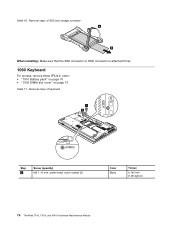
Table 16. Removal steps of SSD and storage converter 4 5 When installing: Make sure that the SSD connector or HDD connector is attached firmly. 1060 Keyboard For access, remove these FRUs in order: • "1010 Battery pack" on page 70 • "1030 DIMM slot cover" on page 73 Table 17. Removal steps of keyboard 1 1 Step 1 Screw (quantity) M2 × 14 mm, wafer-head, nylon-coated (2) Color Black Torque 0.181 Nm (1.85 kgfcm) 76 ThinkPad T510, T510i, and W510 Hardware Maintenance Manual
Table 16. Removal steps of SSD and storage converter 4 5 When installing: Make sure that the SSD connector or HDD connector is attached firmly. 1060 Keyboard For access, remove these FRUs in order: • "1010 Battery pack" on page 70 • "1030 DIMM slot cover" on page 73 Table 17. Removal steps of keyboard 1 1 Step 1 Screw (quantity) M2 × 14 mm, wafer-head, nylon-coated (2) Color Black Torque 0.181 Nm (1.85 kgfcm) 76 ThinkPad T510, T510i, and W510 Hardware Maintenance Manual

Hardware Maintenance Manual
Page 83
Removing and replacing a FRU 77 Removal steps of keyboard (continued) Push down the keyboard a little toward the arrow 2 until the front edge of the keyboard is detached from the keyboard bezel. 2 Lift the keyboard a little in the direction shown by arrow 3 , and then detach the connector 4 . 3 4 When installing the keyboard, do as follows: Chapter 9. Table 17.
Removing and replacing a FRU 77 Removal steps of keyboard (continued) Push down the keyboard a little toward the arrow 2 until the front edge of the keyboard is detached from the keyboard bezel. 2 Lift the keyboard a little in the direction shown by arrow 3 , and then detach the connector 4 . 3 4 When installing the keyboard, do as follows: Chapter 9. Table 17.

Hardware Maintenance Manual
Page 85
Make sure that the front side of keyboard (continued) 3. b b b 5. Gently press the keys with your thumbs and try to slide the keyboard toward you. 4. Installation steps of the keyboard ( b ) is housed firmly. Removing and replacing a FRU 79 Table 18. Secure the keyboard by tightening the screws from the bottom side of the computer. 1070 DIMM (upper slot) For access, remove these FRUs in order: • "1010 Battery pack" on page 70 • "1030 DIMM slot cover" on page 73 • "1060 Keyboard" on page 76 Chapter 9.
Make sure that the front side of keyboard (continued) 3. b b b 5. Gently press the keys with your thumbs and try to slide the keyboard toward you. 4. Installation steps of the keyboard ( b ) is housed firmly. Removing and replacing a FRU 79 Table 18. Secure the keyboard by tightening the screws from the bottom side of the computer. 1070 DIMM (upper slot) For access, remove these FRUs in order: • "1010 Battery pack" on page 70 • "1030 DIMM slot cover" on page 73 • "1060 Keyboard" on page 76 Chapter 9.

Hardware Maintenance Manual
Page 86
... page 76 80 ThinkPad T510, T510i, and W510 Hardware Maintenance Manual a b When installing: Insert the notched end of DIMM (upper slot) 1 2 1 Note: If only one DIMM is firmly fixed in the slot and does not move easily. 1080 PCI Express Mini Card for wireless LAN For access, remove these FRUs in ... Battery pack" on page 70 • "1030 DIMM slot cover" on page 73 • "1060 Keyboard" on the computer you are servicing, the card must be installed in SLOT-0 ( a ), but not in SLOT-1 ( b ). Removal steps of the DIMM into the place. Table 19. Make sure that it snaps into the socket.
... page 76 80 ThinkPad T510, T510i, and W510 Hardware Maintenance Manual a b When installing: Insert the notched end of DIMM (upper slot) 1 2 1 Note: If only one DIMM is firmly fixed in the slot and does not move easily. 1080 PCI Express Mini Card for wireless LAN For access, remove these FRUs in ... Battery pack" on page 70 • "1030 DIMM slot cover" on page 73 • "1060 Keyboard" on the computer you are servicing, the card must be installed in SLOT-0 ( a ), but not in SLOT-1 ( b ). Removal steps of the DIMM into the place. Table 19. Make sure that it snaps into the socket.
Hardware Maintenance Manual
Page 88
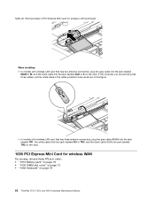
... PCI Express Mini Card for wireless WAN For access, remove these FRUs in this figure. • In models with wireless LAN card that has three antenna connectors, plug the gray cable (MAIN) into the jack ... connectors, plug the gray cable into the jack labeled MAIN or M, and the black cable into the jack labeled AUX or A on page 76 82 ThinkPad T510, T510i, and W510 Hardware Maintenance Manual If the computer you are servicing has three cables, put the white cable in the cable protection tube as...
... PCI Express Mini Card for wireless WAN For access, remove these FRUs in this figure. • In models with wireless LAN card that has three antenna connectors, plug the gray cable (MAIN) into the jack ... connectors, plug the gray cable into the jack labeled MAIN or M, and the black cable into the jack labeled AUX or A on page 76 82 ThinkPad T510, T510i, and W510 Hardware Maintenance Manual If the computer you are servicing has three cables, put the white cable in the cable protection tube as...
Hardware Maintenance Manual
Page 90
... • "1030 DIMM slot cover" on page 73 • "1060 Keyboard" on page 76 Attention: Before removing the keyboard bezel assembly, make sure that you press the ExpressCard blank bezel or ExpressCard 1 , it pops out 2 . 84 ThinkPad T510, T510i, and W510 Hardware Maintenance Manual Removal steps of PCI Express Mini Card for wireless WAN (continued) 4 When...
... • "1030 DIMM slot cover" on page 73 • "1060 Keyboard" on page 76 Attention: Before removing the keyboard bezel assembly, make sure that you press the ExpressCard blank bezel or ExpressCard 1 , it pops out 2 . 84 ThinkPad T510, T510i, and W510 Hardware Maintenance Manual Removal steps of PCI Express Mini Card for wireless WAN (continued) 4 When...

Hardware Maintenance Manual
Page 91
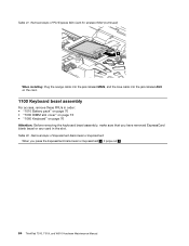
Table 22. Removal steps of ExpressCard blank bezel or ExpressCard (continued) 1 2 When installing: Make sure that the bezel or the card is attached to the keyboard bezel. Chapter 9. Table 23. Removing and replacing a FRU 85 Removal steps of keyboard bezel assembly Note: The speaker assembly is correctly oriented as shown in this figure.
Table 22. Removal steps of ExpressCard blank bezel or ExpressCard (continued) 1 2 When installing: Make sure that the bezel or the card is attached to the keyboard bezel. Chapter 9. Table 23. Removing and replacing a FRU 85 Removal steps of keyboard bezel assembly Note: The speaker assembly is correctly oriented as shown in this figure.
Hardware Maintenance Manual
Page 92
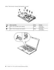
Table 23. Removal steps of keyboard bezel assembly (continued) 2 2 2 1 1 1 2 12 Step 1 2 Screw (quantity) M2 × 4 mm, bind-head, nylon-coated (4) M2 × 14 mm, bind-head, nylon-coated (7) 3 4 Color Black Black Torque 0.181 Nm (1.85 kgfcm) 0.181 Nm (1.85 kgfcm) 86 ThinkPad T510, T510i, and W510 Hardware Maintenance Manual
Table 23. Removal steps of keyboard bezel assembly (continued) 2 2 2 1 1 1 2 12 Step 1 2 Screw (quantity) M2 × 4 mm, bind-head, nylon-coated (4) M2 × 14 mm, bind-head, nylon-coated (7) 3 4 Color Black Black Torque 0.181 Nm (1.85 kgfcm) 0.181 Nm (1.85 kgfcm) 86 ThinkPad T510, T510i, and W510 Hardware Maintenance Manual

Hardware Maintenance Manual
Page 93
Removing and replacing a FRU 87 Table 23. Removal steps of keyboard bezel assembly (continued) 6 7 5 5 6 1110 Bluetooth daughter card (BDC-2.1) For access, remove these FRUs in order: • "1010 Battery pack" on page 70 • "1060 Keyboard" on page 76 • "1100 Keyboard bezel assembly" on page 84 Chapter 9.
Removing and replacing a FRU 87 Table 23. Removal steps of keyboard bezel assembly (continued) 6 7 5 5 6 1110 Bluetooth daughter card (BDC-2.1) For access, remove these FRUs in order: • "1010 Battery pack" on page 70 • "1060 Keyboard" on page 76 • "1100 Keyboard bezel assembly" on page 84 Chapter 9.

Hardware Maintenance Manual
Page 94
...88 ThinkPad T510, T510i, and W510 Hardware Maintenance Manual Color Silver Torque 0.181 Nm (1.85 kgfcm) 1120 Backup battery For access, remove these FRUs in order: • "1010 Battery pack" on page 70 • "1030 DIMM slot cover" on page 73 • "1060 Keyboard" on page 76 • "1100 Keyboard bezel... assembly" on page 84 DANGER Use only the battery specified in the parts list for your computer. Removal steps of BDC-2.1 1 2 Step 1 Screw (quantity) M2 × 3 mm, ...
...88 ThinkPad T510, T510i, and W510 Hardware Maintenance Manual Color Silver Torque 0.181 Nm (1.85 kgfcm) 1120 Backup battery For access, remove these FRUs in order: • "1010 Battery pack" on page 70 • "1030 DIMM slot cover" on page 73 • "1060 Keyboard" on page 76 • "1100 Keyboard bezel... assembly" on page 84 DANGER Use only the battery specified in the parts list for your computer. Removal steps of BDC-2.1 1 2 Step 1 Screw (quantity) M2 × 3 mm, ...

Hardware Maintenance Manual
Page 95
Table 25. Removing and replacing a FRU 89 Removal steps of backup battery 2 1 When installing: Make sure that the battery connector is attached firmly. 1130 Smart Card or Contactless Smart Card or Smart Card dummy spacer For access, remove these FRUs in order: • "1010 Battery pack" on page 70 • "1030 DIMM slot cover" on page 73 • "1060 Keyboard" on page 76 • "1100 Keyboard bezel assembly" on page 84 Chapter 9.
Table 25. Removing and replacing a FRU 89 Removal steps of backup battery 2 1 When installing: Make sure that the battery connector is attached firmly. 1130 Smart Card or Contactless Smart Card or Smart Card dummy spacer For access, remove these FRUs in order: • "1010 Battery pack" on page 70 • "1030 DIMM slot cover" on page 73 • "1060 Keyboard" on page 76 • "1100 Keyboard bezel assembly" on page 84 Chapter 9.

Hardware Maintenance Manual
Page 98
Removal steps of dummy card and spacer 3 1 1 2 Step 1 Screw (quantity) M2 × 3 mm, wafer-head, nylon-coated (4) 1140 Speaker assembly For access, remove these FRUs in order: • "1010 Battery pack" on page 70 • "1030 DIMM slot cover" on page 73 • "1060 Keyboard" on page 76 • "1100 Keyboard bezel assembly" on page 84 Color Silver Torque 0.181 Nm (1.85 kgfcm) 92 ThinkPad T510, T510i, and W510 Hardware Maintenance Manual Table 28.
Removal steps of dummy card and spacer 3 1 1 2 Step 1 Screw (quantity) M2 × 3 mm, wafer-head, nylon-coated (4) 1140 Speaker assembly For access, remove these FRUs in order: • "1010 Battery pack" on page 70 • "1030 DIMM slot cover" on page 73 • "1060 Keyboard" on page 76 • "1100 Keyboard bezel assembly" on page 84 Color Silver Torque 0.181 Nm (1.85 kgfcm) 92 ThinkPad T510, T510i, and W510 Hardware Maintenance Manual Table 28.
Hardware Maintenance Manual
Page 100
...not remove them. For those models, skip the step 5 . 3 5 5 4a 4c 4d 4b 94 ThinkPad T510, T510i, and W510 Hardware Maintenance Manual Note: Loosen the screws 4a to 4d in order: • "1010 Battery pack" on page 70 • "1030 DIMM slot cover" on page 73 • "1060 Keyboard" on... page 76 • "1100 Keyboard bezel assembly" on page 84 • ...
...not remove them. For those models, skip the step 5 . 3 5 5 4a 4c 4d 4b 94 ThinkPad T510, T510i, and W510 Hardware Maintenance Manual Note: Loosen the screws 4a to 4d in order: • "1010 Battery pack" on page 70 • "1030 DIMM slot cover" on page 73 • "1060 Keyboard" on... page 76 • "1100 Keyboard bezel assembly" on page 84 • ...
Hardware Maintenance Manual
Page 102
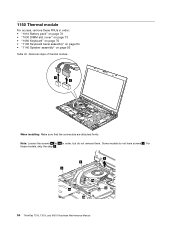
Removal steps of rough handling. 96 ThinkPad T510, T510i, and W510 Hardware Maintenance Manual Table 30. When you service the CPU, avoid any kind of thermal module (continued) a For Workstation models: a a 1160 CPU For access, remove these FRUs in order: • "1010 Battery pack" on page 70 • "1030 DIMM slot cover" on page 73 • "1060 Keyboard" on page 76 • "1100 Keyboard bezel assembly" on page 84 • "1140 Speaker assembly" on page 92 • "1150 Thermal module" on page 94 Attention: CPU is extremely sensitive.
Removal steps of rough handling. 96 ThinkPad T510, T510i, and W510 Hardware Maintenance Manual Table 30. When you service the CPU, avoid any kind of thermal module (continued) a For Workstation models: a a 1160 CPU For access, remove these FRUs in order: • "1010 Battery pack" on page 70 • "1030 DIMM slot cover" on page 73 • "1060 Keyboard" on page 76 • "1100 Keyboard bezel assembly" on page 84 • "1140 Speaker assembly" on page 92 • "1150 Thermal module" on page 94 Attention: CPU is extremely sensitive.

Hardware Maintenance Manual
Page 103
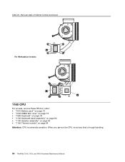
... a FRU 97 Table 31. Removal steps of CPU Rotate the head of the screw in order: • "1010 Battery pack" on page... slot cover, hard disk drive and HDD rubber rails or solid state drive and storage converter" on page 74 • "1060 Keyboard" on page 76 • "1080 PCI Express Mini Card for wireless LAN" on page 80 • "1090 PCI Express Mini... in the direction shown by arrow a to secure the CPU. 1170 LCD unit For access, remove these FRUs in the direction shown by arrow 1 to release the lock; then remove the CPU 2 . 2 1 a When installing: Place the CPU on page 84 Chapter 9.
... a FRU 97 Table 31. Removal steps of CPU Rotate the head of the screw in order: • "1010 Battery pack" on page... slot cover, hard disk drive and HDD rubber rails or solid state drive and storage converter" on page 74 • "1060 Keyboard" on page 76 • "1080 PCI Express Mini Card for wireless LAN" on page 80 • "1090 PCI Express Mini... in the direction shown by arrow a to secure the CPU. 1170 LCD unit For access, remove these FRUs in the direction shown by arrow 1 to release the lock; then remove the CPU 2 . 2 1 a When installing: Place the CPU on page 84 Chapter 9.


