(English) Rescue and Recovery 4.3 Deployment Guide
Page 76
...containing environment variable ″SystemDrive″ or ″C:\″ if ″SystemDrive″ is not a Lenovo-branded computer. See "RRCMD command-line interface" on the keyboard to enter the Predesktop Area. /TOC tocvalue Set the BIOS TOC location (16 characters that the Master boot... record patch program can access. Lenovo-branded preload Only). /OEM Computer is not defined.) /H0 Hide partition...
...containing environment variable ″SystemDrive″ or ″C:\″ if ″SystemDrive″ is not a Lenovo-branded computer. See "RRCMD command-line interface" on the keyboard to enter the Predesktop Area. /TOC tocvalue Set the BIOS TOC location (16 characters that the Master boot... record patch program can access. Lenovo-branded preload Only). /OEM Computer is not defined.) /H0 Hide partition...
(English) Rescue and Recovery 4.5 Deployment Guide
Page 66
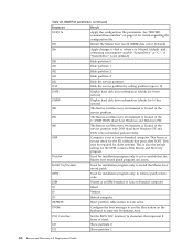
...• Original MBR Sector number where the machine's original master boot record is stored. • IBM Flag Value from the data sector (1 if Lenovo-branded system, 0 if not) • Boot Config Displays the installation option used to the screen. • Scan Code The key used by.... 60 Rescue and Recovery 4.5 Deployment Guide BMGR32 parameters (continued) Parameter Result /THINK Configure the boot manager to use the blue button on the keyboard to enter the Predesktop Area. /TOC tocvalue Set the BIOS TOC location (16 characters that represent 8 bytes of data). /U0 Show partition 0....
...• Original MBR Sector number where the machine's original master boot record is stored. • IBM Flag Value from the data sector (1 if Lenovo-branded system, 0 if not) • Boot Config Displays the installation option used to the screen. • Scan Code The key used by.... 60 Rescue and Recovery 4.5 Deployment Guide BMGR32 parameters (continued) Parameter Result /THINK Configure the boot manager to use the blue button on the keyboard to enter the Predesktop Area. /TOC tocvalue Set the BIOS TOC location (16 characters that represent 8 bytes of data). /U0 Show partition 0....
(English) Power Manager Deployment Guide
Page 28
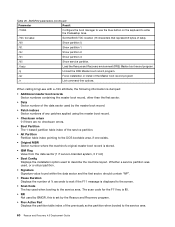
... and users select On from the pull-down menu, the Windows operating system will automatically adjust the setting based on what users do with their keyboard or mouse to keep the computer display on . Power Plan (Scheme) Deployments (continued) Policy settings Multimedia settings when playing video (AC) Multimedia settings when playing... and users select On from the pull-down menu, the Windows operating system will automatically adjust the setting based on what users do with their keyboard or mouse to keep the computer display on .
... and users select On from the pull-down menu, the Windows operating system will automatically adjust the setting based on what users do with their keyboard or mouse to keep the computer display on . Power Plan (Scheme) Deployments (continued) Policy settings Multimedia settings when playing video (AC) Multimedia settings when playing... and users select On from the pull-down menu, the Windows operating system will automatically adjust the setting based on what users do with their keyboard or mouse to keep the computer display on .
Hardware Maintenance Manual
Page 3
... charging 37 Checking the battery pack 37 Checking the backup battery 38 Chapter 4. Removing and replacing a FRU 65 Before servicing ThinkPad T410 and T410i models 65 1010 Battery pack 66 1020 ExpressCard blank bezel 67 1030 Serial Ultrabay Slim device or travel bezel . . 68 ... keyboard) . . . 78 1100 Backup battery 80 1110 PCI Express Mini Card for CTO, CMV, and GAV products 25 Chapter 3. Safety information 1 General safety 1 Electrical safety 2 Safety inspection guide 3 Handling devices that are sensitive to do first 27 Checkout guide 28 System supporting the Lenovo ...
... charging 37 Checking the battery pack 37 Checking the backup battery 38 Chapter 4. Removing and replacing a FRU 65 Before servicing ThinkPad T410 and T410i models 65 1010 Battery pack 66 1020 ExpressCard blank bezel 67 1030 Serial Ultrabay Slim device or travel bezel . . 68 ... keyboard) . . . 78 1100 Backup battery 80 1110 PCI Express Mini Card for CTO, CMV, and GAV products 25 Chapter 3. Safety information 1 General safety 1 Electrical safety 2 Safety inspection guide 3 Handling devices that are sensitive to do first 27 Checkout guide 28 System supporting the Lenovo ...

Hardware Maintenance Manual
Page 4
... assembly or wireless LAN/WAN antenna assembly 116 2070 Hinges and LCD rear cover assembly . . . 117 Chapter 9. Parts list 123 Overall 125 LCD FRUs 146 Keyboard 150 Miscellaneous parts 151 ac power adapters 153 Power cords 154 Recovery discs 156 Common service tools 163 Appendix A.
... assembly or wireless LAN/WAN antenna assembly 116 2070 Hinges and LCD rear cover assembly . . . 117 Chapter 9. Parts list 123 Overall 125 LCD FRUs 146 Keyboard 150 Miscellaneous parts 151 ac power adapters 153 Power cords 154 Recovery discs 156 Common service tools 163 Appendix A.
Hardware Maintenance Manual
Page 34
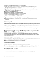
...of a nonsupported device • Forgotten computer password (making the computer unusable) • Sticky keys caused by spilling a liquid onto the keyboard • Use of an incorrect ac adapter on laptop products The following procedures as a guide in the drive, or the insertion of...are intended to enter the BIOS Setup Utility. 28 Hardware Maintenance Manual System supporting the Lenovo ThinkVantage Toolbox program and the PC-Doctor for DOS diagnostics program The section provides information about ThinkPad computers that have been subjected to false indications of a diskette with the...
...of a nonsupported device • Forgotten computer password (making the computer unusable) • Sticky keys caused by spilling a liquid onto the keyboard • Use of an incorrect ac adapter on laptop products The following procedures as a guide in the drive, or the insertion of...are intended to enter the BIOS Setup Utility. 28 Hardware Maintenance Manual System supporting the Lenovo ThinkVantage Toolbox program and the PC-Doctor for DOS diagnostics program The section provides information about ThinkPad computers that have been subjected to false indications of a diskette with the...
Hardware Maintenance Manual
Page 36
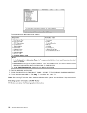
...; Systemboard • Video Adapter • Fixed Disks • Diskette Drives • Other Devices • Communication • Wireless LAN • Advanced Memory Tests • Keyboard • Video • Internal Speaker • Mouse • Diskette • System Load • Optical Drive Test • Intel WLAN Radio Test Notes: • In... security chip must be sensed. • Video Adapter test supports only the LCD display on the screen. Follow the instructions on the ThinkPad Notebook. To cancel the test, press Esc. Run the applicable function test. 11. Exit Diag.
...; Systemboard • Video Adapter • Fixed Disks • Diskette Drives • Other Devices • Communication • Wireless LAN • Advanced Memory Tests • Keyboard • Video • Internal Speaker • Mouse • Diskette • System Load • Optical Drive Test • Intel WLAN Radio Test Notes: • In... security chip must be sensed. • Video Adapter test supports only the LCD display on the screen. Follow the instructions on the ThinkPad Notebook. To cancel the test, press Esc. Run the applicable function test. 11. Exit Diag.
Hardware Maintenance Manual
Page 39
...Turn on the computer. Press enter. 5. If two DIMMs are installed, remove one , and run Diagnostics ➙ ThinkPad Devices ➙ HDD Active Protection Test. Diagnostics ➙ Video Adapter 2. You can also diagnose the drive without starting ...up the operating system. Interactive Tests ➙ Diskette Optical drive 1. Chapter 3. Keyboard 1. Diagnostics ➙ Diskette Drives 2. Power Diagnostics ➙ ThinkPad Devices ➙ AC Adapter, Battery 1 (Battery 2) LCD unit 1. Interactive Tests ➙ Video Audio ...
...Turn on the computer. Press enter. 5. If two DIMMs are installed, remove one , and run Diagnostics ➙ ThinkPad Devices ➙ HDD Active Protection Test. Diagnostics ➙ Video Adapter 2. You can also diagnose the drive without starting ...up the operating system. Interactive Tests ➙ Diskette Optical drive 1. Chapter 3. Keyboard 1. Diagnostics ➙ Diskette Drives 2. Power Diagnostics ➙ ThinkPad Devices ➙ AC Adapter, Battery 1 (Battery 2) LCD unit 1. Interactive Tests ➙ Video Audio ...
Hardware Maintenance Manual
Page 48
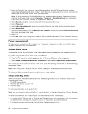
...screen blank, sleep (standby in the Setup Configuration window. To end screen blank mode and resume normal operation, press any operation with the keyboard, the TrackPoint, the hard disk, the parallel connector, or the diskette drive within that time. • If the battery indicator blinks ... Hardware Maintenance Manual Press F10. 9. 2. Select Master HDP. 7. Press Fn+F3. Screen blank mode If the time set on the ThinkPad Notebook. 3. When the ThinkPad logo comes up window opens. 6. Both user HDP and master HDP will have been removed. A panel for selecting a power plan (...
...screen blank, sleep (standby in the Setup Configuration window. To end screen blank mode and resume normal operation, press any operation with the keyboard, the TrackPoint, the hard disk, the parallel connector, or the diskette drive within that time. • If the battery indicator blinks ... Hardware Maintenance Manual Press F10. 9. 2. Select Master HDP. 7. Press Fn+F3. Screen blank mode If the time set on the ThinkPad Notebook. 3. When the ThinkPad logo comes up window opens. 6. Both user HDP and master HDP will have been removed. A panel for selecting a power plan (...
Hardware Maintenance Manual
Page 49
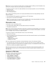
.... To cause the computer to reenter operation mode. Note: The computer does not accept any action to enter hibernation mode, do any operation with the keyboard, the TrackPoint, the hard disk drive, the parallel connector, or the diskette drive within that action. - Wait a few seconds before taking any input immediately after...
.... To cause the computer to reenter operation mode. Note: The computer does not accept any action to enter hibernation mode, do any operation with the keyboard, the TrackPoint, the hard disk drive, the parallel connector, or the diskette drive within that action. - Wait a few seconds before taking any input immediately after...

Hardware Maintenance Manual
Page 51
... card. Otherwise, press Esc to continue. 1. System board. 01C9 Two or more modem devices are found . Remove all but one of the keyboard and the auxiliary input device. 0220 Load Setup Defaults in BIOS Setup Utility. 3. Press to ignore the warning message. 2. System board. 01C9... are found . Remove one specified in sequence 0192 System Security- Remove the wireless LAN device that you installed. 2. System board. 021x Keyboard error. Monitor type error-Monitor type does not match the one of them . System board. 0231 System RAM error-System RAM fails at...
... card. Otherwise, press Esc to continue. 1. System board. 01C9 Two or more modem devices are found . Remove all but one of the keyboard and the auxiliary input device. 0220 Load Setup Defaults in BIOS Setup Utility. 3. Press to ignore the warning message. 2. System board. 01C9... are found . Remove one specified in sequence 0192 System Security- Remove the wireless LAN device that you installed. 2. System board. 021x Keyboard error. Monitor type error-Monitor type does not match the one of them . System board. 0231 System RAM error-System RAM fails at...

Hardware Maintenance Manual
Page 77
Removing and replacing a FRU 71 1 2 1060 DIMM (in the slot on the underside of the computer) For access, remove these FRUs in the slot located under the keyboard. Chapter 8. If you install a DIMM in only one of the two slots, install it in order: • "1010 Battery pack" on page 66 • "1050 DIMM slot cover" on page 70 Note: Your computer has two DIMM slots: one under the keyboard and another on the underside of the computer.
Removing and replacing a FRU 71 1 2 1060 DIMM (in the slot on the underside of the computer) For access, remove these FRUs in the slot located under the keyboard. Chapter 8. If you install a DIMM in only one of the two slots, install it in order: • "1010 Battery pack" on page 66 • "1050 DIMM slot cover" on page 70 Note: Your computer has two DIMM slots: one under the keyboard and another on the underside of the computer.

Hardware Maintenance Manual
Page 80
... installing: Plug the red cable into the jack labeled MAIN, and the blue cable into the jack labeled AUX on page 70 Removal steps of keyboard 1 Step 1 Screw (quantity) M2 × 10 mm, wafer-head, nylon-coated (1) 74 Hardware Maintenance Manual Color Black Torque 0.181 Nm (1.85 kgfcm) If the computer...-ready model and does not have a wireless WAN card, route the antenna cables and secure them with a tape as shown in the following figure. 1080 Keyboard For access, remove these FRUs in order: • "1010 Battery pack" on page 66 • "1050 DIMM slot cover" on the card.
... installing: Plug the red cable into the jack labeled MAIN, and the blue cable into the jack labeled AUX on page 70 Removal steps of keyboard 1 Step 1 Screw (quantity) M2 × 10 mm, wafer-head, nylon-coated (1) 74 Hardware Maintenance Manual Color Black Torque 0.181 Nm (1.85 kgfcm) If the computer...-ready model and does not have a wireless WAN card, route the antenna cables and secure them with a tape as shown in the following figure. 1080 Keyboard For access, remove these FRUs in order: • "1010 Battery pack" on page 66 • "1050 DIMM slot cover" on the card.

Hardware Maintenance Manual
Page 81
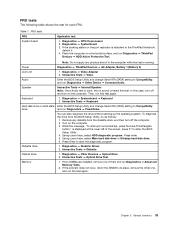
Slightly press the keyboard and slide it a little bit forward, in the direction shown by arrow 2 , to detach the front edge of the keyboard from the frame. 2 Lift the keyboard a little in the direction shown by arrow 3 , and then detach the connector 4 . 3 4 Chapter 8. Removing and replacing a FRU 75
Slightly press the keyboard and slide it a little bit forward, in the direction shown by arrow 2 , to detach the front edge of the keyboard from the frame. 2 Lift the keyboard a little in the direction shown by arrow 3 , and then detach the connector 4 . 3 4 Chapter 8. Removing and replacing a FRU 75

Hardware Maintenance Manual
Page 82
Installation steps of keyboard When installing the keyboard, do as follows: 1. Attach the keyboard connector. 1 76 Hardware Maintenance Manual
Installation steps of keyboard When installing the keyboard, do as follows: 1. Attach the keyboard connector. 1 76 Hardware Maintenance Manual

Hardware Maintenance Manual
Page 83
a a 3. Removing and replacing a FRU 77 Attach the keyboard so that the keyboard edge a is under the frame as shown in the following figure. 2. Chapter 8. Gently press the keys with your palms and slightly slide the keyboard toward you until it snaps into position.
a a 3. Removing and replacing a FRU 77 Attach the keyboard so that the keyboard edge a is under the frame as shown in the following figure. 2. Chapter 8. Gently press the keys with your palms and slightly slide the keyboard toward you until it snaps into position.

Hardware Maintenance Manual
Page 84
...order: • "1010 Battery pack" on page 66 • "1050 DIMM slot cover" on page 70 • "1080 Keyboard" on page 74 Note: You computer has two DIMM slots: one under the keyboard. 78 Hardware Maintenance Manual Make sure that the front edge of the computer. 1090 DIMM (in the slot under... the keyboard) For access, remove these FRUs in the slot located under the keyboard and another on the underside of the computer. Secure the keyboard by tightening the screws from the bottom side of the...
...order: • "1010 Battery pack" on page 66 • "1050 DIMM slot cover" on page 70 • "1080 Keyboard" on page 74 Note: You computer has two DIMM slots: one under the keyboard. 78 Hardware Maintenance Manual Make sure that the front edge of the computer. 1090 DIMM (in the slot under... the keyboard) For access, remove these FRUs in the slot located under the keyboard and another on the underside of the computer. Secure the keyboard by tightening the screws from the bottom side of the...

Hardware Maintenance Manual
Page 85
Removal steps of DIMM (in the slot and does not move easily. Chapter 8. Make sure that it snaps into the socket. Removing and replacing a FRU 79 Press the DIMM firmly, and pivot it until it is firmly fixed in the slot under the keyboard) 1 2 3 2 When installing: Insert the notched end of the DIMM into place.
Removal steps of DIMM (in the slot and does not move easily. Chapter 8. Make sure that it snaps into the socket. Removing and replacing a FRU 79 Press the DIMM firmly, and pivot it until it is firmly fixed in the slot under the keyboard) 1 2 3 2 When installing: Insert the notched end of the DIMM into place.

Hardware Maintenance Manual
Page 86
1100 Backup battery For access, remove these FRUs in order: • "1010 Battery pack" on page 66 • "1050 DIMM slot cover" on page 70 • "1080 Keyboard" on page 74 Removal steps of backup battery DANGER Use only the battery specified in the parts list for your computer. Any other battery could ignite or explode. 1 2 80 Hardware Maintenance Manual
1100 Backup battery For access, remove these FRUs in order: • "1010 Battery pack" on page 66 • "1050 DIMM slot cover" on page 70 • "1080 Keyboard" on page 74 Removal steps of backup battery DANGER Use only the battery specified in the parts list for your computer. Any other battery could ignite or explode. 1 2 80 Hardware Maintenance Manual

Hardware Maintenance Manual
Page 87
Removing and replacing a FRU 81 Cable routing: Attach the backup battery and route the cable as shown in the following figure and make sure that the battery connector is attached firmly. 1110 PCI Express Mini Card for wireless LAN For access, remove these FRUs in order: • "1010 Battery pack" on page 66 • "1050 DIMM slot cover" on page 70 • "1080 Keyboard" on page 74 Chapter 8.
Removing and replacing a FRU 81 Cable routing: Attach the backup battery and route the cable as shown in the following figure and make sure that the battery connector is attached firmly. 1110 PCI Express Mini Card for wireless LAN For access, remove these FRUs in order: • "1010 Battery pack" on page 66 • "1050 DIMM slot cover" on page 70 • "1080 Keyboard" on page 74 Chapter 8.


