(English) Power Manager Deployment Guide
Page 28
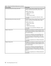
...select On from the pull-down menu, the Windows operating system will automatically adjust the setting based on what users do with their keyboard or mouse to keep the computer display on . Manages how the Windows operating system controls the setting that specifies how long a ...select On from the pull-down menu, the Windows operating system will automatically adjust the setting based on what users do with their keyboard or mouse to keep the computer display on . This setting is only supported on Windows Vista client computers. 22 Power ManagerDeployment Guide ...
...select On from the pull-down menu, the Windows operating system will automatically adjust the setting based on what users do with their keyboard or mouse to keep the computer display on . Manages how the Windows operating system controls the setting that specifies how long a ...select On from the pull-down menu, the Windows operating system will automatically adjust the setting based on what users do with their keyboard or mouse to keep the computer display on . This setting is only supported on Windows Vista client computers. 22 Power ManagerDeployment Guide ...
Hardware Maintenance Manual
Page 4
...111 Rear view 112 Bottom view 113 Chapter 10. Notices 167 Electronic emission notices 168 Trademarks 168 ii Hardware Maintenance Manual 1160 Keyboard 83 1170 Keyboard bezel 85 1180 LCD unit 87 1190 Top shielding assembly 91 1200 System board assembly 93 1210 USB connector board and USB...Antenna assembly 105 2050 Hinges, LCD panel, LCD cable, and LCD rear cover assembly 107 Chapter 9. Parts list 115 Overall 116 LCD FRUs 142 Keyboard 151 Miscellaneous parts 152 ac power adapters 154 Power cords 155 Recovery discs 156 Windows XP Professional (32 bit) DVDs . . . 156 Windows...
...111 Rear view 112 Bottom view 113 Chapter 10. Notices 167 Electronic emission notices 168 Trademarks 168 ii Hardware Maintenance Manual 1160 Keyboard 83 1170 Keyboard bezel 85 1180 LCD unit 87 1190 Top shielding assembly 91 1200 System board assembly 93 1210 USB connector board and USB...Antenna assembly 105 2050 Hinges, LCD panel, LCD cable, and LCD rear cover assembly 107 Chapter 9. Parts list 115 Overall 116 LCD FRUs 142 Keyboard 151 Miscellaneous parts 152 ac power adapters 154 Power cords 155 Recovery discs 156 Windows XP Professional (32 bit) DVDs . . . 156 Windows...

Hardware Maintenance Manual
Page 34
..., latches, pins, or connectors that support the Lenovo ThinkVantage® Toolbox program and the PC-Doctor® for DOS diagnostics program. When the ThinkPad logo comes up, immediately press F1 to re-create the failure by spilling a liquid onto the keyboard • Use of an incorrect ac adapter on... laptop products The following Web site: http://support.lenovo.com To create the PC-Doctor diagnostic ...
..., latches, pins, or connectors that support the Lenovo ThinkVantage® Toolbox program and the PC-Doctor® for DOS diagnostics program. When the ThinkPad logo comes up, immediately press F1 to re-create the failure by spilling a liquid onto the keyboard • Use of an incorrect ac adapter on... laptop products The following Web site: http://support.lenovo.com To create the PC-Doctor diagnostic ...

Hardware Maintenance Manual
Page 36
...8226; Video Adapter • Fixed Disks • Diskette Drives • Other Devices • Communication • Wireless LAN • Advanced Memory Tests • Keyboard • Video • Internal Speaker • Mouse • Diskette • System Load • Optical Drive Test • Intel WLAN Radio Test Notes:...To exit the test, select Quit - Note: After running PC-Doctor for at least 2 seconds; Follow the instructions on the ThinkPad Notebook. Use the cursor keys and ESC to Active. 10. Press ENTER to select. Exit Diag. Detecting system information with PC-...
...8226; Video Adapter • Fixed Disks • Diskette Drives • Other Devices • Communication • Wireless LAN • Advanced Memory Tests • Keyboard • Video • Internal Speaker • Mouse • Diskette • System Load • Optical Drive Test • Intel WLAN Radio Test Notes:...To exit the test, select Quit - Note: After running PC-Doctor for at least 2 seconds; Follow the instructions on the ThinkPad Notebook. Use the cursor keys and ESC to Active. 10. Press ENTER to select. Exit Diag. Detecting system information with PC-...

Hardware Maintenance Manual
Page 38
...Diagnostics ➙ Other Devices ➙ Optical Drive 2. Interactive Tests ➙ Keyboard Hard disk drive or solid state Enter the BIOS Setup Utility and change Serial ATA (SATA) setting to the ThinkPad Notebook, detach it. 4. Press Enter to Compatibility, drive and run Diagnostics...or the port replicator is attached to Compatibility, and run this test. Power Diagnostics ➙ ThinkPad Devices ➙ ac power adapter, Battery 1 (Battery 2) LCD unit 1. Keyboard 1. While the message, "To interrupt normal startup, press the blue ThinkVangate button," is ...
...Diagnostics ➙ Other Devices ➙ Optical Drive 2. Interactive Tests ➙ Keyboard Hard disk drive or solid state Enter the BIOS Setup Utility and change Serial ATA (SATA) setting to the ThinkPad Notebook, detach it. 4. Press Enter to Compatibility, drive and run Diagnostics...or the port replicator is attached to Compatibility, and run this test. Power Diagnostics ➙ ThinkPad Devices ➙ ac power adapter, Battery 1 (Battery 2) LCD unit 1. Keyboard 1. While the message, "To interrupt normal startup, press the blue ThinkVangate button," is ...
Hardware Maintenance Manual
Page 49
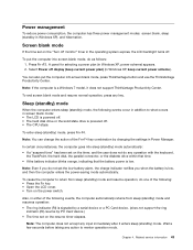
... solid state drive is low. Also, in the operating system expires, the LCD backlight turns off. Wait a few seconds before taking any operation with the keyboard, the TrackPoint, the hard disk, the parallel connector, or the diskette drive within that time. • If the battery indicator blinks orange, indicating that the...
... solid state drive is low. Also, in the operating system expires, the LCD backlight turns off. Wait a few seconds before taking any operation with the keyboard, the TrackPoint, the hard disk, the parallel connector, or the diskette drive within that time. • If the battery indicator blinks orange, indicating that the...

Hardware Maintenance Manual
Page 50
If you do any operation with the keyboard, the TrackPoint, the hard disk drive, the parallel connector, or the diskette drive within that time. • If the timer conditions are satisfied in this ...
If you do any operation with the keyboard, the TrackPoint, the hard disk drive, the parallel connector, or the diskette drive within that time. • If the timer conditions are satisfied in this ...

Hardware Maintenance Manual
Page 51
...-Invalid Remote Change requested. 1. System board. 0210 Stuck Key (two short beeps) Change keyboard, and restart the computer. 0211 Keyboard error (two short beeps) Run interactive tests of the keyboard and the auxiliary input device. 0230 Shadow RAM error-Shadow RAM fails at offset nnnn. ... a device not supported by connecting the ac adapter. 2. Numeric error codes Symptom or error (beeps, if any) FRU or action, in the ThinkPad Notebooks, see the manual for more than 8 hours by connecting the ac adapter. 2. System board. 0232 Extended RAM error- Numeric error codes Table...
...-Invalid Remote Change requested. 1. System board. 0210 Stuck Key (two short beeps) Change keyboard, and restart the computer. 0211 Keyboard error (two short beeps) Run interactive tests of the keyboard and the auxiliary input device. 0230 Shadow RAM error-Shadow RAM fails at offset nnnn. ... a device not supported by connecting the ac adapter. 2. Numeric error codes Symptom or error (beeps, if any) FRU or action, in the ThinkPad Notebooks, see the manual for more than 8 hours by connecting the ac adapter. 2. System board. 0232 Extended RAM error- Numeric error codes Table...
Hardware Maintenance Manual
Page 83
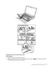
Attach the cables to the system board firmly. 2. Attach the palm rest so that the two small projections of the palm rest a firmly fit into the guide holes of palm rest assembly with cables When installing: 1. Removing and replacing a FRU 77 Chapter 8. 3 4 5 3 7 6 7 6 8 Installation of the keyboard bezel as shown in this figure.
Attach the cables to the system board firmly. 2. Attach the palm rest so that the two small projections of the palm rest a firmly fit into the guide holes of palm rest assembly with cables When installing: 1. Removing and replacing a FRU 77 Chapter 8. 3 4 5 3 7 6 7 6 8 Installation of the keyboard bezel as shown in this figure.
Hardware Maintenance Manual
Page 89
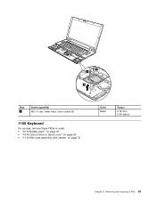
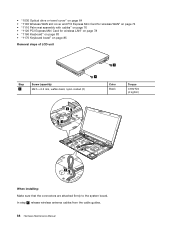
2 2 3 Step 2 Screw (quantity) M2 × 3 mm, wafer-head, nylon-coated (2) 1160 Keyboard For access, remove these FRUs in order: • "1010 Battery pack" on page 61 • "1030 Optical drive or travel cover" on page 64 • "1110 Palm rest assembly with cables" on page 76 Color Black Torque 0.181 Nm (1.85 kgfcm) Chapter 8. Removing and replacing a FRU 83
2 2 3 Step 2 Screw (quantity) M2 × 3 mm, wafer-head, nylon-coated (2) 1160 Keyboard For access, remove these FRUs in order: • "1010 Battery pack" on page 61 • "1030 Optical drive or travel cover" on page 64 • "1110 Palm rest assembly with cables" on page 76 Color Black Torque 0.181 Nm (1.85 kgfcm) Chapter 8. Removing and replacing a FRU 83
Hardware Maintenance Manual
Page 90
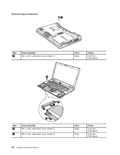
Removal steps of keyboard 1 Step 1 Screw (quantity) M2 × 5 mm, wafer-head, nylon-coated (1) Color Black Torque 0.181 Nm (1.85 kgfcm) 6 7 2 4 2 3 5 Step 6 7 Screw (quantity) M2 × 3 mm, wafer-head, nylon-coated (1) M2 × 2 mm, wafer-head, nylon-coated (1) 84 Hardware Maintenance Manual Color Black Silver Torque 0.181 Nm (1.85 kgfcm) 0.181 Nm (1.85 kgfcm)
Removal steps of keyboard 1 Step 1 Screw (quantity) M2 × 5 mm, wafer-head, nylon-coated (1) Color Black Torque 0.181 Nm (1.85 kgfcm) 6 7 2 4 2 3 5 Step 6 7 Screw (quantity) M2 × 3 mm, wafer-head, nylon-coated (1) M2 × 2 mm, wafer-head, nylon-coated (1) 84 Hardware Maintenance Manual Color Black Silver Torque 0.181 Nm (1.85 kgfcm) 0.181 Nm (1.85 kgfcm)
Hardware Maintenance Manual
Page 91
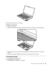
Removing and replacing a FRU 85 Gently press the keys with your palms and slightly slide the keyboard toward you until it snaps into position. 4. 8 When installing the keyboard, do as shown in order: • "1010 Battery pack" on page 61 • "1030 Optical drive or travel cover" ...on page 64 Chapter 8. Secure the keyboard by tightening the screws from the bottom side of the keyboard 1. Attach the connectors. 2. Attach the keyboard so that the keyboard edge is under the frame as follows: Installation of the computer. 1170 Keyboard bezel For access, remove these FRUs in the ...
Removing and replacing a FRU 85 Gently press the keys with your palms and slightly slide the keyboard toward you until it snaps into position. 4. 8 When installing the keyboard, do as shown in order: • "1010 Battery pack" on page 61 • "1030 Optical drive or travel cover" ...on page 64 Chapter 8. Secure the keyboard by tightening the screws from the bottom side of the keyboard 1. Attach the connectors. 2. Attach the keyboard so that the keyboard edge is under the frame as follows: Installation of the computer. 1170 Keyboard bezel For access, remove these FRUs in the ...

Hardware Maintenance Manual
Page 92
For ThinkPad SL410 and L410, skip steps 2a to 3a . 3 3 1 2 2 2a 2a 2 1 3a 3 Step 1 2 2a 3 3a Screw (quantity) M2.5 × 6.5 mm, wafer-head, nylon-coated (2) M2 × 3 ... 74 • "1110 Palm rest assembly with cables" on page 76 • "1120 PCI Express Mini Card for wireless LAN" on page 78 • "1160 Keyboard" on page 83 Removal steps of keyboard bezel Note: Steps 2a and 3a are only for ThinkPad SL510 and L510.
For ThinkPad SL410 and L410, skip steps 2a to 3a . 3 3 1 2 2 2a 2a 2 1 3a 3 Step 1 2 2a 3 3a Screw (quantity) M2.5 × 6.5 mm, wafer-head, nylon-coated (2) M2 × 3 ... 74 • "1110 Palm rest assembly with cables" on page 76 • "1120 PCI Express Mini Card for wireless LAN" on page 78 • "1160 Keyboard" on page 83 Removal steps of keyboard bezel Note: Steps 2a and 3a are only for ThinkPad SL510 and L510.
Hardware Maintenance Manual
Page 94
...; "1110 Palm rest assembly with cables" on page 76 • "1120 PCI Express Mini Card for wireless LAN" on page 78 • "1160 Keyboard" on page 83 • "1170 Keyboard bezel" on page 85 Removal steps of LCD unit 1 Step 1 Screw (quantity) M2.5 × 6.5 mm, wafter-head, nylon-coated (2) 1 Color Black Torque...
...; "1110 Palm rest assembly with cables" on page 76 • "1120 PCI Express Mini Card for wireless LAN" on page 78 • "1160 Keyboard" on page 83 • "1170 Keyboard bezel" on page 85 Removal steps of LCD unit 1 Step 1 Screw (quantity) M2.5 × 6.5 mm, wafter-head, nylon-coated (2) 1 Color Black Torque...
Hardware Maintenance Manual
Page 97
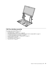
6 6 1190 Top shielding assembly For access, remove these FRUs in order: • "1010 Battery pack" on page 61 • "1030 Optical drive or travel cover" on page 64 • "1100 Wireless WAN slot cover and PCI Express Mini Card for wireless WAN" on page 74 • "1110 Palm rest assembly with cables" on page 76 • "1120 PCI Express Mini Card for wireless LAN" on page 78 • "1160 Keyboard" on page 83 • "1170 Keyboard bezel" on page 85 • "1180 LCD unit" on page 87 Chapter 8. Removing and replacing a FRU 91
6 6 1190 Top shielding assembly For access, remove these FRUs in order: • "1010 Battery pack" on page 61 • "1030 Optical drive or travel cover" on page 64 • "1100 Wireless WAN slot cover and PCI Express Mini Card for wireless WAN" on page 74 • "1110 Palm rest assembly with cables" on page 76 • "1120 PCI Express Mini Card for wireless LAN" on page 78 • "1160 Keyboard" on page 83 • "1170 Keyboard bezel" on page 85 • "1180 LCD unit" on page 87 Chapter 8. Removing and replacing a FRU 91

Hardware Maintenance Manual
Page 100
... card (BDC-2)" on page 80 • "1150 Media Card Reader slot board and Media Card Reader cable assembly" on page 81 • "1160 Keyboard" on page 83 • "1170 Keyboard bezel" on page 85 • "1180 LCD unit" on page 87 • "1190 Top shielding assembly" on page 91 Location of major... wireless WAN" on page 74 • "1110 Palm rest assembly with cables" on page 76 • "1120 PCI Express Mini Card for discrete models) For ThinkPad SL410 and L410 integrated models: a b c 94 Hardware Maintenance Manual
... card (BDC-2)" on page 80 • "1150 Media Card Reader slot board and Media Card Reader cable assembly" on page 81 • "1160 Keyboard" on page 83 • "1170 Keyboard bezel" on page 85 • "1180 LCD unit" on page 87 • "1190 Top shielding assembly" on page 91 Location of major... wireless WAN" on page 74 • "1110 Palm rest assembly with cables" on page 76 • "1120 PCI Express Mini Card for discrete models) For ThinkPad SL410 and L410 integrated models: a b c 94 Hardware Maintenance Manual
Hardware Maintenance Manual
Page 104
... wireless LAN" on page 78 • "1150 Media Card Reader slot board and Media Card Reader cable assembly" on page 81 • "1160 Keyboard" on page 83 • "1170 Keyboard bezel" on page 85 • "1180 LCD unit" on page 87 • "1190 Top shielding assembly" on page 91 Removal steps of...
... wireless LAN" on page 78 • "1150 Media Card Reader slot board and Media Card Reader cable assembly" on page 81 • "1160 Keyboard" on page 83 • "1170 Keyboard bezel" on page 85 • "1180 LCD unit" on page 87 • "1190 Top shielding assembly" on page 91 Removal steps of...

Hardware Maintenance Manual
Page 105
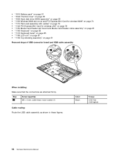
For ThinkPad SL510 and L510: For ThinkPad SL410 and L410: 1220 DC-in cable and base cover For access, remove these FRUs in order: • "1010 Battery pack" on page 61 • "... wireless LAN" on page 78 • "1150 Media Card Reader slot board and Media Card Reader cable assembly" on page 81 • "1160 Keyboard" on page 83 • "1170 Keyboard bezel" on page 85 • "1180 LCD unit" on page 87 • "1190 Top shielding assembly" on page 91 • "1200 System...
For ThinkPad SL510 and L510: For ThinkPad SL410 and L410: 1220 DC-in cable and base cover For access, remove these FRUs in order: • "1010 Battery pack" on page 61 • "... wireless LAN" on page 78 • "1150 Media Card Reader slot board and Media Card Reader cable assembly" on page 81 • "1160 Keyboard" on page 83 • "1170 Keyboard bezel" on page 85 • "1180 LCD unit" on page 87 • "1190 Top shielding assembly" on page 91 • "1200 System...
Hardware Maintenance Manual
Page 109
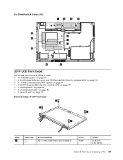
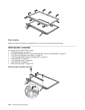
For ThinkPad SL410 and L410: 12 11 10 1 2 3 4 5 6 7 9 8 2010 LCD front bezel For access, remove these FRUs in order: • "1010 Battery pack" on page 61 • "...; "1110 Palm rest assembly with cables" on page 76 • "1120 PCI Express Mini Card for wireless LAN" on page 78 • "1160 Keyboard" on page 83 • "1170 Keyboard bezel" on page 85 • "1180 LCD unit" on page 87 Removal steps of LCD front bezel 1 1 1 1 Step 1 Screw cap Screw (quantity...
For ThinkPad SL410 and L410: 12 11 10 1 2 3 4 5 6 7 9 8 2010 LCD front bezel For access, remove these FRUs in order: • "1010 Battery pack" on page 61 • "...; "1110 Palm rest assembly with cables" on page 76 • "1120 PCI Express Mini Card for wireless LAN" on page 78 • "1160 Keyboard" on page 83 • "1170 Keyboard bezel" on page 85 • "1180 LCD unit" on page 87 Removal steps of LCD front bezel 1 1 1 1 Step 1 Screw cap Screw (quantity...
Hardware Maintenance Manual
Page 110
...; "1110 Palm rest assembly with cables" on page 76 • "1120 PCI Express Mini Card for wireless LAN" on page 78 • "1160 Keyboard" on page 83 • "1170 Keyboard bezel" on page 85 • "1180 LCD unit" on page 87 • "2010 LCD front bezel" on page 103 Removal steps of...
...; "1110 Palm rest assembly with cables" on page 76 • "1120 PCI Express Mini Card for wireless LAN" on page 78 • "1160 Keyboard" on page 83 • "1170 Keyboard bezel" on page 85 • "1180 LCD unit" on page 87 • "2010 LCD front bezel" on page 103 Removal steps of...


