Hardware Maintenance Manual
Page 38
... discharges quickly after recharging, replace the battery. 4. Turn the computer upside down. 3. See the following : 1. Checking the backup battery Do the following figure. Wire Red Black Voltage (V dc) +2.5 to +3.2 Ground • If the voltage is correct, replace the system board. • If the voltage is still less than +11.0 V dc after...
... discharges quickly after recharging, replace the battery. 4. Turn the computer upside down. 3. See the following : 1. Checking the backup battery Do the following figure. Wire Red Black Voltage (V dc) +2.5 to +3.2 Ground • If the voltage is correct, replace the system board. • If the voltage is still less than +11.0 V dc after...
Hardware Maintenance Manual
Page 61
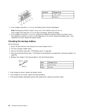
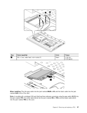
..., have the user make a backup copy of hard disk drive or solid state drive 1 1 2 Step 1 Screw (quantity) M2 × 5 mm, wafer-head, nylon-coated (2) 3 Color Black Torque 0.181 Nm (1.85 kgfcm) When installing: Make sure the hard disk drive or solid state drive assembly is sensitive to it if possible. •...
..., have the user make a backup copy of hard disk drive or solid state drive 1 1 2 Step 1 Screw (quantity) M2 × 5 mm, wafer-head, nylon-coated (2) 3 Color Black Torque 0.181 Nm (1.85 kgfcm) When installing: Make sure the hard disk drive or solid state drive assembly is sensitive to it if possible. •...
Hardware Maintenance Manual
Page 62
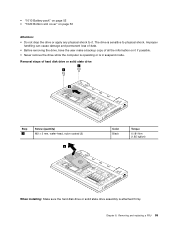
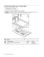
... Maintenance Manual Removal steps of the hard disk drive or solid state drive bracket 1 1 2 Step 1 Screw (quantity) M3 × 2.8 mm, wafer-head, nylon-coated (2) Color Black Torque 0.392 Nm (4 kgfcm) 1050 PCI Express Mini Card for wireless LAN For access, remove these FRUs in order: • "1010 Battery pack" on page...
... Maintenance Manual Removal steps of the hard disk drive or solid state drive bracket 1 1 2 Step 1 Screw (quantity) M3 × 2.8 mm, wafer-head, nylon-coated (2) Color Black Torque 0.392 Nm (4 kgfcm) 1050 PCI Express Mini Card for wireless LAN For access, remove these FRUs in order: • "1010 Battery pack" on page...
Hardware Maintenance Manual
Page 63
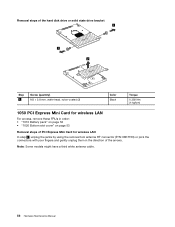
Chapter 8. Removing and replacing a FRU 57 Note: In models with a wireless LAN card that has three antenna connectors, plug the gray cable (MAIN) into the jack marked TR1, the white cable (third) into the jack marked RO or TR3, and the black cable (AUX) into the jack marked AUX or A on the card. 1 2 1 Step 2 Screw (quantity) M2 × 3 mm, wafer-head, nylon-coated (1) Color Black Torque 0.181 Nm (1.85 kgfcm) 3 When installing: Plug the gray cable into the jack marked MAIN or M, and the black cable into the jack marked TR2 on the card.
Chapter 8. Removing and replacing a FRU 57 Note: In models with a wireless LAN card that has three antenna connectors, plug the gray cable (MAIN) into the jack marked TR1, the white cable (third) into the jack marked RO or TR3, and the black cable (AUX) into the jack marked AUX or A on the card. 1 2 1 Step 2 Screw (quantity) M2 × 3 mm, wafer-head, nylon-coated (1) Color Black Torque 0.181 Nm (1.85 kgfcm) 3 When installing: Plug the gray cable into the jack marked MAIN or M, and the black cable into the jack marked TR2 on the card.
Hardware Maintenance Manual
Page 64
Step 2 Screw (quantity) M2 × 3 mm, wafer-head, nylon-coated (1) Color Black Torque 0.181 Nm (1.85 kgfcm) 58 Hardware Maintenance Manual 1060 PCI Express Mini Card for wireless WAN For access, remove these FRUs in order: • "...
Step 2 Screw (quantity) M2 × 3 mm, wafer-head, nylon-coated (1) Color Black Torque 0.181 Nm (1.85 kgfcm) 58 Hardware Maintenance Manual 1060 PCI Express Mini Card for wireless WAN For access, remove these FRUs in order: • "...
Hardware Maintenance Manual
Page 65
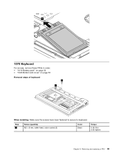
Removing and replacing a FRU 59 Step 1 Screw (quantity) M2 × 8 mm, wafer-head, nylon-coated (2) Color Black Torque 0.181 Nm (1.85 kgfcm) Chapter 8. 3 1070 Keyboard For access, remove these FRUs in order: • "1010 Battery pack" on page 52 • "1020 Bottom slot cover" on page 53 Removal steps of keyboard 1 1 When installing: Make sure the screws have been fastened to secure to keyboard.
Removing and replacing a FRU 59 Step 1 Screw (quantity) M2 × 8 mm, wafer-head, nylon-coated (2) Color Black Torque 0.181 Nm (1.85 kgfcm) Chapter 8. 3 1070 Keyboard For access, remove these FRUs in order: • "1010 Battery pack" on page 52 • "1020 Bottom slot cover" on page 53 Removal steps of keyboard 1 1 When installing: Make sure the screws have been fastened to secure to keyboard.
Hardware Maintenance Manual
Page 68
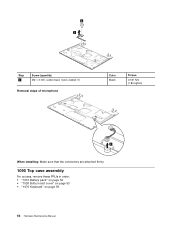
2 3 Step 2 Screw (quantity) M2 × 3 mm, wafer-head, nylon-coated (1) Removal steps of microphone Color Black Torque 0.181 Nm (1.85 kgfcm) 2 When installing: Make sure that the connectors are attached firmly. 1090 Top case assembly For access, remove these FRUs in order: • "1010 Battery pack" on page 52 • "1020 Bottom slot cover" on page 53 • "1070 Keyboard" on page 59 62 Hardware Maintenance Manual
2 3 Step 2 Screw (quantity) M2 × 3 mm, wafer-head, nylon-coated (1) Removal steps of microphone Color Black Torque 0.181 Nm (1.85 kgfcm) 2 When installing: Make sure that the connectors are attached firmly. 1090 Top case assembly For access, remove these FRUs in order: • "1010 Battery pack" on page 52 • "1020 Bottom slot cover" on page 53 • "1070 Keyboard" on page 59 62 Hardware Maintenance Manual
Hardware Maintenance Manual
Page 69
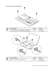
Removal steps of top case assembly 1 1 1 1 Step 1 Screw (quantity) • Front side: M2 × 5 mm, wafer-head, nylon-coated (2) • Rear side: M2.5 × 5 mm, wafer-head, nylon-coated (2) Color Black Torque 0.181 Nm (1.85 kgfcm) 2 2 2 7 5 6 Step 2 Screw (quantity) M2 × 5 mm, wafer-head, nylon-coated (3) 3 4 Color Black Torque 0.181 Nm (1.85 kgfcm) Chapter 8. Removing and replacing a FRU 63
Removal steps of top case assembly 1 1 1 1 Step 1 Screw (quantity) • Front side: M2 × 5 mm, wafer-head, nylon-coated (2) • Rear side: M2.5 × 5 mm, wafer-head, nylon-coated (2) Color Black Torque 0.181 Nm (1.85 kgfcm) 2 2 2 7 5 6 Step 2 Screw (quantity) M2 × 5 mm, wafer-head, nylon-coated (3) 3 4 Color Black Torque 0.181 Nm (1.85 kgfcm) Chapter 8. Removing and replacing a FRU 63
Hardware Maintenance Manual
Page 70
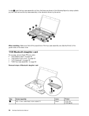
... assembly" on page 62 Removal steps of Bluetooth daughter card Step 1 Screw (quantity) M2 × 3 mm, wafer-head, nylon-coated (1) 64 Hardware Maintenance Manual 1 2 Color Black Torque 0.181 Nm (1.85 kgfcm)
... assembly" on page 62 Removal steps of Bluetooth daughter card Step 1 Screw (quantity) M2 × 3 mm, wafer-head, nylon-coated (1) 64 Hardware Maintenance Manual 1 2 Color Black Torque 0.181 Nm (1.85 kgfcm)
Hardware Maintenance Manual
Page 71
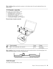
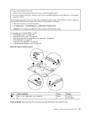
... 62 • "1100 Bluetooth daughter card" on page 64 Removal steps of speaker assembly 2 2 3 2 2 3 1 Step 2 Screw (quantity) M2 × 3 mm, wafer-head, nylon-coated (4) Color Black Torque 0.181 Nm (1.85 kgfcm) When installing: Attach the speaker assembly and route the cable as shown in the following figure, and make sure that...
... 62 • "1100 Bluetooth daughter card" on page 64 Removal steps of speaker assembly 2 2 3 2 2 3 1 Step 2 Screw (quantity) M2 × 3 mm, wafer-head, nylon-coated (4) Color Black Torque 0.181 Nm (1.85 kgfcm) When installing: Attach the speaker assembly and route the cable as shown in the following figure, and make sure that...
Hardware Maintenance Manual
Page 72
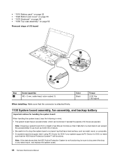
... page 59 • "1090 Top case assembly" on page 62 Removal steps of I/O board 3 4 1 2 Step 3 Screw (quantity) M2 × 3 mm, wafer-head, nylon-coated (1) Color Black Torque 0.181 Nm (1.85 kgfcm) When installing: Make sure that the connector is attached firmly. 1130 System board assembly, fan assembly, and backup battery Important...
... page 59 • "1090 Top case assembly" on page 62 Removal steps of I/O board 3 4 1 2 Step 3 Screw (quantity) M2 × 3 mm, wafer-head, nylon-coated (1) Color Black Torque 0.181 Nm (1.85 kgfcm) When installing: Make sure that the connector is attached firmly. 1130 System board assembly, fan assembly, and backup battery Important...
Hardware Maintenance Manual
Page 73
... as follows: 1. Run Diagnostics ➙ ThinkPad Devices ➙ HDD Active Protection Test. Removing and replacing a FRU 67 Attention: Do not apply physical shock to the system board. Chapter 8. • Avoid rough handling of system board 2 1 1 3 4 7 5 6 Step 1 Screw (quantity) M2 × 3 mm, wafer-head, nylon-coated (2) Color Black Torque 0.181 Nm (1.85 kgfcm...
... as follows: 1. Run Diagnostics ➙ ThinkPad Devices ➙ HDD Active Protection Test. Removing and replacing a FRU 67 Attention: Do not apply physical shock to the system board. Chapter 8. • Avoid rough handling of system board 2 1 1 3 4 7 5 6 Step 1 Screw (quantity) M2 × 3 mm, wafer-head, nylon-coated (2) Color Black Torque 0.181 Nm (1.85 kgfcm...
Hardware Maintenance Manual
Page 75
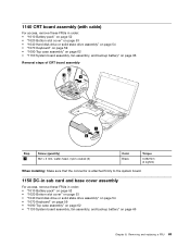
... assembly, and backup battery" on page 66 Removal steps of CRT board assembly 23 3 4 1 2 Step 3 Screw (quantity) M2 × 3 mm, wafer-head, nylon-coated (2) Color Black Torque 0.392 Nm (4 kgfcm) When installing: Make sure that the connector is attached firmly to the system board. 1150 DC-in sub card and base...
... assembly, and backup battery" on page 66 Removal steps of CRT board assembly 23 3 4 1 2 Step 3 Screw (quantity) M2 × 3 mm, wafer-head, nylon-coated (2) Color Black Torque 0.392 Nm (4 kgfcm) When installing: Make sure that the connector is attached firmly to the system board. 1150 DC-in sub card and base...

Hardware Maintenance Manual
Page 79
Removing and replacing a FRU 73 2 2 1 1 1 1 Step 3 Screw (quantity) M2.5 × 5 mm, wafer-head, nylon-coated (4) Color Black 2 2 2 2 2 2 2 2 2 2 2 Torque 0.392 Nm (4 kgfcm) Chapter 8.
Removing and replacing a FRU 73 2 2 1 1 1 1 Step 3 Screw (quantity) M2.5 × 5 mm, wafer-head, nylon-coated (4) Color Black 2 2 2 2 2 2 2 2 2 2 2 Torque 0.392 Nm (4 kgfcm) Chapter 8.
Hardware Maintenance Manual
Page 80
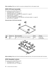
... Bottom slot cover" on page 72 Removal steps of LCD bezel assembly 1 1 1 1 Step 1 Screw cap Screw (quantity) M2 × 4 mm, wafer-head, nylon-coated (4) Color Black 2 2 2 2 2 2 2 2 2 2 2 Torque 0.181 Nm (1.85 kgfcm) When installing: Make sure that the connector is attached firmly to the system board. 2020 LCD bezel assembly For access...
... Bottom slot cover" on page 72 Removal steps of LCD bezel assembly 1 1 1 1 Step 1 Screw cap Screw (quantity) M2 × 4 mm, wafer-head, nylon-coated (4) Color Black 2 2 2 2 2 2 2 2 2 2 2 Torque 0.181 Nm (1.85 kgfcm) When installing: Make sure that the connector is attached firmly to the system board. 2020 LCD bezel assembly For access...
Hardware Maintenance Manual
Page 84
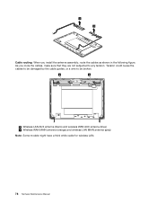
3 3 Cable routing: When you route the cables, make sure that they are not subjected to be damaged by the cable guides, or a wire to any tension. As you install the antenna assembly, route the cables as shown in the following figure. a b a : Wireless LAN AUX antenna (black) and wireless WAN AUX antenna (blue) b : Wireless WAN MAIN antenna (orange) and wireless LAN MAIN antenna (gray) Note: Some models might have a third white cable for wireless LAN. 78 Hardware Maintenance Manual Tension could cause the cables to be broken.
3 3 Cable routing: When you route the cables, make sure that they are not subjected to be damaged by the cable guides, or a wire to any tension. As you install the antenna assembly, route the cables as shown in the following figure. a b a : Wireless LAN AUX antenna (black) and wireless WAN AUX antenna (blue) b : Wireless WAN MAIN antenna (orange) and wireless LAN MAIN antenna (gray) Note: Some models might have a third white cable for wireless LAN. 78 Hardware Maintenance Manual Tension could cause the cables to be broken.
Hardware Maintenance Manual
Page 94
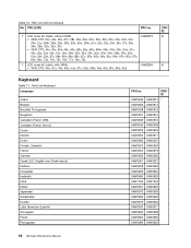
... Table 10. English and Greek layout) Hebrew Hungarian Icelandic India Italian Japanese Kazakhstan Korean Latin American Spanish Norwegian Polish Portuguese FRU no . 7 LCD cover kit, black, without WAN 04W2219 • 3035-CTO, 24x, 25x, 26x, 27x, 28x, 29x, 2Ax, 2Cx, 2Dx, 2Ex, 2Fx, 2Gx, 2Hx, 2Jx, 2Kx, 2Lx, 2Mx, 2Nx, 2Qx..., 68x, 69x, 6Ax, 6Bx, 6Cx, 6Ex, 6Gx, 6Kx, 6Lx, 6Nx, 6Px, 6Qx, 6Tx, 6Vx, 6Xx, 73x, 74x, 75x, 76x, 77x, 78x, 79x 7 LCD cover kit, black, with WAN • 3043-CTO, 49x, 4Cx, 4Fx, 4Gx, 4Jx, 4Tx, 5Qx, 5Wx, 64x, 66x, 6Fx, 6Rx, 6Zx 04W2249 CRU ID N N Keyboard Table 11. Parts...
... Table 10. English and Greek layout) Hebrew Hungarian Icelandic India Italian Japanese Kazakhstan Korean Latin American Spanish Norwegian Polish Portuguese FRU no . 7 LCD cover kit, black, without WAN 04W2219 • 3035-CTO, 24x, 25x, 26x, 27x, 28x, 29x, 2Ax, 2Cx, 2Dx, 2Ex, 2Fx, 2Gx, 2Hx, 2Jx, 2Kx, 2Lx, 2Mx, 2Nx, 2Qx..., 68x, 69x, 6Ax, 6Bx, 6Cx, 6Ex, 6Gx, 6Kx, 6Lx, 6Nx, 6Px, 6Qx, 6Tx, 6Vx, 6Xx, 73x, 74x, 75x, 76x, 77x, 78x, 79x 7 LCD cover kit, black, with WAN • 3043-CTO, 49x, 4Cx, 4Fx, 4Gx, 4Jx, 4Tx, 5Qx, 5Wx, 64x, 66x, 6Fx, 6Rx, 6Zx 04W2249 CRU ID N N Keyboard Table 11. Parts...

Hardware Maintenance Manual
Page 95
... head (20) • M2 × 4 mm (silver), wafer head (10) • M2.5 × 5 mm (black), wafer head (10) • M2 × 8 mm (black), wafer head (5) • M3 × 3.5 mm (black), wafer head (5) • M2 × 5 mm (black), wafer head (15) FRU no . 45N0122 42T4423 42T4419 CRU ID * Table 14. English U.S. Parts list-2-pin ac...
... head (20) • M2 × 4 mm (silver), wafer head (10) • M2.5 × 5 mm (black), wafer head (10) • M2 × 8 mm (black), wafer head (5) • M3 × 3.5 mm (black), wafer head (5) • M2 × 5 mm (black), wafer head (15) FRU no . 45N0122 42T4423 42T4419 CRU ID * Table 14. English U.S. Parts list-2-pin ac...
(English) User Guide
Page 59
... enable the Extend desktop function, do the following : 1. Press F6, then select Extend. Click the Monitor-1 icon (for using the DirectDraw or the Direct3D is blacked out. The Communications settings window opens. 2. Connect the external monitor to an electrical outlet. 2. Using your computer has the Intel display adapter, you are in...
... enable the Extend desktop function, do the following : 1. Press F6, then select Extend. Click the Monitor-1 icon (for using the DirectDraw or the Direct3D is blacked out. The Communications settings window opens. 2. Connect the external monitor to an electrical outlet. 2. Using your computer has the Intel display adapter, you are in...
(English) User Guide
Page 98
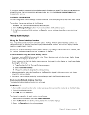
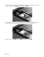
Align the contact edge of the new PCI Express Mini Card with the screw 2 . 8. Pivot the card until you can snap it into place 1 . Be sure to attach the gray cable to the connector marked "MAIN" or "M" on the card, and the black cable to the new PCI Express Mini Card. Put the cover back in place 1 , close the cover 2 , and then tighten the screws 3 . 82 User Guide Connect the cables to the connector marked "AUX" or "A." 9. Secure the card with the corresponding socket. 7.
Align the contact edge of the new PCI Express Mini Card with the screw 2 . 8. Pivot the card until you can snap it into place 1 . Be sure to attach the gray cable to the connector marked "MAIN" or "M" on the card, and the black cable to the new PCI Express Mini Card. Put the cover back in place 1 , close the cover 2 , and then tighten the screws 3 . 82 User Guide Connect the cables to the connector marked "AUX" or "A." 9. Secure the card with the corresponding socket. 7.
