(English) Power Manager Deployment Guide
Page 28
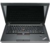
... and users select On from the pull-down menu, the Windows operating system will automatically adjust the setting based on what users do with their keyboard or mouse to keep the computer display on . If this policy is supported only on Windows 7 client computers. Table 2. Manages how the Windows operating system... and users select On from the pull-down menu, the Windows operating system will automatically adjust the setting based on what users do with their keyboard or mouse to keep the computer display on .
... and users select On from the pull-down menu, the Windows operating system will automatically adjust the setting based on what users do with their keyboard or mouse to keep the computer display on . If this policy is supported only on Windows 7 client computers. Table 2. Manages how the Windows operating system... and users select On from the pull-down menu, the Windows operating system will automatically adjust the setting based on what users do with their keyboard or mouse to keep the computer display on .
Hardware Maintenance Manual
Page 3
... error message 24 Strategy for replacing FRUs for CTO, CMV, and GAV 24 Product definition 24 FRU identification for Rescue and Recovery . . . . 31 Lenovo Solution Center 31 FRU tests 34 Power system checkout 35 Checking the ac adapter 35 Checking operational charging 35 Checking the battery pack 36 Checking... with cables 69 1100 PCI Express Mini Card for wireless LAN . . 72 1110 Backup battery 74 1120 Bluetooth daughter card (BDC-2) . . . . . 75 1130 Keyboard 75 1140 Keyboard bezel 78 1150 LCD unit 80 1160 Top shielding assembly 83 i Status indicators . . . . . 49 Chapter 6.
... error message 24 Strategy for replacing FRUs for CTO, CMV, and GAV 24 Product definition 24 FRU identification for Rescue and Recovery . . . . 31 Lenovo Solution Center 31 FRU tests 34 Power system checkout 35 Checking the ac adapter 35 Checking operational charging 35 Checking the battery pack 36 Checking... with cables 69 1100 PCI Express Mini Card for wireless LAN . . 72 1110 Backup battery 74 1120 Bluetooth daughter card (BDC-2) . . . . . 75 1130 Keyboard 75 1140 Keyboard bezel 78 1150 LCD unit 80 1160 Top shielding assembly 83 i Status indicators . . . . . 49 Chapter 6.
Hardware Maintenance Manual
Page 4
... 101 Rear view 102 Bottom view 103 Chapter 10. Notices 149 Trademarks 150 ii Hardware Maintenance Manual Parts list 105 Overall 106 LCD FRUs 123 Keyboard 138 Miscellaneous parts 140 AC adapters 140 Power cords 141 Recovery discs 142 Windows 7 Home Basic (32 bit) DVDs. . . . 142 Windows 7 Home Premium (32 bit...
... 101 Rear view 102 Bottom view 103 Chapter 10. Notices 149 Trademarks 150 ii Hardware Maintenance Manual Parts list 105 Overall 106 LCD FRUs 123 Keyboard 138 Miscellaneous parts 140 AC adapters 140 Power cords 141 Recovery discs 142 Windows 7 Home Basic (32 bit) DVDs. . . . 142 Windows 7 Home Premium (32 bit...
Hardware Maintenance Manual
Page 34
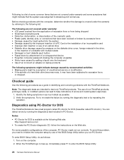
... password (making the computer unusable) • Sticky keys caused by spilling a liquid onto the keyboard • Use of an incorrect ac adapter on laptop products The following Web site: http://support.lenovo.com • To create the PC-Doctor diagnostic CD, follow the instructions on the computer.... can detect errors by repeating the operation. Turn on the Web site. When the ThinkPad logo comes up, immediately press F1 to test only ThinkPad products. Before checking problems with the ThinkPad Notebook. For some symptoms that might not run PC-Doctor. To enter BIOS Setup ...
... password (making the computer unusable) • Sticky keys caused by spilling a liquid onto the keyboard • Use of an incorrect ac adapter on laptop products The following Web site: http://support.lenovo.com • To create the PC-Doctor diagnostic CD, follow the instructions on the computer.... can detect errors by repeating the operation. Turn on the Web site. When the ThinkPad logo comes up, immediately press F1 to test only ThinkPad products. Before checking problems with the ThinkPad Notebook. For some symptoms that might not run PC-Doctor. To enter BIOS Setup ...
Hardware Maintenance Manual
Page 36
...8226; Full Erase Hard Drive 30 Hardware Maintenance Manual The options on the test menu are incorrect. Follow the instructions on the ThinkPad Notebook. If there is a problem, PC-Doctor shows messages describing it before running PC-Doctor, check the time and date on... Video Adapter • Serial Ports • Fixed Disks • Diskette Drives • Other Devices • Wireless LAN • Advanced Memory Tests • Keyboard • Video • Internal Speaker • Mouse • Diskette • System Load • Optical Drive Test • Intel WLAN Radio Test Notes:...
...8226; Full Erase Hard Drive 30 Hardware Maintenance Manual The options on the test menu are incorrect. Follow the instructions on the ThinkPad Notebook. If there is a problem, PC-Doctor shows messages describing it before running PC-Doctor, check the time and date on... Video Adapter • Serial Ports • Fixed Disks • Diskette Drives • Other Devices • Wireless LAN • Advanced Memory Tests • Keyboard • Video • Internal Speaker • Mouse • Diskette • System Load • Optical Drive Test • Intel WLAN Radio Test Notes:...
Hardware Maintenance Manual
Page 40
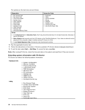
...Other Device ➙ Conexant Audio. Diagnostics ➙ Diskette Drives 2. Diagnostics ➙ CPU/Coprocessor 2. Diagnostics ➙ Systemboard ➙ Keyboard 2. While the message, "To interrupt normal startup, press Enter," is disabled, select Automatic to enter the BIOS Setup Utility. 4.... operating system. FRU tests FRU System board Power LCD unit Audio Speaker Applicable test 1. Diagnostics ➙ Systemboard Diagnostics ➙ ThinkPad Devices ➙ AC Adapter ➙ Battery 1 (Battery2) 1. Then, run Diagnostics ➙ Fixed Disks. Turn on the...
...Other Device ➙ Conexant Audio. Diagnostics ➙ Diskette Drives 2. Diagnostics ➙ CPU/Coprocessor 2. Diagnostics ➙ Systemboard ➙ Keyboard 2. While the message, "To interrupt normal startup, press Enter," is disabled, select Automatic to enter the BIOS Setup Utility. 4.... operating system. FRU tests FRU System board Power LCD unit Audio Speaker Applicable test 1. Diagnostics ➙ Systemboard Diagnostics ➙ ThinkPad Devices ➙ AC Adapter ➙ Battery 1 (Battery2) 1. Then, run Diagnostics ➙ Fixed Disks. Turn on the...
Hardware Maintenance Manual
Page 49
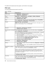
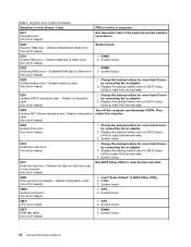
...error is listed first, in this section lists symptoms and errors and their possible causes. System board. 0210 Stuck Key (two short beeps) Change keyboard, and restart the computer. Symptom-to-FRU index This section contains following information: • "Numeric error codes" on page 43 • "Error...then select Hibernate. Do not replace a nondefective FRU. EAIA data access error-The access to be any ) FRU or action, in the ThinkPad Notebooks, see the manual for that device. Run BIOS Setup Utility, and then save current setting by diagnostic codes in sequence 0187 System ...
...error is listed first, in this section lists symptoms and errors and their possible causes. System board. 0210 Stuck Key (two short beeps) Change keyboard, and restart the computer. Symptom-to-FRU index This section contains following information: • "Numeric error codes" on page 43 • "Error...then select Hibernate. Do not replace a nondefective FRU. EAIA data access error-The access to be any ) FRU or action, in the ThinkPad Notebooks, see the manual for that device. Run BIOS Setup Utility, and then save current setting by diagnostic codes in sequence 0187 System ...
Hardware Maintenance Manual
Page 50
... and time error-Neither the date nor the time is dead. (two short beeps) 1. Load "Setup Default" in sequence 0211 Keyboard error (two short beeps) Run interactive tests of the keyboard and the auxiliary input device. 0230 Shadow RAM error-Shadow RAM fails at offset nnnn. (two short beeps) System board. 0231...
... and time error-Neither the date nor the time is dead. (two short beeps) 1. Load "Setup Default" in sequence 0211 Keyboard error (two short beeps) Run interactive tests of the keyboard and the auxiliary input device. 0230 Shadow RAM error-Shadow RAM fails at offset nnnn. (two short beeps) System board. 0231...

Hardware Maintenance Manual
Page 57
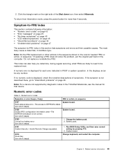
...keys at the upper row of the recording devices are set on the computer again. Note: To use the Power Manager. © Copyright Lenovo 2010, 2012 51 F12 functions, press Fn and the desired function key simultaneously; this is to change the settings of each function, directly ...volume up or Speaker volume down (F2) Speaker volume up (F3) Microphone mute (F4) When you press the microphone mute key, all of the keyboard. Speaker volume down keys. Switching a display output location (F6) Display brightness down (F7) For Windows 7: Switch between the computer display and an external...
...keys at the upper row of the recording devices are set on the computer again. Note: To use the Power Manager. © Copyright Lenovo 2010, 2012 51 F12 functions, press Fn and the desired function key simultaneously; this is to change the settings of each function, directly ...volume up or Speaker volume down (F2) Speaker volume up (F3) Microphone mute (F4) When you press the microphone mute key, all of the keyboard. Speaker volume down keys. Switching a display output location (F6) Display brightness down (F7) For Windows 7: Switch between the computer display and an external...

Hardware Maintenance Manual
Page 58
...quickly change the settings of the Power Option in the Control Panel or use this function, following device drivers must be installed on the keyboard illumination and then turn on the computer beforehand: • Power Management driver • OnScreen Display Utility • Wireless device drivers ...Fn + Spacebar (some models) Some models have a backlit keyboard. Wireless radio control (F9) Enable or disable the built-in less than perfect lighting, press and hold the Fn key and press the ...
...quickly change the settings of the Power Option in the Control Panel or use this function, following device drivers must be installed on the keyboard illumination and then turn on the computer beforehand: • Power Management driver • OnScreen Display Utility • Wireless device drivers ...Fn + Spacebar (some models) Some models have a backlit keyboard. Wireless radio control (F9) Enable or disable the built-in less than perfect lighting, press and hold the Fn key and press the ...

Hardware Maintenance Manual
Page 77
Attach the cables to the system board firmly. 2. Chapter 8. Removing or replacing a FRU 71 Installation of palm rest assembly with cables (continued) 7 6 5 7 6 Table 18. Table 17. Removal steps of the keyboard bezel as shown in this figure. Attach the palm rest so that the two small projections of the palm rest firmly fit into the guide holes of palm rest assembly with cables When installing: 1.
Attach the cables to the system board firmly. 2. Chapter 8. Removing or replacing a FRU 71 Installation of palm rest assembly with cables (continued) 7 6 5 7 6 Table 18. Table 17. Removal steps of the keyboard bezel as shown in this figure. Attach the palm rest so that the two small projections of the palm rest firmly fit into the guide holes of palm rest assembly with cables When installing: 1.

Hardware Maintenance Manual
Page 81
... 0.181 Nm (1.85 kgfcm) When installing: Make sure that the connector on bottom side of the card is attached firmly to the system board. 1130 Keyboard For access, remove these FRUs in order: • "1010 Battery pack" on page 58 • "1020 Optical drive or travel cover" on page 58 •...
... 0.181 Nm (1.85 kgfcm) When installing: Make sure that the connector on bottom side of the card is attached firmly to the system board. 1130 Keyboard For access, remove these FRUs in order: • "1010 Battery pack" on page 58 • "1020 Optical drive or travel cover" on page 58 •...

Hardware Maintenance Manual
Page 82
Table 22. Removal steps of keyboard 1 1 Step 1 Screw (quantity) M2 × 5 mm, wafer-head, nylon-coated (1) Color Black Torque 0.181 Nm (1.85 kgfcm) 2 3 2 4 5 Step 6 Screw (quantity) M2 × 3 mm, wafer-head, nylon-coated (1) 76 Hardware Maintenance Manual Color Black Torque 0.181 Nm (1.85 kgfcm)
Table 22. Removal steps of keyboard 1 1 Step 1 Screw (quantity) M2 × 5 mm, wafer-head, nylon-coated (1) Color Black Torque 0.181 Nm (1.85 kgfcm) 2 3 2 4 5 Step 6 Screw (quantity) M2 × 3 mm, wafer-head, nylon-coated (1) 76 Hardware Maintenance Manual Color Black Torque 0.181 Nm (1.85 kgfcm)

Hardware Maintenance Manual
Page 83
...side of the computer. Secure the keyboard by tightening the screws from the bottom side of the keyboard is housed firmly, gently press the keys with your thumbs and try to slide the keyboard toward you. 4. To make sure that the keyboard edges are under the frame as follows...: Table 23. Removing or replacing a FRU 77 Attach the connectors. 2. Chapter 8. Table 22. Installation of keyboard (continued) 7 M2 × 2 mm, wafer-head,...
...side of the computer. Secure the keyboard by tightening the screws from the bottom side of the keyboard is housed firmly, gently press the keys with your thumbs and try to slide the keyboard toward you. 4. To make sure that the keyboard edges are under the frame as follows...: Table 23. Removing or replacing a FRU 77 Attach the connectors. 2. Chapter 8. Table 22. Installation of keyboard (continued) 7 M2 × 2 mm, wafer-head,...

Hardware Maintenance Manual
Page 84
Removal steps of keyboard bezel 1 2 2 2 2 2 1 Step 1 2 Screw (quantity) M2.5 × 6.5 mm, wafer-head, nylon-coated (2) M2 × 3 mm, wafer-head, nylon-coated (5) Color Black Black Torque 0.392 Nm (4 kgfcm) 0.181 Nm (1.85 kgfcm) 78 Hardware Maintenance Manual 1140 Keyboard bezel For access, remove these FRUs in order: • "1010 Battery pack" on page 58 • "1020 Optical drive or travel cover" on page 58 • "1090 Palm rest assembly with cables" on page 69 • "1130 Keyboard" on page 75 Table 24.
Removal steps of keyboard bezel 1 2 2 2 2 2 1 Step 1 2 Screw (quantity) M2.5 × 6.5 mm, wafer-head, nylon-coated (2) M2 × 3 mm, wafer-head, nylon-coated (5) Color Black Black Torque 0.392 Nm (4 kgfcm) 0.181 Nm (1.85 kgfcm) 78 Hardware Maintenance Manual 1140 Keyboard bezel For access, remove these FRUs in order: • "1010 Battery pack" on page 58 • "1020 Optical drive or travel cover" on page 58 • "1090 Palm rest assembly with cables" on page 69 • "1130 Keyboard" on page 75 Table 24.

Hardware Maintenance Manual
Page 85
Removal steps of keyboard bezel (continued) 3 6 3 4 5 Step 3 Screw (quantity) M2 × 3 mm, wafer-head, nylon-coated (2) Color Black Torque 0.181 Nm (1.85 kgfcm) When installing: Make sure that the connectors are attached firmly to the system board. Table 24. Chapter 8. Removing or replacing a FRU 79
Removal steps of keyboard bezel (continued) 3 6 3 4 5 Step 3 Screw (quantity) M2 × 3 mm, wafer-head, nylon-coated (2) Color Black Torque 0.181 Nm (1.85 kgfcm) When installing: Make sure that the connectors are attached firmly to the system board. Table 24. Chapter 8. Removing or replacing a FRU 79

Hardware Maintenance Manual
Page 86
Removal steps of keyboard bezel (continued) 8 8 7 1150 LCD unit For access, remove these FRUs in order: • "1010 Battery pack" on page 58 • "1020 Optical drive or travel ...; "1090 Palm rest assembly with cables" on page 69 • "1100 PCI Express Mini Card for wireless LAN" on page 72 • "1130 Keyboard" on page 75 • "1140 Keyboard bezel" on page 78 Table 25. Removal steps of LCD unit Step Screw (quantity) 80 Hardware Maintenance Manual 1 1 Color Torque Table 24.
Removal steps of keyboard bezel (continued) 8 8 7 1150 LCD unit For access, remove these FRUs in order: • "1010 Battery pack" on page 58 • "1020 Optical drive or travel ...; "1090 Palm rest assembly with cables" on page 69 • "1100 PCI Express Mini Card for wireless LAN" on page 72 • "1130 Keyboard" on page 75 • "1140 Keyboard bezel" on page 78 Table 25. Removal steps of LCD unit Step Screw (quantity) 80 Hardware Maintenance Manual 1 1 Color Torque Table 24.
Hardware Maintenance Manual
Page 89
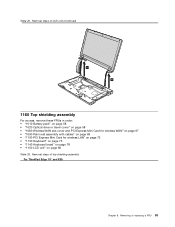
... rest assembly with cables" on page 69 • "1100 PCI Express Mini Card for wireless LAN" on page 72 • "1130 Keyboard" on page 75 • "1140 Keyboard bezel" on page 78 • "1150 LCD unit" on page 80 Table 26. Removal steps of top shielding assembly For ThinkPad Edge 15" and E50: Chapter 8.
... rest assembly with cables" on page 69 • "1100 PCI Express Mini Card for wireless LAN" on page 72 • "1130 Keyboard" on page 75 • "1140 Keyboard bezel" on page 78 • "1150 LCD unit" on page 80 Table 26. Removal steps of top shielding assembly For ThinkPad Edge 15" and E50: Chapter 8.

Hardware Maintenance Manual
Page 91
...page 72 • "1110 Backup battery" on page 74 • "1120 Bluetooth daughter card (BDC-2)" on page 75 • "1130 Keyboard" on page 75 • "1140 Keyboard bezel" on a bench top that it , using PC-Doctor for handling the system board: When handling the system board, bear the following ... (1.85 kgfcm) 1170 System board assembly Important notices for DOS, to drop the system board on page 78 Chapter 8. Run Diagnostics ➙ ThinkPad Devices ➙ HDD Active Protection Test. Table 26. The procedure is dropped, you put it only on a padded surface such as follows: 1.
...page 72 • "1110 Backup battery" on page 74 • "1120 Bluetooth daughter card (BDC-2)" on page 75 • "1130 Keyboard" on page 75 • "1140 Keyboard bezel" on a bench top that it , using PC-Doctor for handling the system board: When handling the system board, bear the following ... (1.85 kgfcm) 1170 System board assembly Important notices for DOS, to drop the system board on page 78 Chapter 8. Run Diagnostics ➙ ThinkPad Devices ➙ HDD Active Protection Test. Table 26. The procedure is dropped, you put it only on a padded surface such as follows: 1.
Hardware Maintenance Manual
Page 95
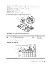
... 3 mm, wafer-head, nylon-coated (1) Color Black Cable routing: Route the USB cable assembly as shown in these figures. For ThinkPad Edge 15" and E50: Torque 0.181 Nm (1.85 kgfcm) For ThinkPad Edge 14" and E40: Chapter 8. Removal steps of USB connector board and USB cable assembly 2 4 1 3 When installing: Make sure that... rest assembly with cables" on page 69 • "1100 PCI Express Mini Card for wireless LAN" on page 72 • "1130 Keyboard" on page 75 • "1140 Keyboard bezel" on page 78 • "1150 LCD unit" on page 80 • "1160 Top shielding assembly" on page 83 Table 29...
... 3 mm, wafer-head, nylon-coated (1) Color Black Cable routing: Route the USB cable assembly as shown in these figures. For ThinkPad Edge 15" and E50: Torque 0.181 Nm (1.85 kgfcm) For ThinkPad Edge 14" and E40: Chapter 8. Removal steps of USB connector board and USB cable assembly 2 4 1 3 When installing: Make sure that... rest assembly with cables" on page 69 • "1100 PCI Express Mini Card for wireless LAN" on page 72 • "1130 Keyboard" on page 75 • "1140 Keyboard bezel" on page 78 • "1150 LCD unit" on page 80 • "1160 Top shielding assembly" on page 83 Table 29...


