
Harware Maintenance Manual
Page 3
...23 Checkout guide 24 Diagnostics using Recovery Disc Set 33 Passwords 34 Power-on password 34 Hard-disk password 34 Supervisor password 35 © Copyright Lenovo 2009, 2012 How to remove the power-on password . . . 35 How to remove the hard-disk password . . . 35 Power management... programs 28 Lenovo ThinkVantage Toolbox 29 FRU tests 29 Power system checkout 30 Checking the AC adapter 30 Checking operational charging 31 Checking the battery pack 31 Checking the backup battery 32 Chapter 4. Removing and replacing a FRU 51 1010 Battery pack 52 1020 Bottom slot cover 52 1030...
...23 Checkout guide 24 Diagnostics using Recovery Disc Set 33 Passwords 34 Power-on password 34 Hard-disk password 34 Supervisor password 35 © Copyright Lenovo 2009, 2012 How to remove the power-on password . . . 35 How to remove the hard-disk password . . . 35 Power management... programs 28 Lenovo ThinkVantage Toolbox 29 FRU tests 29 Power system checkout 30 Checking the AC adapter 30 Checking operational charging 31 Checking the battery pack 31 Checking the backup battery 32 Chapter 4. Removing and replacing a FRU 51 1010 Battery pack 52 1020 Bottom slot cover 52 1030...

Harware Maintenance Manual
Page 58
... list for replacing a battery pack: ThinkVantage Toolbox has an automatic battery diagnostic that determines if the battery pack is in the locked position. 1020 Bottom slot cover For access, remove this FRU: • "1010 Battery pack" on page 52 52 Hardware Maintenance Manual Unlock the battery latch 1 . A battery pack ... in the unlocked position 2 , remove the battery pack in the direction shown by arrow 3 . 1 2 3 When installing: Install the battery pack in the slot, and then make sure that the battery latch is defective. 1010 Battery pack Important notice for your computer.
... list for replacing a battery pack: ThinkVantage Toolbox has an automatic battery diagnostic that determines if the battery pack is in the locked position. 1020 Bottom slot cover For access, remove this FRU: • "1010 Battery pack" on page 52 52 Hardware Maintenance Manual Unlock the battery latch 1 . A battery pack ... in the unlocked position 2 , remove the battery pack in the direction shown by arrow 3 . 1 2 3 When installing: Install the battery pack in the slot, and then make sure that the battery latch is defective. 1010 Battery pack Important notice for your computer.

Harware Maintenance Manual
Page 59
Applying label to the bottom slot cover When you replace the cover, following figure: Chapter 8. Then secure the screws. Removing and replacing a FRU 53 Removal steps of bottom slot cover Note: Loosen the screws 1 , but do not remove them. 1 1 1 2 1 1 When installing: Make sure that all the projections of the cover are attached firmly to the following label needs to be peeled off from the old cover, and needs to be put on the new cover: 1 Asset tag label For the label location, refer to the frame.
Applying label to the bottom slot cover When you replace the cover, following figure: Chapter 8. Then secure the screws. Removing and replacing a FRU 53 Removal steps of bottom slot cover Note: Loosen the screws 1 , but do not remove them. 1 1 1 2 1 1 When installing: Make sure that all the projections of the cover are attached firmly to the following label needs to be peeled off from the old cover, and needs to be put on the new cover: 1 Asset tag label For the label location, refer to the frame.

Harware Maintenance Manual
Page 60
Press the DIMM firmly, and pivot it until it is used on the computer you are servicing, the card must be installed in SLOT-0 ( a ), but not in the slot and does not move easily. 54 Hardware Maintenance Manual 1 1030 DIMM For access, remove these FRUs in order: • "1010 Battery pack" on page 52 • "1020 Bottom slot cover" on page 52 Removal steps of the DIMM into the place. When installing: Insert the notched end of DIMM 1 2 1 a b Note: If only one DIMM is firmly fixed in SLOT-1 ( b ). Make sure that it snaps into the socket.
Press the DIMM firmly, and pivot it until it is used on the computer you are servicing, the card must be installed in SLOT-0 ( a ), but not in the slot and does not move easily. 54 Hardware Maintenance Manual 1 1030 DIMM For access, remove these FRUs in order: • "1010 Battery pack" on page 52 • "1020 Bottom slot cover" on page 52 Removal steps of the DIMM into the place. When installing: Insert the notched end of DIMM 1 2 1 a b Note: If only one DIMM is firmly fixed in SLOT-1 ( b ). Make sure that it snaps into the socket.

Harware Maintenance Manual
Page 61
... possible. • Never remove the drive while the system is operating or is in order: • "1010 Battery pack" on page 52 • "1020 Bottom slot cover" on it . Removing and replacing a FRU 55 1040 Hard disk drive (HDD) For access, remove these FRUs in suspend mode. Improper handling can cause damage...
... possible. • Never remove the drive while the system is operating or is in order: • "1010 Battery pack" on page 52 • "1020 Bottom slot cover" on it . Removing and replacing a FRU 55 1040 Hard disk drive (HDD) For access, remove these FRUs in suspend mode. Improper handling can cause damage...

Harware Maintenance Manual
Page 62
3 When installing: Make sure that the HDD connector is attached firmly. 1050 PCI Express Mini Card for wireless LAN For access, remove these FRUs in order: • "1010 Battery pack" on page 52 • "1020 Bottom slot cover" on page 52 Removal steps of PCI Express Mini Card for wireless LAN In step 1 , unplug the jacks by using the removal tool antenna RF connector (P/N: 08K7159) or pick the connectors with your fingers and gently unplug them in direction of the arrow. 56 Hardware Maintenance Manual
3 When installing: Make sure that the HDD connector is attached firmly. 1050 PCI Express Mini Card for wireless LAN For access, remove these FRUs in order: • "1010 Battery pack" on page 52 • "1020 Bottom slot cover" on page 52 Removal steps of PCI Express Mini Card for wireless LAN In step 1 , unplug the jacks by using the removal tool antenna RF connector (P/N: 08K7159) or pick the connectors with your fingers and gently unplug them in direction of the arrow. 56 Hardware Maintenance Manual

Harware Maintenance Manual
Page 64
• "1010 Battery pack" on page 52 • "1020 Bottom slot cover" on page 52 Removal steps of PCI Express Mini Card for wireless WAN In step 1 , unplug the jacks by using the removal tool antenna RF connector (P/N: 08K7159) or pick the connectors with your fingers and gently unplug them in direction of the arrow. 2 2 1 Step 2 Screw (quantity) M2 × 3 mm, flat-head, nylon-coated (2) 3 Color Black Torque 0.181 Nm (1.85 kgfcm) 58 Hardware Maintenance Manual
• "1010 Battery pack" on page 52 • "1020 Bottom slot cover" on page 52 Removal steps of PCI Express Mini Card for wireless WAN In step 1 , unplug the jacks by using the removal tool antenna RF connector (P/N: 08K7159) or pick the connectors with your fingers and gently unplug them in direction of the arrow. 2 2 1 Step 2 Screw (quantity) M2 × 3 mm, flat-head, nylon-coated (2) 3 Color Black Torque 0.181 Nm (1.85 kgfcm) 58 Hardware Maintenance Manual

Harware Maintenance Manual
Page 65
Removing and replacing a FRU 59 When installing: Plug the red cable into the jack marked MAIN, and the blue cable into the jack marked AUX on the card. 1070 Keyboard For access, remove these FRUs in order: • "1010 Battery pack" on page 52 • "1020 Bottom slot cover" on page 52 Removal steps of keyboard 1 1 Step 1 Screw (quantity) M2 × 5 mm, flat-head, nylon-coated (2) Color Black Torque 0.181 Nm (1.85 kgfcm) In step 2 , by using a plastic pry tool, push the keyboard out from two square holes in the battery pack slot as shown in this figure. 2 Chapter 8.
Removing and replacing a FRU 59 When installing: Plug the red cable into the jack marked MAIN, and the blue cable into the jack marked AUX on the card. 1070 Keyboard For access, remove these FRUs in order: • "1010 Battery pack" on page 52 • "1020 Bottom slot cover" on page 52 Removal steps of keyboard 1 1 Step 1 Screw (quantity) M2 × 5 mm, flat-head, nylon-coated (2) Color Black Torque 0.181 Nm (1.85 kgfcm) In step 2 , by using a plastic pry tool, push the keyboard out from two square holes in the battery pack slot as shown in this figure. 2 Chapter 8.

Harware Maintenance Manual
Page 67
... computer. 1080 Top case assembly and microphone module For access, remove these FRUs in order: • "1010 Battery pack" on page 52 • "1020 Bottom slot cover" on page 52 • "1040 Hard disk drive (HDD)" on page 55 • "1070 Keyboard" on page 59 Note: Microphone module is attached on the...
... computer. 1080 Top case assembly and microphone module For access, remove these FRUs in order: • "1010 Battery pack" on page 52 • "1020 Bottom slot cover" on page 52 • "1040 Hard disk drive (HDD)" on page 55 • "1070 Keyboard" on page 59 Note: Microphone module is attached on the...

Harware Maintenance Manual
Page 70
9 9 9 9 9 10 9 9 9 9 9 12 12 13 14 11 1090 Backup battery For access, remove these FRUs in order: • "1010 Battery pack" on page 52 • "1020 Bottom slot cover" on page 52 • "1070 Keyboard" on page 59 • "1080 Top case assembly and microphone module" on page 61 64 Hardware Maintenance Manual
9 9 9 9 9 10 9 9 9 9 9 12 12 13 14 11 1090 Backup battery For access, remove these FRUs in order: • "1010 Battery pack" on page 52 • "1020 Bottom slot cover" on page 52 • "1070 Keyboard" on page 59 • "1080 Top case assembly and microphone module" on page 61 64 Hardware Maintenance Manual

Harware Maintenance Manual
Page 71
Any other battery could ignite or explode. 1 2 When installing: Make sure that the connector is attached firmly. 1100 Bluetooth daughter card (BDC-2) For access, remove these FRUs in the parts list for your computer. Removing and replacing a FRU 65 Removal steps of backup battery DANGER Use only the battery specified in order: • "1010 Battery pack" on page 52 • "1020 Bottom slot cover" on page 52 • "1070 Keyboard" on page 59 • "1080 Top case assembly and microphone module" on page 61 Chapter 8.
Any other battery could ignite or explode. 1 2 When installing: Make sure that the connector is attached firmly. 1100 Bluetooth daughter card (BDC-2) For access, remove these FRUs in the parts list for your computer. Removing and replacing a FRU 65 Removal steps of backup battery DANGER Use only the battery specified in order: • "1010 Battery pack" on page 52 • "1020 Bottom slot cover" on page 52 • "1070 Keyboard" on page 59 • "1080 Top case assembly and microphone module" on page 61 Chapter 8.

Harware Maintenance Manual
Page 72
Removal steps of BDC-2 1 2 Step 1 Screw (quantity) M2 × 3 mm, flat-head, nylon-coated (1) Color Black When installing: Make sure that the connector is attached firmly. 1110 Speaker assembly For access, remove these FRUs in order: • "1010 Battery pack" on page 52 • "1020 Bottom slot cover" on page 52 • "1070 Keyboard" on page 59 • "1080 Top case assembly and microphone module" on page 61 Torque 0.181 Nm (1.85 kgfcm) 66 Hardware Maintenance Manual
Removal steps of BDC-2 1 2 Step 1 Screw (quantity) M2 × 3 mm, flat-head, nylon-coated (1) Color Black When installing: Make sure that the connector is attached firmly. 1110 Speaker assembly For access, remove these FRUs in order: • "1010 Battery pack" on page 52 • "1020 Bottom slot cover" on page 52 • "1070 Keyboard" on page 59 • "1080 Top case assembly and microphone module" on page 61 Torque 0.181 Nm (1.85 kgfcm) 66 Hardware Maintenance Manual

Harware Maintenance Manual
Page 74
For access, remove these FRUs in order: • "1010 Battery pack" on page 52 • "1020 Bottom slot cover" on page 52 • "1030 DIMM" on page 54 • "1040 Hard disk drive (HDD)" on page 55 • "1050 PCI Express Mini Card for ...
For access, remove these FRUs in order: • "1010 Battery pack" on page 52 • "1020 Bottom slot cover" on page 52 • "1030 DIMM" on page 54 • "1040 Hard disk drive (HDD)" on page 55 • "1050 PCI Express Mini Card for ...

Harware Maintenance Manual
Page 81
... firmly. 1130 I/O card assembly, audio cable, and I/O cable For access, remove these FRUs in order: • "1010 Battery pack" on page 52 • "1020 Bottom slot cover" on page 52 • "1040 Hard disk drive (HDD)" on page 55 • "1050 PCI Express Mini Card for wireless LAN" on page 56 •...
... firmly. 1130 I/O card assembly, audio cable, and I/O cable For access, remove these FRUs in order: • "1010 Battery pack" on page 52 • "1020 Bottom slot cover" on page 52 • "1040 Hard disk drive (HDD)" on page 55 • "1050 PCI Express Mini Card for wireless LAN" on page 56 •...

Harware Maintenance Manual
Page 83
... as shown in this figure. 1140 LCD unit For access, remove these FRUs in order: • "1010 Battery pack" on page 52 • "1020 Bottom slot cover" on page 52 • "1040 Hard disk drive (HDD)" on page 55 • "1050 PCI Express Mini Card for wireless LAN" on page 56 •...
... as shown in this figure. 1140 LCD unit For access, remove these FRUs in order: • "1010 Battery pack" on page 52 • "1020 Bottom slot cover" on page 52 • "1040 Hard disk drive (HDD)" on page 55 • "1050 PCI Express Mini Card for wireless LAN" on page 56 •...
Harware Maintenance Manual
Page 86
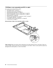
... and DC-in cable For access, remove these FRUs in order: • "1010 Battery pack" on page 52 • "1020 Bottom slot cover" on page 52 • "1040 Hard disk drive (HDD)" on page 55 • "1050 PCI Express Mini Card for wireless LAN" on page 56 • "... assembly" on page 66 • "1120 System board and fan assembly" on page 68 • "1140 LCD unit" on page 77 Removal steps of base cover assembly and DC-in this figure.
... and DC-in cable For access, remove these FRUs in order: • "1010 Battery pack" on page 52 • "1020 Bottom slot cover" on page 52 • "1040 Hard disk drive (HDD)" on page 55 • "1050 PCI Express Mini Card for wireless LAN" on page 56 • "... assembly" on page 66 • "1120 System board and fan assembly" on page 68 • "1140 LCD unit" on page 77 Removal steps of base cover assembly and DC-in this figure.

Harware Maintenance Manual
Page 90
2030 LCD panel and LCD cable For access, remove these FRUs in order: • "1010 Battery pack" on page 52 • "1020 Bottom slot cover" on page 52 • "1040 Hard disk drive (HDD)" on page 55 • "1050 PCI Express Mini Card for wireless LAN" on page 56 • "...
2030 LCD panel and LCD cable For access, remove these FRUs in order: • "1010 Battery pack" on page 52 • "1020 Bottom slot cover" on page 52 • "1040 Hard disk drive (HDD)" on page 55 • "1050 PCI Express Mini Card for wireless LAN" on page 56 • "...

Harware Maintenance Manual
Page 92
10 2040 Hinge kit For access, remove these FRUs in order: • "1010 Battery pack" on page 52 • "1020 Bottom slot cover" on page 52 • "1040 Hard disk drive (HDD)" on page 55 • "1050 PCI Express Mini Card for wireless LAN" on page 56 • "...
10 2040 Hinge kit For access, remove these FRUs in order: • "1010 Battery pack" on page 52 • "1020 Bottom slot cover" on page 52 • "1040 Hard disk drive (HDD)" on page 55 • "1050 PCI Express Mini Card for wireless LAN" on page 56 • "...

Harware Maintenance Manual
Page 94
• "1020 Bottom slot cover" on page 52 • "1040 Hard disk drive (HDD)" on page 55 • "1050 PCI Express Mini Card for wireless LAN" on page 56 • "... cable" on page 84 • "2040 Hinge kit" on page 86 Removal steps of wireless LAN antenna assembly, wireless WAN antenna assembly, and LCD rear cover assembly 1 2 2 2 2 1 1 1 3 3 3 3 3 3 88 Hardware Maintenance Manual
• "1020 Bottom slot cover" on page 52 • "1040 Hard disk drive (HDD)" on page 55 • "1050 PCI Express Mini Card for wireless LAN" on page 56 • "... cable" on page 84 • "2040 Hinge kit" on page 86 Removal steps of wireless LAN antenna assembly, wireless WAN antenna assembly, and LCD rear cover assembly 1 2 2 2 2 1 1 1 3 3 3 3 3 3 88 Hardware Maintenance Manual

Harware Maintenance Manual
Page 104
Table 8. CRU ID 11 Base cover assembly for 0196 60Y5528 No 11 Base cover assembly for 0197 60Y5530 No 11 Base cover assembly for 0492 60Y5529 No 11 Base cover assembly for 0217, 0221, and 0250 04W0349 No 12 HDD cover bracket 60Y5532 No 13 HDD slot cover 60Y5517 No 14 SATA hard disk drive, 160 GB, 5,400 rpm...
Table 8. CRU ID 11 Base cover assembly for 0196 60Y5528 No 11 Base cover assembly for 0197 60Y5530 No 11 Base cover assembly for 0492 60Y5529 No 11 Base cover assembly for 0217, 0221, and 0250 04W0349 No 12 HDD cover bracket 60Y5532 No 13 HDD slot cover 60Y5517 No 14 SATA hard disk drive, 160 GB, 5,400 rpm...


