
Harware Maintenance Manual
Page 3
... Disc Set 33 Passwords 34 Power-on password 34 Hard-disk password 34 Supervisor password 35 © Copyright Lenovo 2009, 2012 How to remove the power-on password . . . 35 How to remove the hard-disk password . . . 35 Power management 36 Screen blank mode 36 Sleep mode 36 Hibernation ... use error message 20 Strategy for replacing FRUs for CTO, CMV, and GAV 20 Product definition 20 FRU identification for wireless WAN . . 57 1070 Keyboard 59 1080 Top case assembly and microphone module 61 1090 Backup battery 64 1100 Bluetooth daughter card (BDC-2) . . . . . 65 1110 Speaker ...
... Disc Set 33 Passwords 34 Power-on password 34 Hard-disk password 34 Supervisor password 35 © Copyright Lenovo 2009, 2012 How to remove the power-on password . . . 35 How to remove the hard-disk password . . . 35 Power management 36 Screen blank mode 36 Sleep mode 36 Hibernation ... use error message 20 Strategy for replacing FRUs for CTO, CMV, and GAV 20 Product definition 20 FRU identification for wireless WAN . . 57 1070 Keyboard 59 1080 Top case assembly and microphone module 61 1090 Backup battery 64 1100 Bluetooth daughter card (BDC-2) . . . . . 65 1110 Speaker ...

Harware Maintenance Manual
Page 35
... Turn on the Web site. Diskette drive 1. Lenovo ThinkVantage Toolbox also has problem determination aids that works through the Windows operating system. Table 1. Diagnostics ➙ Video Adapter 2. Diagnostics ➙ Systemboard ➙ Keyboard 2. Remove any diskette from the BIOS Setup Utility, do ... Control Panel ➙ System and Security ➙ Lenovo's System Health and Diagnostics Follow the instructions on the computer. Using cursor keys, select HDD diagnostic program. Interactive Tests ➙ Keyboard Hard disk drive or solid state Enter the BIOS Setup...
... Turn on the Web site. Diskette drive 1. Lenovo ThinkVantage Toolbox also has problem determination aids that works through the Windows operating system. Table 1. Diagnostics ➙ Video Adapter 2. Diagnostics ➙ Systemboard ➙ Keyboard 2. Remove any diskette from the BIOS Setup Utility, do ... Control Panel ➙ System and Security ➙ Lenovo's System Health and Diagnostics Follow the instructions on the computer. Using cursor keys, select HDD diagnostic program. Interactive Tests ➙ Keyboard Hard disk drive or solid state Enter the BIOS Setup...

Harware Maintenance Manual
Page 65
Removing and replacing a FRU 59 When installing: Plug the red cable into the jack marked MAIN, and the blue cable into the jack marked AUX on the card. 1070 Keyboard For access, remove these FRUs in order: • "1010 Battery pack" on page 52 • "1020 Bottom slot cover" on page 52 Removal steps of keyboard 1 1 Step 1 Screw (quantity) M2 × 5 mm, flat-head, nylon-coated (2) Color Black Torque 0.181 Nm (1.85 kgfcm) In step 2 , by using a plastic pry tool, push the keyboard out from two square holes in the battery pack slot as shown in this figure. 2 Chapter 8.
Removing and replacing a FRU 59 When installing: Plug the red cable into the jack marked MAIN, and the blue cable into the jack marked AUX on the card. 1070 Keyboard For access, remove these FRUs in order: • "1010 Battery pack" on page 52 • "1020 Bottom slot cover" on page 52 Removal steps of keyboard 1 1 Step 1 Screw (quantity) M2 × 5 mm, flat-head, nylon-coated (2) Color Black Torque 0.181 Nm (1.85 kgfcm) In step 2 , by using a plastic pry tool, push the keyboard out from two square holes in the battery pack slot as shown in this figure. 2 Chapter 8.

Harware Maintenance Manual
Page 67
... the top case assembly. Removing and replacing a FRU 61 3. Secure the keyboard by tightening the screws from the bottom side of the computer. 1080 Top case assembly and microphone module For access, remove these FRUs in order: • "1010 Battery pack" on page 52 • "1020 Bottom slot cover" on ...page 52 • "1040 Hard disk drive (HDD)" on page 55 • "1070 Keyboard" on page 59 Note: Microphone module is attached on...
... the top case assembly. Removing and replacing a FRU 61 3. Secure the keyboard by tightening the screws from the bottom side of the computer. 1080 Top case assembly and microphone module For access, remove these FRUs in order: • "1010 Battery pack" on page 52 • "1020 Bottom slot cover" on ...page 52 • "1040 Hard disk drive (HDD)" on page 55 • "1070 Keyboard" on page 59 Note: Microphone module is attached on...

Harware Maintenance Manual
Page 70
9 9 9 9 9 10 9 9 9 9 9 12 12 13 14 11 1090 Backup battery For access, remove these FRUs in order: • "1010 Battery pack" on page 52 • "1020 Bottom slot cover" on page 52 • "1070 Keyboard" on page 59 • "1080 Top case assembly and microphone module" on page 61 64 Hardware Maintenance Manual
9 9 9 9 9 10 9 9 9 9 9 12 12 13 14 11 1090 Backup battery For access, remove these FRUs in order: • "1010 Battery pack" on page 52 • "1020 Bottom slot cover" on page 52 • "1070 Keyboard" on page 59 • "1080 Top case assembly and microphone module" on page 61 64 Hardware Maintenance Manual

Harware Maintenance Manual
Page 71
Removal steps of backup battery DANGER Use only the battery specified in order: • "1010 Battery pack" on page 52 • "1020 Bottom slot cover" on page 52 • "1070 Keyboard" on page 59 • "1080 Top case assembly and microphone module" on page 61 Chapter 8. Removing and replacing a FRU 65 Any other battery could ignite or explode. 1 2 When installing: Make sure that the connector is attached firmly. 1100 Bluetooth daughter card (BDC-2) For access, remove these FRUs in the parts list for your computer.
Removal steps of backup battery DANGER Use only the battery specified in order: • "1010 Battery pack" on page 52 • "1020 Bottom slot cover" on page 52 • "1070 Keyboard" on page 59 • "1080 Top case assembly and microphone module" on page 61 Chapter 8. Removing and replacing a FRU 65 Any other battery could ignite or explode. 1 2 When installing: Make sure that the connector is attached firmly. 1100 Bluetooth daughter card (BDC-2) For access, remove these FRUs in the parts list for your computer.

Harware Maintenance Manual
Page 72
Removal steps of BDC-2 1 2 Step 1 Screw (quantity) M2 × 3 mm, flat-head, nylon-coated (1) Color Black When installing: Make sure that the connector is attached firmly. 1110 Speaker assembly For access, remove these FRUs in order: • "1010 Battery pack" on page 52 • "1020 Bottom slot cover" on page 52 • "1070 Keyboard" on page 59 • "1080 Top case assembly and microphone module" on page 61 Torque 0.181 Nm (1.85 kgfcm) 66 Hardware Maintenance Manual
Removal steps of BDC-2 1 2 Step 1 Screw (quantity) M2 × 3 mm, flat-head, nylon-coated (1) Color Black When installing: Make sure that the connector is attached firmly. 1110 Speaker assembly For access, remove these FRUs in order: • "1010 Battery pack" on page 52 • "1020 Bottom slot cover" on page 52 • "1070 Keyboard" on page 59 • "1080 Top case assembly and microphone module" on page 61 Torque 0.181 Nm (1.85 kgfcm) 66 Hardware Maintenance Manual

Harware Maintenance Manual
Page 74
... "1050 PCI Express Mini Card for wireless LAN" on page 56 • "1060 PCI Express Mini Card for wireless WAN" on page 57 • "1070 Keyboard" on page 59 • "1080 Top case assembly and microphone module" on page 61 • "1090 Backup battery" on page 64 • "1100 Bluetooth... daughter card (BDC-2)" on page 65 • "1110 Speaker assembly" on page 66 Removal steps of system board and fan assembly Following components soldered on the top side of the system board are extremely sensitive. Note: Dropping a system board...
... "1050 PCI Express Mini Card for wireless LAN" on page 56 • "1060 PCI Express Mini Card for wireless WAN" on page 57 • "1070 Keyboard" on page 59 • "1080 Top case assembly and microphone module" on page 61 • "1090 Backup battery" on page 64 • "1100 Bluetooth... daughter card (BDC-2)" on page 65 • "1110 Speaker assembly" on page 66 Removal steps of system board and fan assembly Following components soldered on the top side of the system board are extremely sensitive. Note: Dropping a system board...

Harware Maintenance Manual
Page 81
... MT0217 and MT0250: a For MT0221: a a When installing: Make sure that the fan connector is attached firmly. 1130 I/O card assembly, audio cable, and I/O cable For access, remove these FRUs in order: • "1010 Battery pack" on page 52 • "1020 Bottom slot cover" on page 52 • "1040 Hard disk drive (HDD...; "1050 PCI Express Mini Card for wireless LAN" on page 56 • "1060 PCI Express Mini Card for wireless WAN" on page 57 • "1070 Keyboard" on page 59 • "1080 Top case assembly and microphone module" on page 61 Chapter...
... MT0217 and MT0250: a For MT0221: a a When installing: Make sure that the fan connector is attached firmly. 1130 I/O card assembly, audio cable, and I/O cable For access, remove these FRUs in order: • "1010 Battery pack" on page 52 • "1020 Bottom slot cover" on page 52 • "1040 Hard disk drive (HDD...; "1050 PCI Express Mini Card for wireless LAN" on page 56 • "1060 PCI Express Mini Card for wireless WAN" on page 57 • "1070 Keyboard" on page 59 • "1080 Top case assembly and microphone module" on page 61 Chapter...

Harware Maintenance Manual
Page 83
Cable routing: Make sure that the connectors are attached firmly and you route the cables as shown in this figure. 1140 LCD unit For access, remove these FRUs in order: • "1010 Battery pack" on page 52 • "1020 Bottom slot cover" on page 52 • "1040 Hard disk drive (HDD)" ...; "1050 PCI Express Mini Card for wireless LAN" on page 56 • "1060 PCI Express Mini Card for wireless WAN" on page 57 • "1070 Keyboard" on page 59 • "1080 Top case assembly and microphone module" on page 61 • "1110 Speaker assembly" on page 66 • "1120 System board...
Cable routing: Make sure that the connectors are attached firmly and you route the cables as shown in this figure. 1140 LCD unit For access, remove these FRUs in order: • "1010 Battery pack" on page 52 • "1020 Bottom slot cover" on page 52 • "1040 Hard disk drive (HDD)" ...; "1050 PCI Express Mini Card for wireless LAN" on page 56 • "1060 PCI Express Mini Card for wireless WAN" on page 57 • "1070 Keyboard" on page 59 • "1080 Top case assembly and microphone module" on page 61 • "1110 Speaker assembly" on page 66 • "1120 System board...
Harware Maintenance Manual
Page 86
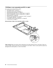
... be damaged by the cable guides, or a wire to be broken. 80 Hardware Maintenance Manual 1150 Base cover assembly and DC-in cable For access, remove these FRUs in order: • "1010 Battery pack" on page 52 • "1020 Bottom slot cover" on page 52 • "1040 Hard disk drive (HDD...; "1050 PCI Express Mini Card for wireless LAN" on page 56 • "1060 PCI Express Mini Card for wireless WAN" on page 57 • "1070 Keyboard" on page 59 • "1080 Top case assembly and microphone module" on page 61 • "1110 Speaker assembly" on page 66 • "1120 System board...
... be damaged by the cable guides, or a wire to be broken. 80 Hardware Maintenance Manual 1150 Base cover assembly and DC-in cable For access, remove these FRUs in order: • "1010 Battery pack" on page 52 • "1020 Bottom slot cover" on page 52 • "1040 Hard disk drive (HDD...; "1050 PCI Express Mini Card for wireless LAN" on page 56 • "1060 PCI Express Mini Card for wireless WAN" on page 57 • "1070 Keyboard" on page 59 • "1080 Top case assembly and microphone module" on page 61 • "1110 Speaker assembly" on page 66 • "1120 System board...

Harware Maintenance Manual
Page 90
...; "1050 PCI Express Mini Card for wireless LAN" on page 56 • "1060 PCI Express Mini Card for wireless WAN" on page 57 • "1070 Keyboard" on page 59 • "1080 Top case assembly and microphone module" on page 61 • "1110 Speaker assembly" on page 66 • "1120 System board... and fan assembly" on page 68 • "1140 LCD unit" on page 77 Removal steps of LCD panel and LCD cable 1 1 1 1 Step 1 Screw (quantity) M1.7 × 3 mm, flat-head, nylon-coated (4) Color Silver Torque 0.181 Nm (1.85 kgfcm) 84...
...; "1050 PCI Express Mini Card for wireless LAN" on page 56 • "1060 PCI Express Mini Card for wireless WAN" on page 57 • "1070 Keyboard" on page 59 • "1080 Top case assembly and microphone module" on page 61 • "1110 Speaker assembly" on page 66 • "1120 System board... and fan assembly" on page 68 • "1140 LCD unit" on page 77 Removal steps of LCD panel and LCD cable 1 1 1 1 Step 1 Screw (quantity) M1.7 × 3 mm, flat-head, nylon-coated (4) Color Silver Torque 0.181 Nm (1.85 kgfcm) 84...

Harware Maintenance Manual
Page 92
10 2040 Hinge kit For access, remove these FRUs in order: • "1010 Battery pack" on page 52 • "1020 Bottom slot cover" on page 52 • "1040 Hard disk drive (HDD)" ...; "1050 PCI Express Mini Card for wireless LAN" on page 56 • "1060 PCI Express Mini Card for wireless WAN" on page 57 • "1070 Keyboard" on page 59 • "1080 Top case assembly and microphone module" on page 61 • "1110 Speaker assembly" on page 66 • "1120 System board...
10 2040 Hinge kit For access, remove these FRUs in order: • "1010 Battery pack" on page 52 • "1020 Bottom slot cover" on page 52 • "1040 Hard disk drive (HDD)" ...; "1050 PCI Express Mini Card for wireless LAN" on page 56 • "1060 PCI Express Mini Card for wireless WAN" on page 57 • "1070 Keyboard" on page 59 • "1080 Top case assembly and microphone module" on page 61 • "1110 Speaker assembly" on page 66 • "1120 System board...

Harware Maintenance Manual
Page 94
...; "1050 PCI Express Mini Card for wireless LAN" on page 56 • "1060 PCI Express Mini Card for wireless WAN" on page 57 • "1070 Keyboard" on page 59 • "1080 Top case assembly and microphone module" on page 61 • "1110 Speaker assembly" on page 66 • "1120 System board... 68 • "1140 LCD unit" on page 77 • "2030 LCD panel and LCD cable" on page 84 • "2040 Hinge kit" on page 86 Removal steps of wireless LAN antenna assembly, wireless WAN antenna assembly, and LCD rear cover assembly 1 2 2 2 2 1 1 1 3 3 3 3 3 3 88 Hardware Maintenance Manual
...; "1050 PCI Express Mini Card for wireless LAN" on page 56 • "1060 PCI Express Mini Card for wireless WAN" on page 57 • "1070 Keyboard" on page 59 • "1080 Top case assembly and microphone module" on page 61 • "1110 Speaker assembly" on page 66 • "1120 System board... 68 • "1140 LCD unit" on page 77 • "2030 LCD panel and LCD cable" on page 84 • "2040 Hinge kit" on page 86 Removal steps of wireless LAN antenna assembly, wireless WAN antenna assembly, and LCD rear cover assembly 1 2 2 2 2 1 1 1 3 3 3 3 3 3 88 Hardware Maintenance Manual

Harware Maintenance Manual
Page 99
...CRU ID column. Once the access panel is removed, the specific CRU is a Self-service CRU; You may include the memory module, wireless card, keyboard, and palm rest with your product and are shipped with the replacement CRU; ThinkPad computers contain the following lists of a country ... Where you can install yourself, called a "Customer Replaceable Unit" or "CRU." you . Optional-service CRUs: These CRUs are installing the CRU, Lenovo will be charged for full details. An N in U. • FRU with a replacement part you are isolated parts within thirty (30) days ...
...CRU ID column. Once the access panel is removed, the specific CRU is a Self-service CRU; You may include the memory module, wireless card, keyboard, and palm rest with your product and are shipped with the replacement CRU; ThinkPad computers contain the following lists of a country ... Where you can install yourself, called a "Customer Replaceable Unit" or "CRU." you . Optional-service CRUs: These CRUs are installing the CRU, Lenovo will be charged for full details. An N in U. • FRU with a replacement part you are isolated parts within thirty (30) days ...

