Hardware Maintenance Manual
Page 3
...cables 69 1100 PCI Express Mini Card for wireless LAN . . 72 1110 Backup battery 74 1120 Bluetooth daughter card 74 1130 Keyboard 75 1140 Keyboard bezel 77 1150 LCD unit 79 1160 Top shielding assembly 82 i Related service information 39 Restoring the factory contents by using PC...-Doctor for DOS. . . . 28 Lenovo ThinkVantage Toolbox (Lenovo System Toolbox 31 PC-Doctor for CTO, CMV, and GAV products 24 Chapter 3. FRU replacement ...
...cables 69 1100 PCI Express Mini Card for wireless LAN . . 72 1110 Backup battery 74 1120 Bluetooth daughter card 74 1130 Keyboard 75 1140 Keyboard bezel 77 1150 LCD unit 79 1160 Top shielding assembly 82 i Related service information 39 Restoring the factory contents by using PC...-Doctor for DOS. . . . 28 Lenovo ThinkVantage Toolbox (Lenovo System Toolbox 31 PC-Doctor for CTO, CMV, and GAV products 24 Chapter 3. FRU replacement ...

Hardware Maintenance Manual
Page 4
Locations 101 Front view 101 Rear view 102 Bottom view 103 Chapter 10. Parts list 105 Overall 106 LCD FRUs 123 Keyboard 138 Miscellaneous parts 140 AC adapters 140 Power cords 141 Recovery discs 142 Windows 7 Home Basic (32 bit) DVDs. . . . 142 Windows 7 Home Premium (32 bit) ...
Locations 101 Front view 101 Rear view 102 Bottom view 103 Chapter 10. Parts list 105 Overall 106 LCD FRUs 123 Keyboard 138 Miscellaneous parts 140 AC adapters 140 Power cords 141 Recovery discs 142 Windows 7 Home Basic (32 bit) DVDs. . . . 142 Windows 7 Home Premium (32 bit) ...
Hardware Maintenance Manual
Page 34
... the following are not covered under warranty and some possible configurations of an incorrect ac adapter on laptop products The following Web site: http://support.lenovo.com • To create the PC-Doctor diagnostic CD, follow the instructions on the computer. 2. Identify the failing symptoms in as much detail as possible... • Fuses blown by attachment of a nonsupported device • Forgotten computer password (making the computer unusable) • Sticky keys caused by spilling a liquid onto the keyboard • Use of the computer, PC-Doctor might not run PC-Doctor.
... the following are not covered under warranty and some possible configurations of an incorrect ac adapter on laptop products The following Web site: http://support.lenovo.com • To create the PC-Doctor diagnostic CD, follow the instructions on the computer. 2. Identify the failing symptoms in as much detail as possible... • Fuses blown by attachment of a nonsupported device • Forgotten computer password (making the computer unusable) • Sticky keys caused by spilling a liquid onto the keyboard • Use of the computer, PC-Doctor might not run PC-Doctor.

Hardware Maintenance Manual
Page 36
...; Video Adapter • Serial Ports • Fixed Disks • Diskette Drives • Other Devices • Wireless LAN • Advanced Memory Tests • Keyboard • Video • Internal Speaker • Mouse • Diskette • System Load • Optical Drive Test • Intel WLAN Radio Test Notes:... • In the Keyboard test in Interactive Tests, the Fn key should be held down for DOS. • To test Digital Signature Chip, the security chip must be...
...; Video Adapter • Serial Ports • Fixed Disks • Diskette Drives • Other Devices • Wireless LAN • Advanced Memory Tests • Keyboard • Video • Internal Speaker • Mouse • Diskette • System Load • Optical Drive Test • Intel WLAN Radio Test Notes:... • In the Keyboard test in Interactive Tests, the Fn key should be held down for DOS. • To test Digital Signature Chip, the security chip must be...
Hardware Maintenance Manual
Page 40
... If the TrackPoint does not work , check the configuration as specified in the BIOS Setup Utility. Diagnostics ➙ Systemboard ➙ Keyboard 2. FRU tests FRU System board Power LCD unit Audio Speaker Applicable test 1. While the message, "To interrupt normal startup, press ...Enter," is not a hardware problem. Keyboard Hard disk drive Diskette drive Memory TrackPoint® or pointing device Touch Pad 1. Diagnostics ➙ Microprocessor/Coprocessor 2. Interactive Tests ...
... If the TrackPoint does not work , check the configuration as specified in the BIOS Setup Utility. Diagnostics ➙ Systemboard ➙ Keyboard 2. FRU tests FRU System board Power LCD unit Audio Speaker Applicable test 1. While the message, "To interrupt normal startup, press ...Enter," is not a hardware problem. Keyboard Hard disk drive Diskette drive Memory TrackPoint® or pointing device Touch Pad 1. Diagnostics ➙ Microprocessor/Coprocessor 2. Interactive Tests ...
Hardware Maintenance Manual
Page 49
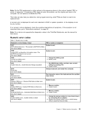
... Numeric error codes Symptom or error (beeps, if any number. System board. 0210 Stuck Key (two short beeps) Change keyboard, and restart the computer. 0211 Keyboard error (two short beeps) Run interactive tests of symptoms. If the symptom is not described there, go to EEPROM is failed.... (two short beeps) 0189 Invalid RFID configuration information area-The EEPROM checksum is displayed, check the narrative descriptions of the keyboard and the auxiliary input device. 0230 Shadow RAM error-Shadow RAM fails at offset nnnn. (two short beeps) System board. 0231 ...
... Numeric error codes Symptom or error (beeps, if any number. System board. 0210 Stuck Key (two short beeps) Change keyboard, and restart the computer. 0211 Keyboard error (two short beeps) Run interactive tests of symptoms. If the symptom is not described there, go to EEPROM is failed.... (two short beeps) 0189 Invalid RFID configuration information area-The EEPROM checksum is displayed, check the narrative descriptions of the keyboard and the auxiliary input device. 0230 Shadow RAM error-Shadow RAM fails at offset nnnn. (two short beeps) System board. 0231 ...
Hardware Maintenance Manual
Page 57
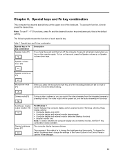
Note: To use the Power Manager. © Copyright Lenovo 2010, 2013 51 Special keys and Fn key combination Special key or Fn key combination Description Speaker mute (F1) If you mute the sound and ... volume down (F7) For Windows 7: Switch between the computer display and an external monitor, the Win+P key combination is to change the settings of the keyboard. this is the default setting. Windows will continue. The computer display becomes dimmer. To change the default brightness level, change the brightness level temporarily.
Note: To use the Power Manager. © Copyright Lenovo 2010, 2013 51 Special keys and Fn key combination Special key or Fn key combination Description Speaker mute (F1) If you mute the sound and ... volume down (F7) For Windows 7: Switch between the computer display and an external monitor, the Win+P key combination is to change the settings of the keyboard. this is the default setting. Windows will continue. The computer display becomes dimmer. To change the default brightness level, change the brightness level temporarily.
Hardware Maintenance Manual
Page 58
... the settings of the Power Option in the Control Panel or use this function, following device drivers must be installed on the keyboard illumination and then turn on the computer beforehand: • Power Management driver • OnScreen Display Utility • Wireless device ...drivers Fn + Spacebar (some models) Some models have a backlit keyboard. Special keys and Fn key combination (continued) Special key or Fn key combination Description Display brightness up (F8) The computer display becomes ...
... the settings of the Power Option in the Control Panel or use this function, following device drivers must be installed on the keyboard illumination and then turn on the computer beforehand: • Power Management driver • OnScreen Display Utility • Wireless device ...drivers Fn + Spacebar (some models) Some models have a backlit keyboard. Special keys and Fn key combination (continued) Special key or Fn key combination Description Display brightness up (F8) The computer display becomes ...

Hardware Maintenance Manual
Page 78
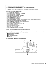
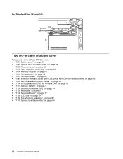
Attach the palm rest so that the two small projections of the keyboard bezel as shown in order: • "1010 Battery pack" on page 58 72 Hardware Maintenance Manual 2. Then fasten the screws to secure the palm rest. 1100 PCI Express Mini Card for wireless LAN For access, remove these FRUs in this figure. 3. Push the front side of the palm rest until it clicks into the guide holes of the palm rest firmly fit into place. 4. Close the LCD cover and turn the computer over.
Attach the palm rest so that the two small projections of the keyboard bezel as shown in order: • "1010 Battery pack" on page 58 72 Hardware Maintenance Manual 2. Then fasten the screws to secure the palm rest. 1100 PCI Express Mini Card for wireless LAN For access, remove these FRUs in this figure. 3. Push the front side of the palm rest until it clicks into the guide holes of the palm rest firmly fit into place. 4. Close the LCD cover and turn the computer over.

Hardware Maintenance Manual
Page 81
Removing or replacing a FRU 75 Removal steps of the Bluetooth daughter card 1 2 Step 1 Screw (quantity) M2 × 3 mm, wafer-head, nylon-coated (1) Color Black Torque 0.181 Nm (1.85 kgf-cm) When installing: Make sure that the connector on bottom side of the card is attached firmly to the system board. 1130 Keyboard For access, remove these FRUs in order: • "1010 Battery pack" on page 58 • "1020 Optical drive or travel cover" on page 58 • "1090 Palm rest assembly with cables" on page 69 Chapter 8.
Removing or replacing a FRU 75 Removal steps of the Bluetooth daughter card 1 2 Step 1 Screw (quantity) M2 × 3 mm, wafer-head, nylon-coated (1) Color Black Torque 0.181 Nm (1.85 kgf-cm) When installing: Make sure that the connector on bottom side of the card is attached firmly to the system board. 1130 Keyboard For access, remove these FRUs in order: • "1010 Battery pack" on page 58 • "1020 Optical drive or travel cover" on page 58 • "1090 Palm rest assembly with cables" on page 69 Chapter 8.

Hardware Maintenance Manual
Page 82
Removal steps of the keyboard 1 1 Step 1 Screw (quantity) M2 × 5 mm, wafer-head, nylon-coated (1) Color Black Torque 0.181 Nm (1.85 kgf-cm) 2 3 2 4 5 76 Hardware Maintenance Manual
Removal steps of the keyboard 1 1 Step 1 Screw (quantity) M2 × 5 mm, wafer-head, nylon-coated (1) Color Black Torque 0.181 Nm (1.85 kgf-cm) 2 3 2 4 5 76 Hardware Maintenance Manual

Hardware Maintenance Manual
Page 83
Secure the keyboard by tightening the screws from the bottom side of the computer. 1140 Keyboard bezel For access, remove these FRUs in this figure. 3. Attach the keyboard so that the front side of the keyboard is housed firmly, gently press the keys with your thumbs and try to slide the keyboard toward you. 4. To make sure that the keyboard edges are under the frame as follows: 1. Removing or replacing a FRU 77 Attach the connectors. 2. 6 Installation of the keyboard When installing the keyboard, do as shown in order: • "1010 Battery pack" on page 58 Chapter 8.
Secure the keyboard by tightening the screws from the bottom side of the computer. 1140 Keyboard bezel For access, remove these FRUs in this figure. 3. Attach the keyboard so that the front side of the keyboard is housed firmly, gently press the keys with your thumbs and try to slide the keyboard toward you. 4. To make sure that the keyboard edges are under the frame as follows: 1. Removing or replacing a FRU 77 Attach the connectors. 2. 6 Installation of the keyboard When installing the keyboard, do as shown in order: • "1010 Battery pack" on page 58 Chapter 8.

Hardware Maintenance Manual
Page 84
• "1020 Optical drive or travel cover" on page 58 • "1030 Thermal cover" on page 59 • "1060 Fan assembly" on page 62 • "1090 Palm rest assembly with cables" on page 69 • "1130 Keyboard" on page 75 Removal steps of the keyboard bezel 1 2 2 2 2 2 21 2 Step 1 2 Screw (quantity) M2.5 × 6.5 mm, wafer-head, nylon-coated (2) M2 × 3 mm, wafer-head, nylon-coated (7) Color Black Black Torque 0.181 Nm (1.85 kgf-cm) 0.181 Nm (1.85 kgfcm) 3 6 3 4 5 78 Hardware Maintenance Manual
• "1020 Optical drive or travel cover" on page 58 • "1030 Thermal cover" on page 59 • "1060 Fan assembly" on page 62 • "1090 Palm rest assembly with cables" on page 69 • "1130 Keyboard" on page 75 Removal steps of the keyboard bezel 1 2 2 2 2 2 21 2 Step 1 2 Screw (quantity) M2.5 × 6.5 mm, wafer-head, nylon-coated (2) M2 × 3 mm, wafer-head, nylon-coated (7) Color Black Black Torque 0.181 Nm (1.85 kgf-cm) 0.181 Nm (1.85 kgfcm) 3 6 3 4 5 78 Hardware Maintenance Manual

Hardware Maintenance Manual
Page 85
... 66 • "1090 Palm rest assembly with cables" on page 69 • "1100 PCI Express Mini Card for wireless LAN" on page 72 • "1130 Keyboard" on page 75 • "1140 Keyboard bezel" on page 77 Removal steps of the LCD unit 1 1 Chapter 8. Removing or replacing a FRU 79
... 66 • "1090 Palm rest assembly with cables" on page 69 • "1100 PCI Express Mini Card for wireless LAN" on page 72 • "1130 Keyboard" on page 75 • "1140 Keyboard bezel" on page 77 Removal steps of the LCD unit 1 1 Chapter 8. Removing or replacing a FRU 79

Hardware Maintenance Manual
Page 88
6 6 1160 Top shielding assembly For access, remove these FRUs in order: • "1010 Battery pack" on page 58 • "1020 Optical drive or travel cover" on page 58 • "1080 Wireless WAN slot cover and PCI Express Mini Card for wireless WAN" on page 66 • "1090 Palm rest assembly with cables" on page 69 • "1100 PCI Express Mini Card for wireless LAN" on page 72 • "1130 Keyboard" on page 75 • "1140 Keyboard bezel" on page 77 • "1150 LCD unit" on page 79 82 Hardware Maintenance Manual
6 6 1160 Top shielding assembly For access, remove these FRUs in order: • "1010 Battery pack" on page 58 • "1020 Optical drive or travel cover" on page 58 • "1080 Wireless WAN slot cover and PCI Express Mini Card for wireless WAN" on page 66 • "1090 Palm rest assembly with cables" on page 69 • "1100 PCI Express Mini Card for wireless LAN" on page 72 • "1130 Keyboard" on page 75 • "1140 Keyboard bezel" on page 77 • "1150 LCD unit" on page 79 82 Hardware Maintenance Manual
Hardware Maintenance Manual
Page 91
... wireless LAN" on page 72 • "1110 Backup battery" on page 74 • "1120 Bluetooth daughter card" on page 74 • "1130 Keyboard" on page 75 • "1140 Keyboard bezel" on page 77 • "1150 LCD unit" on page 79 • "1160 Top shielding assembly" on page 82 Location of major sensitive...
... wireless LAN" on page 72 • "1110 Backup battery" on page 74 • "1120 Bluetooth daughter card" on page 74 • "1130 Keyboard" on page 75 • "1140 Keyboard bezel" on page 77 • "1150 LCD unit" on page 79 • "1160 Top shielding assembly" on page 82 Location of major sensitive...

Hardware Maintenance Manual
Page 94
...; "1090 Palm rest assembly with cables" on page 69 • "1100 PCI Express Mini Card for wireless LAN" on page 72 • "1130 Keyboard" on page 75 • "1140 Keyboard bezel" on page 77 • "1150 LCD unit" on page 79 • "1160 Top shielding assembly" on page 82 88 Hardware Maintenance...
...; "1090 Palm rest assembly with cables" on page 69 • "1100 PCI Express Mini Card for wireless LAN" on page 72 • "1130 Keyboard" on page 75 • "1140 Keyboard bezel" on page 77 • "1150 LCD unit" on page 79 • "1160 Top shielding assembly" on page 82 88 Hardware Maintenance...
Hardware Maintenance Manual
Page 96
... for wireless LAN" on page 72 • "1110 Backup battery" on page 74 • "1120 Bluetooth daughter card" on page 74 • "1130 Keyboard" on page 75 • "1140 Keyboard bezel" on page 77 • "1150 LCD unit" on page 79 • "1160 Top shielding assembly" on page 82 • "1170 System...
... for wireless LAN" on page 72 • "1110 Backup battery" on page 74 • "1120 Bluetooth daughter card" on page 74 • "1130 Keyboard" on page 75 • "1140 Keyboard bezel" on page 77 • "1150 LCD unit" on page 79 • "1160 Top shielding assembly" on page 82 • "1170 System...
Hardware Maintenance Manual
Page 100
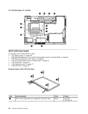
...; "1090 Palm rest assembly with cables" on page 69 • "1100 PCI Express Mini Card for wireless LAN" on page 72 • "1130 Keyboard" on page 75 • "1140 Keyboard bezel" on page 77 • "1150 LCD unit" on page 79 Removal steps of the LCD front bezel 1 1 1 1 Step 1 Screw (quantity) M2...
...; "1090 Palm rest assembly with cables" on page 69 • "1100 PCI Express Mini Card for wireless LAN" on page 72 • "1130 Keyboard" on page 75 • "1140 Keyboard bezel" on page 77 • "1150 LCD unit" on page 79 Removal steps of the LCD front bezel 1 1 1 1 Step 1 Screw (quantity) M2...

Hardware Maintenance Manual
Page 101
...; "1090 Palm rest assembly with cables" on page 69 • "1100 PCI Express Mini Card for wireless LAN" on page 72 • "1130 Keyboard" on page 75 • "1140 Keyboard bezel" on page 77 • "1150 LCD unit" on page 79 • "2010 LCD front bezel" on page 94 Removal steps of...
...; "1090 Palm rest assembly with cables" on page 69 • "1100 PCI Express Mini Card for wireless LAN" on page 72 • "1130 Keyboard" on page 75 • "1140 Keyboard bezel" on page 77 • "1150 LCD unit" on page 79 • "2010 LCD front bezel" on page 94 Removal steps of...


