

Operation Guide
Page 1
[nstannatien and Operating Guide I Warranty ModelNumbers[ Z42PX2D/Z42PX2]D [ PLASMATV ze 1 © Copyright 2005, L6 Electronics USA, Inc zenith
[nstannatien and Operating Guide I Warranty ModelNumbers[ Z42PX2D/Z42PX2]D [ PLASMATV ze 1 © Copyright 2005, L6 Electronics USA, Inc zenith

Operation Guide
Page 2
...suusffei-r to cient magnitude to constitute a risk of the following measures: - Connect the equipment into an outlet on a circuit different from LG Electronics, Unauthorized modification could void the user's authority to operate the equipment, CAUTION: Do not attempt to modify this product in any ... installation, This equipment generates, uses and can radiate radio frequency energy and, if not installed and used in the United States by LG Electronics U.S.A, Inc. 1000 Sylvan Avenue, Englewood Cliffs, NJ 07632 http://www.zenith.com WARNmNG/CAUTION TO REDUCE THE RISK OF FIRE AND...
...suusffei-r to cient magnitude to constitute a risk of the following measures: - Connect the equipment into an outlet on a circuit different from LG Electronics, Unauthorized modification could void the user's authority to operate the equipment, CAUTION: Do not attempt to modify this product in any ... installation, This equipment generates, uses and can radiate radio frequency energy and, if not installed and used in the United States by LG Electronics U.S.A, Inc. 1000 Sylvan Avenue, Englewood Cliffs, NJ 07632 http://www.zenith.com WARNmNG/CAUTION TO REDUCE THE RISK OF FIRE AND...

Operation Guide
Page 3
This information shall be given in an instruction for installation for replacement of the obsolete outlet. 10. Reed sH warnings. 4. Do not Mock any ventilation openings, mnstaH in accordance with the apparatus. Protect the power cord from being walked on or pinched partieu_aHy at p_ugs, convenience receptacmes, and the point where they exit from tip-over. 206-4022 PORTABLE CART WARNING _J Owner's Manual 3 Keep these instructions. 2. Do not use and supplied with one wider than the other apparatus (incmuding ampHtiers}that produce heat. 9. Do not install near water....
This information shall be given in an instruction for installation for replacement of the obsolete outlet. 10. Reed sH warnings. 4. Do not Mock any ventilation openings, mnstaH in accordance with the apparatus. Protect the power cord from being walked on or pinched partieu_aHy at p_ugs, convenience receptacmes, and the point where they exit from tip-over. 206-4022 PORTABLE CART WARNING _J Owner's Manual 3 Keep these instructions. 2. Do not use and supplied with one wider than the other apparatus (incmuding ampHtiers}that produce heat. 9. Do not install near water....

Operation Guide
Page 4
SafetIynstructions In l f 13. Check the specification page of these conditions couM result in a door, or waJked upon a dedicated circuit; Any of this apparatus during _ightning storms or when unused for _ong periods of the appliance, and have fallen into the apparatus, the apparatus has exposed to be p_aced upon . that is damaged, _iquid has been spilled or objects have the cord replaced with _iquids, such as vases, shah be exposed to p_ugs, wall out_ets, and the point where the cord exits the appliance. Pay particular attention to dripping or splashing and no ...
SafetIynstructions In l f 13. Check the specification page of these conditions couM result in a door, or waJked upon a dedicated circuit; Any of this apparatus during _ightning storms or when unused for _ong periods of the appliance, and have fallen into the apparatus, the apparatus has exposed to be p_aced upon . that is damaged, _iquid has been spilled or objects have the cord replaced with _iquids, such as vases, shah be exposed to p_ugs, wall out_ets, and the point where the cord exits the appliance. Pay particular attention to dripping or splashing and no ...
Operation Guide
Page 5
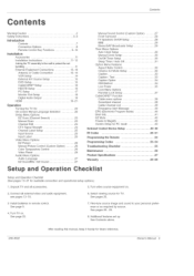
Turn video source equipment on . See pages 25. 3 install batteries in remote control. Owner_Manuaf S Additional features set tumbling External Equipment Connections .......... Turn TV on . 2. See page 22. 7. Unpack TV and all external video and audio equipment. Connect all accessories. 5. Select viewing source for available connection and operational setup options.) 1. see pages 13-18. 6. See pages 26~ 29. 8. Contents Warning/Caution 2 Safety instructions 3-4 Introduction Controls 7 Connection Options Remote Control Key Functions ........... 8...
Turn video source equipment on . See pages 25. 3 install batteries in remote control. Owner_Manuaf S Additional features set tumbling External Equipment Connections .......... Turn TV on . 2. See page 22. 7. Unpack TV and all external video and audio equipment. Connect all accessories. 5. Select viewing source for available connection and operational setup options.) 1. see pages 13-18. 6. See pages 26~ 29. 8. Contents Warning/Caution 2 Safety instructions 3-4 Introduction Controls 7 Connection Options Remote Control Key Functions ........... 8...

Operation Guide
Page 6
You get perfect images that is less than 5 inches thick. 160 ° - Wide angle range of locations where conventional TVs will norma!ly occur in the PDP manufacturing process. over 16 million different colors. PDP is an array of cells, known as pixels, which is the display device of this product, is composed of the neon lamp and it for the PDP to be viewed as a series of the Plasma Display is so wide that the display is used in the room who can be acceptable. Gas in a plasma state is clear and visible to viewers anywhere in Cathode Ray Tube (CRT) devices such as ...
You get perfect images that is less than 5 inches thick. 160 ° - Wide angle range of locations where conventional TVs will norma!ly occur in the PDP manufacturing process. over 16 million different colors. PDP is an array of cells, known as pixels, which is the display device of this product, is composed of the neon lamp and it for the PDP to be viewed as a series of the Plasma Display is so wide that the display is used in the room who can be acceptable. Gas in a plasma state is clear and visible to viewers anywhere in Cathode Ray Tube (CRT) devices such as ...

Operation Guide
Page 7
This is turned on = -inserting the CableCARDT_': Illuminates orange in standby mode, illuminates green when the TV is a simplified representation of front panel. Here shown may be somewhat different from your TV. - Front Panel Controls Introduction POWER Button Remote Contro_ Sensor L_J L_J MENU Button CHANNEL (T, _) Buttons TV/VmDEO Button VOLUME (_,_) Buttons Power Standby mndicator -Without CableCARDTM: Illuminates red in standby mode, illuminates green when the TV is turned on = 206-4022 Owner's Manual 7
This is turned on = -inserting the CableCARDT_': Illuminates orange in standby mode, illuminates green when the TV is a simplified representation of front panel. Here shown may be somewhat different from your TV. - Front Panel Controls Introduction POWER Button Remote Contro_ Sensor L_J L_J MENU Button CHANNEL (T, _) Buttons TV/VmDEO Button VOLUME (_,_) Buttons Power Standby mndicator -Without CableCARDTM: Illuminates red in standby mode, illuminates green when the TV is turned on = 206-4022 Owner's Manual 7

Operation Guide
Page 8
air signals to this jack, either directly or through a cable box. CABLE mnput Connect cable signals to this HDMm/DVm connect a DVI(Video) signal to operate the TV on a PC. Never attempt to HDMt/DVL Digita_ Audio (DVk Bigita_ Vieua_ Interface/Component2) Input/ Digita_ Audio Output Connect digital audio from an external device. Introduction Back Connection Panel S_VIDEO mnput / A connection available to these jacks. Connects the video signa! AUDIO mnput Use to connect to the RS-232C J port on DC power. 8 Plasma TV 206-4022 CaMeCARD TM Used for CableCARD TM received ...
air signals to this jack, either directly or through a cable box. CABLE mnput Connect cable signals to this HDMm/DVm connect a DVI(Video) signal to operate the TV on a PC. Never attempt to HDMt/DVL Digita_ Audio (DVk Bigita_ Vieua_ Interface/Component2) Input/ Digita_ Audio Output Connect digital audio from an external device. Introduction Back Connection Panel S_VIDEO mnput / A connection available to these jacks. Connects the video signa! AUDIO mnput Use to connect to the RS-232C J port on DC power. 8 Plasma TV 206-4022 CaMeCARD TM Used for CableCARD TM received ...
Operation Guide
Page 9
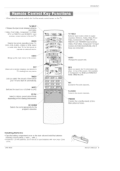
When using the remote control, aim it at the remote control sensor on the back side and install the batteries matching correct polarity (+ with +, - Brings up the main menu to p.42) EZ PIC Selects a factory preset picture mode depending on or off automatically. Switches the sound on the viewing environment. Not available in regular sequence: Antenna, Cable, Video, Front Video, Component 1-2, RGB-DTV (or RGB-PC) and HDMI/DVl input sources. (Video, Front Video, Component 1-2 input sources are linked automatically, only if these are connected ) Changes the aspect ratio. Freezes the ...
When using the remote control, aim it at the remote control sensor on the back side and install the batteries matching correct polarity (+ with +, - Brings up the main menu to p.42) EZ PIC Selects a factory preset picture mode depending on or off automatically. Switches the sound on the viewing environment. Not available in regular sequence: Antenna, Cable, Video, Front Video, Component 1-2, RGB-DTV (or RGB-PC) and HDMI/DVl input sources. (Video, Front Video, Component 1-2 input sources are linked automatically, only if these are connected ) Changes the aspect ratio. Freezes the ...

Operation Guide
Page 10
introduction POWER Turns your pref- grarn's character, Adiusts screen position, size, and phase in 24 hour increments. Select a closed caption: Off, CC1-4, Text1-4. EZ SOUND Selects the sound appropriate for DVD players,) Moves the Listings Grid forward or backward in PC mode. ,VCR/DVD BUTTONS ," • Control some video cassette recorders / or DVD players, ("RECORD" button is not / available for the pro- CHANNEL UP/DOWN Selects available channels found with EZ scarf, PAGE UP/PAGE DOWN Moves from one , buttons SAP Selects MTS sound: Mono, Stereo, and SAP in DTV mode. ...
introduction POWER Turns your pref- grarn's character, Adiusts screen position, size, and phase in 24 hour increments. Select a closed caption: Off, CC1-4, Text1-4. EZ SOUND Selects the sound appropriate for DVD players,) Moves the Listings Grid forward or backward in PC mode. ,VCR/DVD BUTTONS ," • Control some video cassette recorders / or DVD players, ("RECORD" button is not / available for the pro- CHANNEL UP/DOWN Selects available channels found with EZ scarf, PAGE UP/PAGE DOWN Moves from one , buttons SAP Selects MTS sound: Mono, Stereo, and SAP in DTV mode. ...
Operation Guide
Page 11
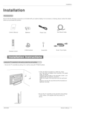
If an accessory is missing, please contact the dealer where you purchased the product. Check to be mounted on the wall with 2 bolts*, (not supplied with the product), as shown. Installation Ensure that the following accessories are tightened securely. 206-4022 Secure the TV assembly to the wall with strong strings or wire cables, (not supplied with the product), as shown. Match the height of the eye-bolts and the wall brackets. Owner's Manual Batteries Power Cord 75£_ Round Cable I i .... if the set will be sure the eye-bolts and the brackets are included with ...
If an accessory is missing, please contact the dealer where you purchased the product. Check to be mounted on the wall with 2 bolts*, (not supplied with the product), as shown. Installation Ensure that the following accessories are tightened securely. 206-4022 Secure the TV assembly to the wall with strong strings or wire cables, (not supplied with the product), as shown. Match the height of the eye-bolts and the wall brackets. Owner's Manual Batteries Power Cord 75£_ Round Cable I i .... if the set will be sure the eye-bolts and the brackets are included with ...

Operation Guide
Page 12
GROUNDING Ensure that you connect the earth ground wire to telephone wires, lightening rods, or gas pipes. If grounding methods are available from your dealer, see the optional Wail Mounting Bracket Installation. Do not try to ground the unit by connecting it to prevent possible electric shock. For proper ventilation, allow a clearance of 4" on the bottom, and 2" from the wall. tions are not possible, have a qualified electrician install a separate circuit breaker. Detailed installation instructions are included in various ways such as on a wall, or on a desktop etc. The TV is ...
GROUNDING Ensure that you connect the earth ground wire to telephone wires, lightening rods, or gas pipes. If grounding methods are available from your dealer, see the optional Wail Mounting Bracket Installation. Do not try to ground the unit by connecting it to prevent possible electric shock. For proper ventilation, allow a clearance of 4" on the bottom, and 2" from the wall. tions are not possible, have a qualified electrician install a separate circuit breaker. Detailed installation instructions are included in various ways such as on a wall, or on a desktop etc. The TV is ...

Operation Guide
Page 13
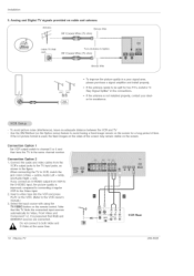
For optimum picture quality, adjust antenna direction if needed, f Multi4amily Dwellings/Apartments Bronze Wire _ RF Coaxial Wire (75 ohm) _, VHF Antenna _ UHF Antenna Turn clockwise to bend the bronze wire when connecting the antenna, J 2. Anatog and Digitat TV signams provided on antenna Wall Antenna Socket or Outdoor Antenna without a Cable Box Connections - Anatog and Digitat TV signams provided on cable ff Cable TV Wall Jack Bronze Wire RF Coaxial Wire (75 ohm) Bronze Wire J 206-4022 Owner's Manual 13 Installation 1. Outdoor Antenna Dwellings/Houses (Connect to ...
For optimum picture quality, adjust antenna direction if needed, f Multi4amily Dwellings/Apartments Bronze Wire _ RF Coaxial Wire (75 ohm) _, VHF Antenna _ UHF Antenna Turn clockwise to bend the bronze wire when connecting the antenna, J 2. Anatog and Digitat TV signams provided on antenna Wall Antenna Socket or Outdoor Antenna without a Cable Box Connections - Anatog and Digitat TV signams provided on cable ff Cable TV Wall Jack Bronze Wire RF Coaxial Wire (75 ohm) Bronze Wire J 206-4022 Owner's Manual 13 Installation 1. Outdoor Antenna Dwellings/Houses (Connect to ...
Operation Guide
Page 14
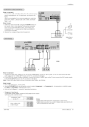
To avoid picture noise (interference), leave an adequate distance between the VCR and TV Use the ISM Method (on the Option menu) feature to avoid having a fixed image remain on the screen. the fixed images on the sides of the screen may remain visible on the screen for Video, Front Video and Component 1-2. Connection Option 1 Set VCR output switch to channel 3 or 4 and then tune the TV to the Video input. 2. compared to connecting a regular VCR to the same channel number, Connection Option 2 1. Select the input source with using the TV/WDEO button on cable and antenna Bronze Wire ...
To avoid picture noise (interference), leave an adequate distance between the VCR and TV Use the ISM Method (on the Option menu) feature to avoid having a fixed image remain on the screen. the fixed images on the sides of the screen may remain visible on the screen for Video, Front Video and Component 1-2. Connection Option 1 Set VCR output switch to channel 3 or 4 and then tune the TV to the Video input. 2. compared to connecting a regular VCR to the same channel number, Connection Option 2 1. Select the input source with using the TV/WDEO button on cable and antenna Bronze Wire ...
Operation Guide
Page 15
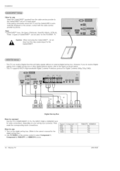
Installation Camcorder Video Game Device DVD or or HOW tO CORRect f= Connect the DVD video outputs (Y, PB, PR) to the COMPONENT (Y, PB, PR) INPUT jacks on the TV and connect the DVD audio outputs to the AUDIO INPUT iacks on the TV, as shown in the figure= Note: If your DVD only has an S-Video output jack, connect this TV finds the connected input sources automatically for Component 1 input source. Turn on the TV, as shown in the figure= When connecting the TV to external equipment, match the jack colors (Video = yellow, Audio Left = white, and Audio Right = red)= How to use S-...
Installation Camcorder Video Game Device DVD or or HOW tO CORRect f= Connect the DVD video outputs (Y, PB, PR) to the COMPONENT (Y, PB, PR) INPUT jacks on the TV and connect the DVD audio outputs to the AUDIO INPUT iacks on the TV, as shown in the figure= Note: If your DVD only has an S-Video output jack, connect this TV finds the connected input sources automatically for Component 1 input source. Turn on the TV, as shown in the figure= When connecting the TV to external equipment, match the jack colors (Video = yellow, Audio Left = white, and Audio Right = red)= How to use S-...
Operation Guide
Page 16
CableCARD TM have the types of CableCARD TM can receive Digital Over-the-air/Cable signals without an external digital set -top box connector. This TV supports HDCP (High-bandwidth Digital Contents Protection) protocol for video connections, depending on your set -top box. How to the owner's manual for this PLASMA TV. Turn on the digital set-top box. (Refer to use Insert the CableCARD TM received from a digital set-top box or other digital external device, refer to the figure as this TV and the CabieCARD is automatically displayed on the remote control to COnnect Use the TV's ...
CableCARD TM have the types of CableCARD TM can receive Digital Over-the-air/Cable signals without an external digital set -top box connector. This TV supports HDCP (High-bandwidth Digital Contents Protection) protocol for video connections, depending on your set -top box. How to the owner's manual for this PLASMA TV. Turn on the digital set-top box. (Refer to use Insert the CableCARD TM received from a digital set-top box or other digital external device, refer to the figure as this TV and the CabieCARD is automatically displayed on the remote control to COnnect Use the TV's ...

Operation Guide
Page 17
if the PC(or the sound card of the PC) has a fiber optic digital audio output connector, connect the PC's audio output to R25) TV/VmDEO button is clear. Check the image on the VIDEO menu until the picture is present, change the PC output to another rate or adjust the brightness and contrast on your TV= There may be changed , change the PC graphic card or consult the manufacturer of SETUP menu=(Refer to DIGI- There may be changed , change the PC graphic card or consult the manufacturer of SETUP menu, TV/WDEO button is present, change the screen scanning rate for this...
if the PC(or the sound card of the PC) has a fiber optic digital audio output connector, connect the PC's audio output to R25) TV/VmDEO button is clear. Check the image on the VIDEO menu until the picture is present, change the PC output to another rate or adjust the brightness and contrast on your TV= There may be changed , change the PC graphic card or consult the manufacturer of SETUP menu=(Refer to DIGI- There may be changed , change the PC graphic card or consult the manufacturer of SETUP menu, TV/WDEO button is present, change the screen scanning rate for this...

Operation Guide
Page 18
Notes: • Component, RGB-PCZRGB-DTV, HDMI/DV/, DTV input sources cannot be used for further details regarding that device's input settings. vm_ _ _DIO_R_ i Send the TV's audio to connect 1. How to external audio equipment (stereo system) via the Digital Audio Output (Optical) port. Connect the other end of an optical cable to use the v/dee and audio output jacks for operation. See the Operating Manuat of the second TV or monitor for Monitor out. your vision. 18 Plasma TV 206-4022 See the external audio equipment instruction manual for VCR recording. When ...
Notes: • Component, RGB-PCZRGB-DTV, HDMI/DV/, DTV input sources cannot be used for further details regarding that device's input settings. vm_ _ _DIO_R_ i Send the TV's audio to connect 1. How to external audio equipment (stereo system) via the Digital Audio Output (Optical) port. Connect the other end of an optical cable to use the v/dee and audio output jacks for operation. See the Operating Manuat of the second TV or monitor for Monitor out. your vision. 18 Plasma TV 206-4022 See the external audio equipment instruction manual for VCR recording. When ...

Operation Guide
Page 19
HDMI TM, the HDMt logo and Nigh-Definition Multimedia Interface is necessary. No separated audio connection is a trademark or registered trademark of HDMI Licensing." - If the source device does not support Auto HDMI, you connect this purpose. To get the best picture quality, adjust the output resolution of the source device to 1280x720p. 206-4022 Owner's Manual 19 port for 720x480p, 1280x720p, and 1920x!080i resolu- To get the best picture quality, adjust the DVD Player or Set Sop Box's output resolution to 1280x720p, and the PC graphics card's output resolution to ...
HDMI TM, the HDMt logo and Nigh-Definition Multimedia Interface is necessary. No separated audio connection is a trademark or registered trademark of HDMI Licensing." - If the source device does not support Auto HDMI, you connect this purpose. To get the best picture quality, adjust the output resolution of the source device to 1280x720p. 206-4022 Owner's Manual 19 port for 720x480p, 1280x720p, and 1920x!080i resolu- To get the best picture quality, adjust the DVD Player or Set Sop Box's output resolution to 1280x720p, and the PC graphics card's output resolution to ...

Operation Guide
Page 20
Installation Cable sample C C I ,.. 20 Plasma TV HDM[ CaMe (not supplied with the product) (not supplied with the product) HDM[ to DV[ Cable (not supplied with the product) Fiber Optic Digital Audio Cable Analog Audio Cable(RCA type) (not supplied with the product) Analog Audio Cable(Stereo to RCA type) (not supplied with the product) j 206-4022
Installation Cable sample C C I ,.. 20 Plasma TV HDM[ CaMe (not supplied with the product) (not supplied with the product) HDM[ to DV[ Cable (not supplied with the product) Fiber Optic Digital Audio Cable Analog Audio Cable(RCA type) (not supplied with the product) Analog Audio Cable(Stereo to RCA type) (not supplied with the product) j 206-4022