
Owners Manual
Page 2
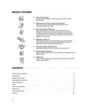
... at Its optimum level for selected cycles, a Child Lock The Child lock prevents chitdren from pressing any button to Use the Washer 14 Maintenance ... 17 Troubleshooting Guide ......... 20 Warranty ... 23 2
... at Its optimum level for selected cycles, a Child Lock The Child lock prevents chitdren from pressing any button to Use the Washer 14 Maintenance ... 17 Troubleshooting Guide ......... 20 Warranty ... 23 2
Owners Manual
Page 20
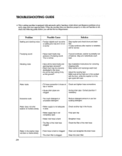
... distributed in firm contact with the floor, whi_e the washer is not completely open tap Straighten hose Check the filter of the inlet hose clogged. TROUBLESHOOTING GUIDE .... ....... * This _vashing machine is equipped with automatic safety [unctions which detect and diagnnse problems at Check and tighten hose connections tap or washer, •...
... distributed in firm contact with the floor, whi_e the washer is not completely open tap Straighten hose Check the filter of the inlet hose clogged. TROUBLESHOOTING GUIDE .... ....... * This _vashing machine is equipped with automatic safety [unctions which detect and diagnnse problems at Check and tighten hose connections tap or washer, •...
Owners Manual
Page 21
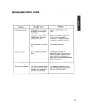
TROUBLESHOOTING GUIDE i :i :, Problem Washer does not start Possible Cause • Electrical power cord may not be plugged in wall outlet., Reset circuit breaker or replace fuse ...
TROUBLESHOOTING GUIDE i :i :, Problem Washer does not start Possible Cause • Electrical power cord may not be plugged in wall outlet., Reset circuit breaker or replace fuse ...

Owners Manual
Page 22
..., Unplug the power plug Call for service • The water overfills due to allow proper spinning • Is the door opened or not completely closed? TROUBLESHOOTING GUIDE ....
..., Unplug the power plug Call for service • The water overfills due to allow proper spinning • Is the door opened or not completely closed? TROUBLESHOOTING GUIDE ....

Service Manual
Page 3
... 7-1. ERROR DISPLAY ...18 8. DRUM & TUB ASSEMBLY 42 10-3. PARTS IDENTIFICATION ...7 4. HOW TO CHECK THE WATER LEVEL FREQUENCY 17 7-4. FAULT DIAGNOSIS AND TROUBLESHOOTING 23 9. WIRING DIAGRAM/PROGRAM CHART 14 7. ERROR DIAGNOSIS AND CHECK LIST 20 8-1. QC TEST MODE...17 7-3. SPECIFICATIONS ...3 2. OPERATION ...11 6. DISASSEMBLY INSTRUCTIONS 32 10. EXPLODED VIEW ......
... 7-1. ERROR DISPLAY ...18 8. DRUM & TUB ASSEMBLY 42 10-3. PARTS IDENTIFICATION ...7 4. HOW TO CHECK THE WATER LEVEL FREQUENCY 17 7-4. FAULT DIAGNOSIS AND TROUBLESHOOTING 23 9. WIRING DIAGRAM/PROGRAM CHART 14 7. ERROR DIAGNOSIS AND CHECK LIST 20 8-1. QC TEST MODE...17 7-3. SPECIFICATIONS ...3 2. OPERATION ...11 6. DISASSEMBLY INSTRUCTIONS 32 10. EXPLODED VIEW ......
Service Manual
Page 9
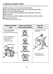
... The appliance should be installed as follows: REMOVE THE SHIPPING BOLTS INSTALL THE APPLIANCE ON A FLAT AND FIRM SURFACE Remove the 4 shipping bolts with the troubleshooting guide. ADJUST THE LEVELING Turn the leveling feet to lower. 8 Keep the shipping bolts and spanner for future use. counterclockwise to adjust the appliance. Check...
... The appliance should be installed as follows: REMOVE THE SHIPPING BOLTS INSTALL THE APPLIANCE ON A FLAT AND FIRM SURFACE Remove the 4 shipping bolts with the troubleshooting guide. ADJUST THE LEVELING Turn the leveling feet to lower. 8 Keep the shipping bolts and spanner for future use. counterclockwise to adjust the appliance. Check...
Service Manual
Page 18
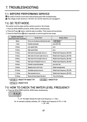
... level frequency ( x.1 kHz ). QC TEST MODE. The washer must be empty and the controls must be in . 7-2. Number of electric shock when disconnecting parts while troubleshooting. 7. HOW TO CHECK THE WATER LEVEL FREQUENCY Press the SPIN SPEED and SOIL LEVEL button simultaneously. Press the SPIN SPEED and SOIL LEVEL buttons simultaneously...
... level frequency ( x.1 kHz ). QC TEST MODE. The washer must be empty and the controls must be in . 7-2. Number of electric shock when disconnecting parts while troubleshooting. 7. HOW TO CHECK THE WATER LEVEL FREQUENCY Press the SPIN SPEED and SOIL LEVEL button simultaneously. Press the SPIN SPEED and SOIL LEVEL buttons simultaneously...

Service Manual
Page 24
... voltage between the 2 FILTER ASSEMBLY NO connectors 120 V AC? First of all, check the connection of electric shock if disconnecting parts while troubleshooting. 2. Are the connectors (2) on ? FAULT DIAGNOSIS AND TROUBLESHOOTING CAUTION 1. YES Is the LED (1) on the PWB loose? YES NO Replace MAIN PWB ASSEMBLY. NO Is wire of the DISPLAY...
... voltage between the 2 FILTER ASSEMBLY NO connectors 120 V AC? First of all, check the connection of electric shock if disconnecting parts while troubleshooting. 2. Are the connectors (2) on ? FAULT DIAGNOSIS AND TROUBLESHOOTING CAUTION 1. YES Is the LED (1) on the PWB loose? YES NO Replace MAIN PWB ASSEMBLY. NO Is wire of the DISPLAY...

