
Owners Manual
Page 3
...-maintenance instructions or published user-repair instructions that is properly installed and grounded in , or spotted with controls. • Do not repair or replace any part of tire, electric shock, or injury to the wash water. Close supervision of children is necessary when the washer Is used for several minutes. The...
...-maintenance instructions or published user-repair instructions that is properly installed and grounded in , or spotted with controls. • Do not repair or replace any part of tire, electric shock, or injury to the wash water. Close supervision of children is necessary when the washer Is used for several minutes. The...
Owners Manual
Page 18
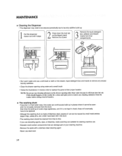
... inserts to remove any excess laundry additives, * Clean the drawer opening using water and a small brush * Follow the illustrations in reverse order to replace the parts to their proper location NOTE: Do not use any cleaning substance on the drawer opening olher titan water because it is not kept in check... pins, etc ) which have been left in places where it cannot be seen and it is made of Stainless steel, specks of rust can damage part of laundry° ,.
... inserts to remove any excess laundry additives, * Clean the drawer opening using water and a small brush * Follow the illustrations in reverse order to replace the parts to their proper location NOTE: Do not use any cleaning substance on the drawer opening olher titan water because it is not kept in check... pins, etc ) which have been left in places where it cannot be seen and it is made of Stainless steel, specks of rust can damage part of laundry° ,.
Owners Manual
Page 23
.... CIC Call 1-87Z_714_7486(24 hours a day, 365 days per year) and select the appropriate option from the Dateof Pumhoce PARTS (except as evidence of the Date of Purchase for other rights that vary from state to state° THIS LIMITED WARRANTY...http://www_Igservtce.com 23 OoBox 240007 201 James Record Road Huntsville, Alabama 35824 ATTN; Lifetime ReplacementUnits and Repair Parts may not apply to your nearest LG Authorized Service Centers ReplacemenUt nitsend RepairPartsore warrantedfor the remainingportionof the odginal unit's warrantyperiod. Electronic Control Board: 2 ...
.... CIC Call 1-87Z_714_7486(24 hours a day, 365 days per year) and select the appropriate option from the Dateof Pumhoce PARTS (except as evidence of the Date of Purchase for other rights that vary from state to state° THIS LIMITED WARRANTY...http://www_Igservtce.com 23 OoBox 240007 201 James Record Road Huntsville, Alabama 35824 ATTN; Lifetime ReplacementUnits and Repair Parts may not apply to your nearest LG Authorized Service Centers ReplacemenUt nitsend RepairPartsore warrantedfor the remainingportionof the odginal unit's warrantyperiod. Electronic Control Board: 2 ...

Service Manual
Page 3
... CHECK LIST 20 8-1. DISASSEMBLY INSTRUCTIONS 32 10. ERROR DISPLAY ...18 8. CONTENTS 1. SPECIFICATIONS ...3 2. HOW TO CHECK THE WATER LEVEL FREQUENCY 17 7-4. FAULT DIAGNOSIS AND TROUBLESHOOTING 23 9. PARTS IDENTIFICATION ...7 4. WIRING DIAGRAM/PROGRAM CHART 14 7. BEFORE PERFORMING SERVICE 17 7-2. DRUM & TUB ASSEMBLY 42 10-3.
... CHECK LIST 20 8-1. DISASSEMBLY INSTRUCTIONS 32 10. ERROR DISPLAY ...18 8. CONTENTS 1. SPECIFICATIONS ...3 2. HOW TO CHECK THE WATER LEVEL FREQUENCY 17 7-4. FAULT DIAGNOSIS AND TROUBLESHOOTING 23 9. PARTS IDENTIFICATION ...7 4. WIRING DIAGRAM/PROGRAM CHART 14 7. BEFORE PERFORMING SERVICE 17 7-2. DRUM & TUB ASSEMBLY 42 10-3.
Service Manual
Page 7
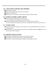
.... 6 When Washing, it is in operation While Door Lock lights turn on. When Rinsing, it continuously operates after completion of water supply at the upper part of intertial rotating, through the operation is not 25.5 kHz (It can lock the washer while it continuously operates for 3 seconds to prevent unwanted use...
.... 6 When Washing, it is in operation While Door Lock lights turn on. When Rinsing, it continuously operates after completion of water supply at the upper part of intertial rotating, through the operation is not 25.5 kHz (It can lock the washer while it continuously operates for 3 seconds to prevent unwanted use...

Service Manual
Page 8
3. PARTS IDENTIFICATION ACCESSORIES Water Circulation Nozzle A Safety Cover (PLC Moderm) 7
3. PARTS IDENTIFICATION ACCESSORIES Water Circulation Nozzle A Safety Cover (PLC Moderm) 7
Service Manual
Page 18
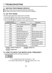
.... 10 times Circulation pump turns on. 11 times Drain pump turns on for example a display indicating 241: a Water level frequency of electric shock when disconnecting parts while troubleshooting. Press the SPIN SPEED and SOIL LEVEL buttons simultaneously. 2. BEFORE PERFORMING SERVICE Be careful of 241 x.1 kHz = 24.1 kHz 17 TROUBLESHOOTING 7-1. Display Status...
.... 10 times Circulation pump turns on. 11 times Drain pump turns on for example a display indicating 241: a Water level frequency of electric shock when disconnecting parts while troubleshooting. Press the SPIN SPEED and SOIL LEVEL buttons simultaneously. 2. BEFORE PERFORMING SERVICE Be careful of 241 x.1 kHz = 24.1 kHz 17 TROUBLESHOOTING 7-1. Display Status...

Service Manual
Page 24
Be careful of each electrical terminal with the wiring diagram. 3. First of all, check the connection of electric shock if disconnecting parts while troubleshooting. 2. NO POWER Connector Is the supplied voltage 110/120 V AC? YES NO Replace MAIN PWB ASSEMBLY. NO Is wire of the DISPLAY PWB ...
Be careful of each electrical terminal with the wiring diagram. 3. First of all, check the connection of electric shock if disconnecting parts while troubleshooting. 2. NO POWER Connector Is the supplied voltage 110/120 V AC? YES NO Replace MAIN PWB ASSEMBLY. NO Is wire of the DISPLAY PWB ...
Service Manual
Page 25
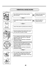
...with a Level and check that the washer is not stable, adjust feet accordingly. NO YES Move the washer or reinforce the floor. Put an unbalance part (rubber) inside of clothing. When the machine is spinning in high spin (Refer to 3 kg) of drum and start /pause button in high ... as follows: Check the leveling of the washer. YES If it is spinning in sequence. VIBRATION & NOISE IN SPIN Base Packing Level Unbalance Part Higher LNouctk Adjustable feet Lower Adjustable feet Have all the transit bolts and base packing been removed? When the machine is stable. All lock nuts...
...with a Level and check that the washer is not stable, adjust feet accordingly. NO YES Move the washer or reinforce the floor. Put an unbalance part (rubber) inside of clothing. When the machine is spinning in high spin (Refer to 3 kg) of drum and start /pause button in high ... as follows: Check the leveling of the washer. YES If it is spinning in sequence. VIBRATION & NOISE IN SPIN Base Packing Level Unbalance Part Higher LNouctk Adjustable feet Lower Adjustable feet Have all the transit bolts and base packing been removed? When the machine is stable. All lock nuts...
Service Manual
Page 26
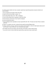
... 100 rpm). If it still has severe vibration and noise, regulate a specific spin speed that generates excessive vibration and noise as follows: 1) Put an unbalance part (rubber) inside of 600 rpm, it can not reduce the spin speed. 10) If vibration and noise are reduced, press the Quick Cycle button to...
... 100 rpm). If it still has severe vibration and noise, regulate a specific spin speed that generates excessive vibration and noise as follows: 1) Put an unbalance part (rubber) inside of 600 rpm, it can not reduce the spin speed. 10) If vibration and noise are reduced, press the Quick Cycle button to...

Service Manual
Page 33
DRAWER CONTROL PANEL ASSEMBLY Disconnect the Display PWB Assembly connector from the Control Panel Assembly. Pull out the drawer and unscrew 2 screws. Disassemble the Display PWB Assembly. 32 DISPLAY PWB ASSEMBLY Unscrew the 9 screws from Trans cable. TOP PLATE ASSEMBLY Unscrew 2 screws on the back of the outlet before disassembling and repairing the parts. DISASSEMBLY INSTRUCTIONS Be sure to unplug the machine out of the top plate. 9. Pull the top plate backward and upward as shown. Lift the left side of the Control Panel Assembly and pull it out.
DRAWER CONTROL PANEL ASSEMBLY Disconnect the Display PWB Assembly connector from the Control Panel Assembly. Pull out the drawer and unscrew 2 screws. Disassemble the Display PWB Assembly. 32 DISPLAY PWB ASSEMBLY Unscrew the 9 screws from Trans cable. TOP PLATE ASSEMBLY Unscrew 2 screws on the back of the outlet before disassembling and repairing the parts. DISASSEMBLY INSTRUCTIONS Be sure to unplug the machine out of the top plate. 9. Pull the top plate backward and upward as shown. Lift the left side of the Control Panel Assembly and pull it out.

Service Manual
Page 35
Disassemble the 4 connectors from the NOISE FILTER. Disassemble two (or three) connectors from the valves. Pull out the drawer. Unscrew the nut at the lower part of the cabinet. Wire Color Blue Housing (OR-BK) White Housing (WH-BK) Blue Housing (GY-BK) Red Housing (BL-BK) Unscrew 2 screws from the TOP BRACKET. 34 Unscrew a screw from the back of the dispenser. Push out the DISPENSER ASSEMBLY after unscrew 2 screws. Disassemble the top plate assembly.
Disassemble the 4 connectors from the NOISE FILTER. Disassemble two (or three) connectors from the valves. Pull out the drawer. Unscrew the nut at the lower part of the cabinet. Wire Color Blue Housing (OR-BK) White Housing (WH-BK) Blue Housing (GY-BK) Red Housing (BL-BK) Unscrew 2 screws from the TOP BRACKET. 34 Unscrew a screw from the back of the dispenser. Push out the DISPENSER ASSEMBLY after unscrew 2 screws. Disassemble the top plate assembly.


