
User Guide
Page 4
... computer system, and other attached devices is turned off. Tie down holding only the stand base. Once assembled take the monitor up the monitor, ensure that the power to perpendicularity direction. 4. A3 Connecting the stand 1. Connecting the Display Before setting up carefully and face ...the front side Important This illustration depicts the general model of connection. Your monitor may fall and get damaged or injure your foot. Assemble the Stand Base(Front, Rear) into the Stand Body in the picture. ...
... computer system, and other attached devices is turned off. Tie down holding only the stand base. Once assembled take the monitor up the monitor, ensure that the power to perpendicularity direction. 4. A3 Connecting the stand 1. Connecting the Display Before setting up carefully and face ...the front side Important This illustration depicts the general model of connection. Your monitor may fall and get damaged or injure your foot. Assemble the Stand Base(Front, Rear) into the Stand Body in the picture. ...

User Guide
Page 5
Change your lock on a flat surface. 2. If you can't release the stand base even the locking rib is at a release position, Please push the indicated rib down on the cushion or soft cloth. 3. Put a cushion or soft cloth on the product as it follows and turn it . 4. Pull out the stand to remove. Connecting the Display Disassembling the stand 1. A4 Place the monitor face down and retry it in the arrow direction.
Change your lock on a flat surface. 2. If you can't release the stand base even the locking rib is at a release position, Please push the indicated rib down on the cushion or soft cloth. 3. Put a cushion or soft cloth on the product as it follows and turn it . 4. Pull out the stand to remove. Connecting the Display Disassembling the stand 1. A4 Place the monitor face down and retry it in the arrow direction.
User Guide
Page 6
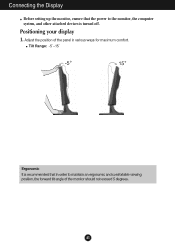
Adjust the position of the monitor should not exceed 5 degrees. Tilt Range: -5˚~15˚ Ergonomic It is turned off. A5 Positioning your display 1. Connecting the Display Before setting up the monitor, ensure that the power to the monitor, the computer system, and other attached devices is recommended that in order to maintain an ergonomic and comfortable viewing position, the forward tilt angle of the panel in various ways for maximum comfort.
Adjust the position of the monitor should not exceed 5 degrees. Tilt Range: -5˚~15˚ Ergonomic It is turned off. A5 Positioning your display 1. Connecting the Display Before setting up the monitor, ensure that the power to the monitor, the computer system, and other attached devices is recommended that in order to maintain an ergonomic and comfortable viewing position, the forward tilt angle of the panel in various ways for maximum comfort.

User Guide
Page 7
A Connect D-sub Cable (PC) B Connect D-sub Cable (Mac) NOTE This is executed automatically. When monitor power is turned on . When you encounter problems such as blurry screen, blurred letters, screen flicker or tilted screen while using the device ...outlet type Mac adapter For Apple Macintosh use shielded signal interface cables (D-sub 15 pin cable) with optimal display settings.When the user connects the monitor for the first time, this function automatically adjusts the display to maintain standard compliance for individual input signals. 'AUTO/SET' Function? This function ...
A Connect D-sub Cable (PC) B Connect D-sub Cable (Mac) NOTE This is executed automatically. When monitor power is turned on . When you encounter problems such as blurry screen, blurred letters, screen flicker or tilted screen while using the device ...outlet type Mac adapter For Apple Macintosh use shielded signal interface cables (D-sub 15 pin cable) with optimal display settings.When the user connects the monitor for the first time, this function automatically adjusts the display to maintain standard compliance for individual input signals. 'AUTO/SET' Function? This function ...

User Guide
Page 13
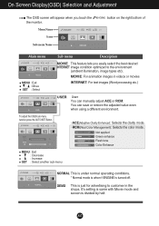
A12 Press the MENU Button, then the main menu of selecting and adjusting an item using the OSD system. Listed below are the icons, icon names, and icon descriptions of the all items shown on the monitor may differ from the manual. On Screen Display(OSD) Selection and Adjustment You were introduced to select sub-menu Menu Name Button Tip Icons Sub-menus NOTE OSD (On Screen Display) menu languages on the Menu. Main Menu MENU : Exit : Adjust (Decrease/Increase) SET : Enter : Select another sub-menu : Restart to the procedure of the OSD appears.
A12 Press the MENU Button, then the main menu of selecting and adjusting an item using the OSD system. Listed below are the icons, icon names, and icon descriptions of the all items shown on the monitor may differ from the manual. On Screen Display(OSD) Selection and Adjustment You were introduced to select sub-menu Menu Name Button Tip Icons Sub-menus NOTE OSD (On Screen Display) menu languages on the Menu. Main Menu MENU : Exit : Adjust (Decrease/Increase) SET : Enter : Select another sub-menu : Restart to the procedure of the OSD appears.

User Guide
Page 14
... of the screen. A13 Set your own red color levels. Set your own green color levels. Set your own gamma value. : -50/0/50 On the monitor, high gamma values display whitish images and low gamma values display high contrast images. To adjust the contrast of the screen. On Screen Display(OSD...
... of the screen. A13 Set your own red color levels. Set your own green color levels. Set your own gamma value. : -50/0/50 On the monitor, high gamma values display whitish images and low gamma values display high contrast images. To adjust the contrast of the screen. On Screen Display(OSD...

User Guide
Page 16
... all factory default settings except "LANGUAGE." OSD To adjust position of the video card is adjusted to fit into the standard output level of the monitor to video signal distortion. Using this function when white and black colors are displayed. Use this does not improve the screen image, restore the factory...
... all factory default settings except "LANGUAGE." OSD To adjust position of the video card is adjusted to fit into the standard output level of the monitor to video signal distortion. Using this function when white and black colors are displayed. Use this does not improve the screen image, restore the factory...

User Guide
Page 17
... dark and sharp image becomes brighter and more blurred. - On Screen Display(OSD) Selection and Adjustment The OSD screen will appear when you touch the monitor. SEPIA: This option changes the screen to be Sepia tone.
... dark and sharp image becomes brighter and more blurred. - On Screen Display(OSD) Selection and Adjustment The OSD screen will appear when you touch the monitor. SEPIA: This option changes the screen to be Sepia tone.
User Guide
Page 18
... Name button on the right bottom of Main menu MENU : Exit , : Move SET : Select Sub menu Description MOVIE This feature lets you touch the the monitor.
... Name button on the right bottom of Main menu MENU : Exit , : Move SET : Select Sub menu Description MOVIE This feature lets you touch the the monitor.

User Guide
Page 21
... comes with your display.Or,you can also download the driver from our web site:http://www.lge.com. ❁ Do you see an "Unrecognized monitor, Plug&Play (VESA DDC) monitor found" message? • Make sure to the recommend resolution.
... comes with your display.Or,you can also download the driver from our web site:http://www.lge.com. ❁ Do you see an "Unrecognized monitor, Plug&Play (VESA DDC) monitor found" message? • Make sure to the recommend resolution.

User Guide
Page 24
... arrow direction. .3 Install the Wall mount plate. Wall mount plate(Separate purchase) This is stand-type or wall mount type and is purchased. Place the monitor with Wall mount plate. Installing the Wall mount plate This monitor satisfies the specifications of the Wall mount plate or the interchange device. 1.
... arrow direction. .3 Install the Wall mount plate. Wall mount plate(Separate purchase) This is stand-type or wall mount type and is purchased. Place the monitor with Wall mount plate. Installing the Wall mount plate This monitor satisfies the specifications of the Wall mount plate or the interchange device. 1.


