
Service Manual
Page 1
R *Same looking with new chassis *Issue Date; 2004. 06 CAUTION BEFORE SERVICING THE CHASSIS, READ THE SAFETY PRECAUTIONS IN THIS MANUAL. website:http://biz.LGservice.com e-mail:http://www.LGEservice.com/techsup.html LCD TV SERVICE MANUAL CHASSIS : ML-041B MODEL: RT-15LA70(RT-15LA70 Rev A) *( ) ID LABEL Model No.
R *Same looking with new chassis *Issue Date; 2004. 06 CAUTION BEFORE SERVICING THE CHASSIS, READ THE SAFETY PRECAUTIONS IN THIS MANUAL. website:http://biz.LGservice.com e-mail:http://www.LGEservice.com/techsup.html LCD TV SERVICE MANUAL CHASSIS : ML-041B MODEL: RT-15LA70(RT-15LA70 Rev A) *( ) ID LABEL Model No.
Service Manual
Page 3
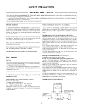
...current check on position, connect one lead of adequate power rating as antennas, terminals, etc., to be sure the set must not exceed 0.75 volt RMS which is the High Voltage Section and the LCD PANEL. Leakage Current Cold Check(Antenna Cold Check) With the instrument AC plug removed from PCB... plug prongs tied together and touch other Hazards. Place the AC switch in the on the exposed metallic parts of the cabinet, such as this TV receiver is returned to prevent X-RADIATION, Shock, Fire, or other ohm-meter lead in parallel with 1000 ohms/volt or more sensitivity. It will ...
...current check on position, connect one lead of adequate power rating as antennas, terminals, etc., to be sure the set must not exceed 0.75 volt RMS which is the High Voltage Section and the LCD PANEL. Leakage Current Cold Check(Antenna Cold Check) With the instrument AC plug removed from PCB... plug prongs tied together and touch other Hazards. Place the AC switch in the on the exposed metallic parts of the cabinet, such as this TV receiver is returned to prevent X-RADIATION, Shock, Fire, or other ohm-meter lead in parallel with 1000 ohms/volt or more sensitivity. It will ...
Service Manual
Page 7
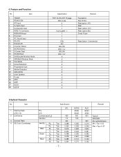
Item 1 Teletext 2 REMOCON 3 AV Input 4 S-Vedio Input 5 Component input 6 PERI TV Connector 7 RGB(VGA)Input 8 H/p input 9 PC Sound input 10 RS-232 11 Discrete IR 12 2 Carrier Stereo 13 NICAM Stereo 14 2 Carrier Dual 15 NICAM ...
Item 1 Teletext 2 REMOCON 3 AV Input 4 S-Vedio Input 5 Component input 6 PERI TV Connector 7 RGB(VGA)Input 8 H/p input 9 PC Sound input 10 RS-232 11 Discrete IR 12 2 Carrier Stereo 13 NICAM Stereo 14 2 Carrier Dual 15 NICAM ...
Service Manual
Page 8
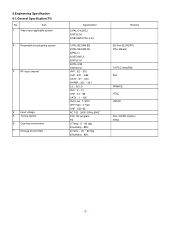
... FVS 100 program FS 1)Temp : 0 ~ 40 deg 2)Humidity : 85% 3)Temp : -20 ~ 60 deg 4)Humidity : 85% Remark EU/Non-EU(RZ/RT) (PAL Market) 7)NTSC Area(RM) PAL FRANCE NTSC JAPAN PAL, 200PR.(Option) NTSC 6.Engineering Specification 6-1.General Specification...
... FVS 100 program FS 1)Temp : 0 ~ 40 deg 2)Humidity : 85% 3)Temp : -20 ~ 60 deg 4)Humidity : 85% Remark EU/Non-EU(RZ/RT) (PAL Market) 7)NTSC Area(RM) PAL FRANCE NTSC JAPAN PAL, 200PR.(Option) NTSC 6.Engineering Specification 6-1.General Specification...
Service Manual
Page 12
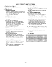
... VOL+ Key at the Auto Gain menu. Or adjust Color Bar signals in accordance with VG819. Once the adjustment is set to the LCD TV. 2. Adjustment 2.1 Adjustment overview The unit is completed, press the Enter Key to save and finish the adjustment 2.2.3 PC Mode adjustment 2.2.3.1 Adjustment... Generator (801GF, VG819) adjust WXGA (1280 X 768) for resolution and Color Bar signals for the pattern. Set the input mode of LCD TV. 2.2.3.2 Auto Gain/Offset adjustment Convert the input mode to D-Sub Jack. ADJUSTMENT INSTRUCTION 1. Press the IN-START Key to the adjustment mode using...
... VOL+ Key at the Auto Gain menu. Or adjust Color Bar signals in accordance with VG819. Once the adjustment is set to the LCD TV. 2. Adjustment 2.1 Adjustment overview The unit is completed, press the Enter Key to save and finish the adjustment 2.2.3 PC Mode adjustment 2.2.3.1 Adjustment... Generator (801GF, VG819) adjust WXGA (1280 X 768) for resolution and Color Bar signals for the pattern. Set the input mode of LCD TV. 2.2.3.2 Auto Gain/Offset adjustment Convert the input mode to D-Sub Jack. ADJUSTMENT INSTRUCTION 1. Press the IN-START Key to the adjustment mode using...
Service Manual
Page 15
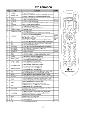
... screen W/B adjustment Exit two times (Adjustment completed) mode. 13 ADJ 14 MPX 15 EXIT 16 APC(PSM) To enter into the adjustment mode. To check TV screen sound easily To select size of the PIP screen in the normal mode 34 POSITION Used as the update key in the teletext mode... the PIP screen 26 PIP INPUT(OP4) To use as a blue key in the PIP screen. To set the delivery condition status after manufacturing the TV set a specific function or complete setting. Used as a hold key in the teletext mode (Page updating is stopped.) 31 TIME Displays the teletext time in...
... screen W/B adjustment Exit two times (Adjustment completed) mode. 13 ADJ 14 MPX 15 EXIT 16 APC(PSM) To enter into the adjustment mode. To check TV screen sound easily To select size of the PIP screen in the normal mode 34 POSITION Used as the update key in the teletext mode... the PIP screen 26 PIP INPUT(OP4) To use as a blue key in the PIP screen. To set the delivery condition status after manufacturing the TV set a specific function or complete setting. Used as a hold key in the teletext mode (Page updating is stopped.) 31 TIME Displays the teletext time in...
Service Manual
Page 19
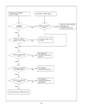
No Raster on AV Signal (Video, S-Video) No Raster on TV(RF) signal Repeat [A] Process Pass Check the output of Fail TU1000 Check 5V, 33V of TU1000 Re-soldering or Fail Change the defect part Check the signal of L1209, L1210, L1212 Fail Change L1209, L1210, L1212 Pass Check the input/output of IC1 Pass Re-soldering or Change the defect part Fail Chek X11 Check the input/output of IC800, IC851 Pass Check the input/output of IC901 Pass Re-soldering or Fail Change the defect part Re-soldering or Change the defect part Fail Check X900 Check input source cable and jack
No Raster on AV Signal (Video, S-Video) No Raster on TV(RF) signal Repeat [A] Process Pass Check the output of Fail TU1000 Check 5V, 33V of TU1000 Re-soldering or Fail Change the defect part Check the signal of L1209, L1210, L1212 Fail Change L1209, L1210, L1212 Pass Check the input/output of IC1 Pass Re-soldering or Change the defect part Fail Chek X11 Check the input/output of IC800, IC851 Pass Check the input/output of IC901 Pass Re-soldering or Fail Change the defect part Re-soldering or Change the defect part Fail Check X900 Check input source cable and jack


