
Service Manual
Page 2
... LG Electronics. LGE Internal Use Only DISASSEMBLY INSTRUCTIONS 2.1 MECHANICAL PARTS 6 2.1.1 FRONT GRILLE 6 2.1.2 CABINET 6 2.1.3 CONTROL BOX 6 2.2 AIR HANDLING PARTS 7 2.2.1 ORIFICE, HEATER ASSY AND TURBO FAN .........7 2.2.2 FAN 7 2.2.3 SHROUD 8 2.3 ELECTRICAL PARTS 8 2.3.1 MOTOR 8 2.3.2 COMPRESSOR 8 2.3.3 CAPACITOR 8 2.3.4 POWER CORD 9 2.3.5 THERMISTOR 9 2.4 REFRIGERATION CYCLE 10 2.4.1 CONDENSER 10 2.4.2 EVAPORATOR 10 2.4.3 CAPILLARY TUBE 10 3. EXPLODED VIEW 20 1. TROUBLESHOOTING GUIDE 3.1 OUTSIDE DIMENSIONS 13 3.2 PIPING SYSTEM 13 3.3 TROUBLESHOOTING GUIDE...
... LG Electronics. LGE Internal Use Only DISASSEMBLY INSTRUCTIONS 2.1 MECHANICAL PARTS 6 2.1.1 FRONT GRILLE 6 2.1.2 CABINET 6 2.1.3 CONTROL BOX 6 2.2 AIR HANDLING PARTS 7 2.2.1 ORIFICE, HEATER ASSY AND TURBO FAN .........7 2.2.2 FAN 7 2.2.3 SHROUD 8 2.3 ELECTRICAL PARTS 8 2.3.1 MOTOR 8 2.3.2 COMPRESSOR 8 2.3.3 CAPACITOR 8 2.3.4 POWER CORD 9 2.3.5 THERMISTOR 9 2.4 REFRIGERATION CYCLE 10 2.4.1 CONDENSER 10 2.4.2 EVAPORATOR 10 2.4.3 CAPILLARY TUBE 10 3. EXPLODED VIEW 20 1. TROUBLESHOOTING GUIDE 3.1 OUTSIDE DIMENSIONS 13 3.2 PIPING SYSTEM 13 3.3 TROUBLESHOOTING GUIDE...

Service Manual
Page 3
... (Btu/h) 8,000 9,800 11,700 INPUT (W) 830 1,110 1,250 RUNNING CURRENT (A) 7.5 10.2 11.4 E.E.R (Btu/w.h) 9.6 8.8 9.4 REFRIGERANT (R-22) CHARGE(g) 540g(19.1OZ) 475g(16.8OZ) 485g(17.1OZ) OPERATING INDOOR (°C) 26.7(DB) 19.4(WB) TEMPERATURE OUTDOOR (°C) 35(DB) 23.9(WB) EVAPORATOR 2 ROW 12STACKS 3 ROW 12STACKS CONDENSER 2 ROW 17STACKS, L-BENDING TYPE FAN, INDOOR TURBO FAN FAN, OUTDOOR PROPELLER TYPE FAN WITH SLINGER-RING FAN SPEEDS, FAN/COOLING 3/3 FAN MOTOR 6 POLES 4POLES OPERATION CONTROL ELECTRIC ROOM TEMP. Inc...
... (Btu/h) 8,000 9,800 11,700 INPUT (W) 830 1,110 1,250 RUNNING CURRENT (A) 7.5 10.2 11.4 E.E.R (Btu/w.h) 9.6 8.8 9.4 REFRIGERANT (R-22) CHARGE(g) 540g(19.1OZ) 475g(16.8OZ) 485g(17.1OZ) OPERATING INDOOR (°C) 26.7(DB) 19.4(WB) TEMPERATURE OUTDOOR (°C) 35(DB) 23.9(WB) EVAPORATOR 2 ROW 12STACKS 3 ROW 12STACKS CONDENSER 2 ROW 17STACKS, L-BENDING TYPE FAN, INDOOR TURBO FAN FAN, OUTDOOR PROPELLER TYPE FAN WITH SLINGER-RING FAN SPEEDS, FAN/COOLING 3/3 FAN MOTOR 6 POLES 4POLES OPERATION CONTROL ELECTRIC ROOM TEMP. Inc...

Service Manual
Page 4
.../32 x 20 3/32 610 x 366 x 499 25 7/8 x 15 17/32 x 16 23/32 656 x 394 x 425 20 1/20 521 REMARK LOUVERED-FIN TYPE OPTIONAL PART Copyright ©2007 LG Electronics. 1.3.2 FOR US10B30A, US12B30A ITEMS MODELS POWER SUPPLY COOLING CAPACITY (Btu/h) INPUT (W) RUNNING CURRENT (A) E.E.R. (Btu/W.h) OPERATING INDOOR (°C) TEMPERA-TURE OUTDOOR (°C) REFRIGERANT (R-22) CHARGE (g) EVAPORATOR CONDENSER FAN, INDOOR FAN, OUTDOOR FAN SPEEDS (FAN/COOLING/HEATING) FAN MOTOR OPERATION CONTROL ROOM TEMP. Inc. All right reserved. LGE Internal Use Only
.../32 x 20 3/32 610 x 366 x 499 25 7/8 x 15 17/32 x 16 23/32 656 x 394 x 425 20 1/20 521 REMARK LOUVERED-FIN TYPE OPTIONAL PART Copyright ©2007 LG Electronics. 1.3.2 FOR US10B30A, US12B30A ITEMS MODELS POWER SUPPLY COOLING CAPACITY (Btu/h) INPUT (W) RUNNING CURRENT (A) E.E.R. (Btu/W.h) OPERATING INDOOR (°C) TEMPERA-TURE OUTDOOR (°C) REFRIGERANT (R-22) CHARGE (g) EVAPORATOR CONDENSER FAN, INDOOR FAN, OUTDOOR FAN SPEEDS (FAN/COOLING/HEATING) FAN MOTOR OPERATION CONTROL ROOM TEMP. Inc. All right reserved. LGE Internal Use Only

Service Manual
Page 5
... room. POWER • To turn the air conditioner OFF, push the button again. LGE Internal Use Only 1.4 FEATURES • Designed for cooling only. • Powerful and quiet cooling. • Top-down chassis for the simple installation and service. • Built in adjustable THERMISTOR and THERMOSTAT. • Washable one-touch filter. • Compact size. 1.5 CONTROL LOCATIONS 1.5.1 COOLING ONLY MODEL • OPERATION REMOTE CONTROL SIGNAL RECEIVER TEMPERATURE SETTING • Use this button to shift mode of operation from COOL ¡ MONEY SAVER ¡ FAN...
... room. POWER • To turn the air conditioner OFF, push the button again. LGE Internal Use Only 1.4 FEATURES • Designed for cooling only. • Powerful and quiet cooling. • Top-down chassis for the simple installation and service. • Built in adjustable THERMISTOR and THERMOSTAT. • Washable one-touch filter. • Compact size. 1.5 CONTROL LOCATIONS 1.5.1 COOLING ONLY MODEL • OPERATION REMOTE CONTROL SIGNAL RECEIVER TEMPERATURE SETTING • Use this button to shift mode of operation from COOL ¡ MONEY SAVER ¡ FAN...

Service Manual
Page 6
... two wire housings in this manual and on pages 29~30 in the control box. 6. Re-install the components by referring to the circuit diagram found on the control box.) Figure 2 Figure 3 Copyright ©2007 LG Electronics. Remove the front grille. (Refer to disassembling the unit, make sure that the POWER is off and the power cord is unplugged from the wall receptacle. 2.1 MECHANICAL PARTS 2.1.1 FRONT GRILLE 1. All...
... two wire housings in this manual and on pages 29~30 in the control box. 6. Re-install the components by referring to the circuit diagram found on the control box.) Figure 2 Figure 3 Copyright ©2007 LG Electronics. Remove the front grille. (Refer to disassembling the unit, make sure that the POWER is off and the power cord is unplugged from the wall receptacle. 2.1 MECHANICAL PARTS 2.1.1 FRONT GRILLE 1. All...
Service Manual
Page 7
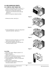
... the fan. 6. Move the condenser sideways carefully. 5. All right reserved. Remove the cabinet. (Refer to section 2.1.1) 2. Re-install the components by referring to the removal procedures, above . Only for training and service purposes -7- 2.2 AIR HANDLING PARTS 2.2.1 ORIFICE, AND TURBO FAN 1. Move the evaporator sideward carefully. 5. Using handheld pliers, remove the clamp which secures the turbo fan. (See Fig. 6) Figure 5 9. Remove the front grille. (Refer...
... the fan. 6. Move the condenser sideways carefully. 5. All right reserved. Remove the cabinet. (Refer to section 2.1.1) 2. Re-install the components by referring to the removal procedures, above . Only for training and service purposes -7- 2.2 AIR HANDLING PARTS 2.2.1 ORIFICE, AND TURBO FAN 1. Move the evaporator sideward carefully. 5. Using handheld pliers, remove the clamp which secures the turbo fan. (See Fig. 6) Figure 5 9. Remove the front grille. (Refer...
Service Manual
Page 8
...) 6. Open the control box 4. All right reserved. Discharge the refrigerant system using a FreonTM Recovery System. Disconnect all the leads on the capacitor terminals. 5. Remove the fan. (Refer to the removal procedures, above . 2.3 ELECTRICAL PARTS 2.3.1 MOTOR 1. Remove the clamp cord and disconnect the wire housing in control box. (Refer to section 2.2.2) 4. Install a valve for training and service purposes -8- Figure 9 Figure 10 Figure 11 Copyright ©2007 LG Electronics. Remove the turbo fan...
...) 6. Open the control box 4. All right reserved. Discharge the refrigerant system using a FreonTM Recovery System. Disconnect all the leads on the capacitor terminals. 5. Remove the fan. (Refer to the removal procedures, above . 2.3 ELECTRICAL PARTS 2.3.1 MOTOR 1. Remove the clamp cord and disconnect the wire housing in control box. (Refer to section 2.2.2) 4. Install a valve for training and service purposes -8- Figure 9 Figure 10 Figure 11 Copyright ©2007 LG Electronics. Remove the turbo fan...
Service Manual
Page 9
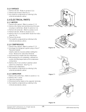
...;2007 LG Electronics. All right reserved. LGE Internal Use Only Remove a screw which fastens the clip cord. 6. Remove the control box. (Refer to section 2.3.3) 3. Figure 13 2.3.5 THERMISTOR 1. Disconnect all the leads of this appliance is damaged, it must be replaced with the factory-authorized and specified cord. 2.3.4 POWER CORD 1. Unfold the control box. (Refer to section 2.1.3) 2. If the supply cord of thermistor terminals. 4. Re-install the...
...;2007 LG Electronics. All right reserved. LGE Internal Use Only Remove a screw which fastens the clip cord. 6. Remove the control box. (Refer to section 2.3.3) 3. Figure 13 2.3.5 THERMISTOR 1. Disconnect all the leads of this appliance is damaged, it must be replaced with the factory-authorized and specified cord. 2.3.4 POWER CORD 1. Unfold the control box. (Refer to section 2.1.3) 2. If the supply cord of thermistor terminals. 4. Re-install the...
Service Manual
Page 10
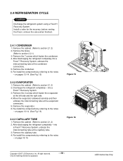
... venting the Freon, remove the valve when finished. 2.4.1 CONDENSER 1. Discharge the refrigerant completely - Move the evaporator sideward carefully and then unbraze the interconnecting tube at the capillary tube. 3. Remove the capillary tube. 4. Figure 15 Figure 16 Copyright ©2007 LG Electronics. Re-install the components by referring to the notes - Re-install the components by referring to section 2.2.1) 3. Remove the condenser. 6. Install...
... venting the Freon, remove the valve when finished. 2.4.1 CONDENSER 1. Discharge the refrigerant completely - Move the evaporator sideward carefully and then unbraze the interconnecting tube at the capillary tube. 3. Remove the capillary tube. 4. Figure 15 Figure 16 Copyright ©2007 LG Electronics. Re-install the components by referring to the notes - Re-install the components by referring to section 2.2.1) 3. Remove the condenser. 6. Install...

Service Manual
Page 11
... replacing refrigeration components, be put in the system. Solder service valves into the vacuum pump. 3) Operate the vacuum pump for a few minutes, then open . 4. Do not add the liquid refrigerant to drop. Use sil-fos solder and solder pinch-off tube ports, leaving the valves open slowly with two full turns counterclockwise and leave the valves closed , stop the vacuum pump. 4) Remove the hose from...
... replacing refrigeration components, be put in the system. Solder service valves into the vacuum pump. 3) Operate the vacuum pump for a few minutes, then open . 4. Do not add the liquid refrigerant to drop. Use sil-fos solder and solder pinch-off tube ports, leaving the valves open slowly with two full turns counterclockwise and leave the valves closed , stop the vacuum pump. 4) Remove the hose from...
Service Manual
Page 12
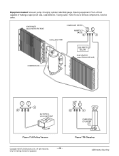
... Internal Use Only Pinch-off tool capable of making a vapor-proof seal, Leak detector, Tubing cutter, Hand Tools to remove components, Service valve. CONDENSER (HIGH PRESSURE SIDE) COMPOUND GAUGE MANIFOLD GAUGE B A CAPILLARY TUBE SEE INSETS BELOW EVAPORATOR (LOW PRESSURE SIDE) COMPRESSOR A B EXTERNAL VACUUM PUMP LOW HI B A CHARGING CYLINDER C Figure 17A-Pulling Vacuum Copyright ©2007 LG Electronics. Equipment needed: Vacuum pump...
... Internal Use Only Pinch-off tool capable of making a vapor-proof seal, Leak detector, Tubing cutter, Hand Tools to remove components, Service valve. CONDENSER (HIGH PRESSURE SIDE) COMPOUND GAUGE MANIFOLD GAUGE B A CAPILLARY TUBE SEE INSETS BELOW EVAPORATOR (LOW PRESSURE SIDE) COMPRESSOR A B EXTERNAL VACUUM PUMP LOW HI B A CHARGING CYLINDER C Figure 17A-Pulling Vacuum Copyright ©2007 LG Electronics. Equipment needed: Vacuum pump...

Service Manual
Page 13
... Internal Use Only ROOM AIR CONDITIONER CYCLE OF REFRIGERATION EVAPORATOR COILS COOLED AIR COMPLETE LIQUID BOIL OFF POINT SUCTION LIME COOL LOW PRESSURE VAPOR ROOM AIR HEAT LOAD CONDENSER COILS VAPOR INLET HOT DISCHARGED AIR MOTOR OUTSIDE COOLING AIR FOR REFRIGERANT PASS THROUGH LIQUID PRESSURE DROP COMPRESSOR OIL (LIQUID REFRIGERANT) CAPILLARY TUBE Figure 18 LIQUID OUTLET HIGH PRESSURE VAPOR LIQUID PEFRIGERANT LOW PRESSURE VAPOR Copyright ©2007 LG Electronics. All right reserved. TROUBLESHOOTING GUIDE 3.1 OUTSIDE DIMENSIONS 20...
... Internal Use Only ROOM AIR CONDITIONER CYCLE OF REFRIGERATION EVAPORATOR COILS COOLED AIR COMPLETE LIQUID BOIL OFF POINT SUCTION LIME COOL LOW PRESSURE VAPOR ROOM AIR HEAT LOAD CONDENSER COILS VAPOR INLET HOT DISCHARGED AIR MOTOR OUTSIDE COOLING AIR FOR REFRIGERANT PASS THROUGH LIQUID PRESSURE DROP COMPRESSOR OIL (LIQUID REFRIGERANT) CAPILLARY TUBE Figure 18 LIQUID OUTLET HIGH PRESSURE VAPOR LIQUID PEFRIGERANT LOW PRESSURE VAPOR Copyright ©2007 LG Electronics. All right reserved. TROUBLESHOOTING GUIDE 3.1 OUTSIDE DIMENSIONS 20...

Service Manual
Page 14
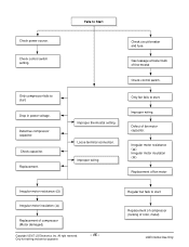
... charge Malfunction of compressor Replacement of fan Clogged air filter Obstruction at air outlet Stop auto air-swing Check outdoor coil (heat exchanger) & the fan operation. Repair gas leak. Correct above troubles Check clogging in the refrigeration circuit and improper application. Repair clogging in two causes. Unit is running but cooling is ineffective Ineffective Cooling Check cold air circulation for training and service purposes - 14 - Dirty indoor coil (Heat exchanger) Malfunction of compressor LGE Internal Use Only 3.3 TROUBLESHOOTING GUIDE In general, possible...
... charge Malfunction of compressor Replacement of fan Clogged air filter Obstruction at air outlet Stop auto air-swing Check outdoor coil (heat exchanger) & the fan operation. Repair gas leak. Correct above troubles Check clogging in the refrigeration circuit and improper application. Repair clogging in two causes. Unit is running but cooling is ineffective Ineffective Cooling Check cold air circulation for training and service purposes - 14 - Dirty indoor coil (Heat exchanger) Malfunction of compressor LGE Internal Use Only 3.3 TROUBLESHOOTING GUIDE In general, possible...
Service Manual
Page 15
Check control switch setting. Check capacitor. Improper wiring Check circuit breaker and fuse. Only fan fails to start . Irregular motor resistance ( ). All right reserved. Improper thermostat setting Loose terminal connection. Irregular motor insulation ( ). Inc. Regular but fails to start Replacement of compressor (locking of compressor (Motor damaged) Copyright ©2007 LG Electronics. Drop in power voltage. Gas leakage at feeler bulb of fan motor capacitor. Only compressor fails to Start Check power source. Only for training and service purposes - ...
Check control switch setting. Check capacitor. Improper wiring Check circuit breaker and fuse. Only fan fails to start . Irregular motor resistance ( ). All right reserved. Improper thermostat setting Loose terminal connection. Irregular motor insulation ( ). Inc. Regular but fails to start Replacement of compressor (locking of compressor (Motor damaged) Copyright ©2007 LG Electronics. Drop in power voltage. Gas leakage at feeler bulb of fan motor capacitor. Only compressor fails to Start Check power source. Only for training and service purposes - ...

Service Manual
Page 16
... if none. If none, check power supply cord. Check switch continuity. Test capacitor. See limits on overload. if worn or missing, replace them. Tighten it . LGE Internal Use Only COMPLAINT Fan motor will not rotate, replace the motor. Refer to wiring diagram for training and service purposes -- 1166-- Realign assembly. If it . If not, replace fan motor. Repair or replace loose terminal. Replace if not within limits, call an...
... if none. If none, check power supply cord. Check switch continuity. Test capacitor. See limits on overload. if worn or missing, replace them. Tighten it . LGE Internal Use Only COMPLAINT Fan motor will not rotate, replace the motor. Refer to wiring diagram for training and service purposes -- 1166-- Realign assembly. If it . If not, replace fan motor. Repair or replace loose terminal. Replace if not within limits, call an...
Service Manual
Page 17
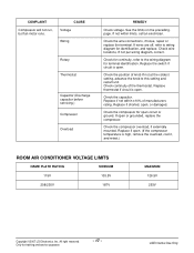
... reserved. Check for continuity, refer to wiring diagram for terminal identification. Replace if shorted, open . (If the compressor temperature is high, remove the overload, cool it, and retest.) ROOM AIR CONDITIONER VOLTAGE LIMITS NAME PLATE RATING MINIMUM 115V 103.5V 208/230V 187V MAXIMUM 126.5V 253V Copyright ©2007 LG Electronics. LGE Internal Use Only Check wire locations. Replace thermostat if circuit is open . Replace if not within limits, call an...
... reserved. Check for continuity, refer to wiring diagram for terminal identification. Replace if shorted, open . (If the compressor temperature is high, remove the overload, cool it, and retest.) ROOM AIR CONDITIONER VOLTAGE LIMITS NAME PLATE RATING MINIMUM 115V 103.5V 208/230V 187V MAXIMUM 126.5V 253V Copyright ©2007 LG Electronics. LGE Internal Use Only Check wire locations. Replace thermostat if circuit is open . Replace if not within limits, call an...

Service Manual
Page 18
... properly sized for the area to be cooled. if restricted, clean carefully (do not damage fins). Inc. Close if open . (If the compressor temperature is hitting air guide, rearrange the air handling parts. Condenser fins (damaged) Capacitor Wiring Refrigerating system Air filter Exhaust damper door Unit undersized Blower or fan Copper tubing REMEDY Check the voltage. If loose, repair or replace. LGE Internal Use Only Clean the interior base before reassembling. Check the set...
... properly sized for the area to be cooled. if restricted, clean carefully (do not damage fins). Inc. Close if open . (If the compressor temperature is hitting air guide, rearrange the air handling parts. Condenser fins (damaged) Capacitor Wiring Refrigerating system Air filter Exhaust damper door Unit undersized Blower or fan Copper tubing REMEDY Check the voltage. If loose, repair or replace. LGE Internal Use Only Clean the interior base before reassembling. Check the set...

Service Manual
Page 19
... Internal Use Only Inc. DESCRIPTION 264110 POWER CORD 346811 FAN MOTOR W0CZZ CAPACITOR 554160 COMPRESSOR 567502 OVERLOAD PROTECTOR US08B10A 67300012 67303021 67300710 67301628 67301406 US10B10A 67300012 67303022 67300717 67301619 67301409 PART NO. US12B10A 67300013 67303023 67300717 67301626 67301407 US10B30A 67300015 67303024 67300708 67301627 67301413 US12B30A Q'TY PER SET REMARKS 67300015 1 67303025 1 67300708 1 67301629 1 67500056 1 Copyright ©2007 LG Electronics. SCHEMATIC DIAGRAM 4.1 CIRCUIT DIAGRAM • MODEL : US08B10A...
... Internal Use Only Inc. DESCRIPTION 264110 POWER CORD 346811 FAN MOTOR W0CZZ CAPACITOR 554160 COMPRESSOR 567502 OVERLOAD PROTECTOR US08B10A 67300012 67303021 67300710 67301628 67301406 US10B10A 67300012 67303022 67300717 67301619 67301409 PART NO. US12B10A 67300013 67303023 67300717 67301626 67301407 US10B30A 67300015 67303024 67300708 67301627 67301413 US12B30A Q'TY PER SET REMARKS 67300015 1 67303025 1 67300708 1 67301629 1 67500056 1 Copyright ©2007 LG Electronics. SCHEMATIC DIAGRAM 4.1 CIRCUIT DIAGRAM • MODEL : US08B10A...

Service Manual
Page 20
Inc. 5. All right reserved. EXPLODED VIEW • MODEL: US10B10A, US12B10A, US12B30A E 152302 135303 147581 147582A 132100 147582B E 559011 354210 349480 346811 352380 149980 131400 W48602 359012 435300A 435300 435301 554031 349600 147900 130410 A W6631 264110 268711A B 567480 C 352115 268711B 35211A W0CZZ 554160 238310 237200 267110 Copyright ©2007 LG Electronics. Only for training and service purposes 352113 552113 - 20 - 550140 LGE Internal Use Only
Inc. 5. All right reserved. EXPLODED VIEW • MODEL: US10B10A, US12B10A, US12B30A E 152302 135303 147581 147582A 132100 147582B E 559011 354210 349480 346811 352380 149980 131400 W48602 359012 435300A 435300 435301 554031 349600 147900 130410 A W6631 264110 268711A B 567480 C 352115 268711B 35211A W0CZZ 554160 238310 237200 267110 Copyright ©2007 LG Electronics. Only for training and service purposes 352113 552113 - 20 - 550140 LGE Internal Use Only

Service Manual
Page 21
B 554160 550140 LGE Internal Use Only All right reserved. • MODEL: US08B10A / US10B30A E 152302 135303 147581 147582A 132100 E 559011 354210 349480 147582B 346811 352380 149980 131400 W48602 359012 435300A 435300 435301 554031 A W6631 268711A 567480 268711B 264110 147900 130410 C 352115 35211A W0CZZ 238310 237200 267110 Copyright ©2007 LG Electronics. Inc. Only for training and service purposes 352113 552113 - 21 -
B 554160 550140 LGE Internal Use Only All right reserved. • MODEL: US08B10A / US10B30A E 152302 135303 147581 147582A 132100 E 559011 354210 349480 147582B 346811 352380 149980 131400 W48602 359012 435300A 435300 435301 554031 A W6631 268711A 567480 268711B 264110 147900 130410 C 352115 35211A W0CZZ 238310 237200 267110 Copyright ©2007 LG Electronics. Inc. Only for training and service purposes 352113 552113 - 21 -


