Service Manual
Page 1
website http://www.lgservice.com LG LG Room Air Conditioner SERVICE MANUAL MODEL: ACQ058PL KG5200ER LW5200ER WG5200ER WG6000R KG6000R M5404R WG5200R M6004R HBLG6000R HBLG5200E ACQ052PK LW7000R WM-5031 LW050CE LWJ0515PAG LW5200R CAUTION • BEFORE SERVICING THE UNIT, READ THE SAFETY PRECAUTIONS IN THIS MANUAL. • ONLY FOR AUTHORIZED SERVICE PERSONNEL.
website http://www.lgservice.com LG LG Room Air Conditioner SERVICE MANUAL MODEL: ACQ058PL KG5200ER LW5200ER WG5200ER WG6000R KG6000R M5404R WG5200R M6004R HBLG6000R HBLG5200E ACQ052PK LW7000R WM-5031 LW050CE LWJ0515PAG LW5200R CAUTION • BEFORE SERVICING THE UNIT, READ THE SAFETY PRECAUTIONS IN THIS MANUAL. • ONLY FOR AUTHORIZED SERVICE PERSONNEL.

Service Manual
Page 2
... 5.4 COMPONENTS LOCATION(FOR DISPLAY P.W.B ASM) ...28 6. SPECIFICATION AND PARTS LIST ...30 -2- DISASSEMBLY INSTRUCTIONS ...6 2.1 MECHANICAL PARTS ...6 2.1.1 FRONT GRILLE ...6 2.1.2 CABINET...6 2.1.3 CONTROL BOARD ...6 2.2 AIR HANDLING PARTS ...7 2.2.1 AIR GUIDE UPPER...7 2.2.2 ORIFICE, TURBO FAN AND FAN...7 2.2.3 MOTOR ...8 2.2.4 AIR GUIDE ...8 2.3 ELECTRICAL PARTS ...8 2.3.1 OVERLOAD PROTECTOR ...8 2.3.2 COMPRESSOR ...9 2.3.3 CAPACITOR ...9 2.3.4 THERMISTOR...9 2.3.5 CONTROL PANEL...9 2.3.6 POWER CORD ...10 2.4 REFRIGERANT CYCLE ...10 2.4.1 CONDENSER ...10 2.4.2 EVAPORATOR ...10...
... 5.4 COMPONENTS LOCATION(FOR DISPLAY P.W.B ASM) ...28 6. SPECIFICATION AND PARTS LIST ...30 -2- DISASSEMBLY INSTRUCTIONS ...6 2.1 MECHANICAL PARTS ...6 2.1.1 FRONT GRILLE ...6 2.1.2 CABINET...6 2.1.3 CONTROL BOARD ...6 2.2 AIR HANDLING PARTS ...7 2.2.1 AIR GUIDE UPPER...7 2.2.2 ORIFICE, TURBO FAN AND FAN...7 2.2.3 MOTOR ...8 2.2.4 AIR GUIDE ...8 2.3 ELECTRICAL PARTS ...8 2.3.1 OVERLOAD PROTECTOR ...8 2.3.2 COMPRESSOR ...9 2.3.3 CAPACITOR ...9 2.3.4 THERMISTOR...9 2.3.5 CONTROL PANEL...9 2.3.6 POWER CORD ...10 2.4 REFRIGERANT CYCLE ...10 2.4.1 CONDENSER ...10 2.4.2 EVAPORATOR ...10...
Service Manual
Page 3
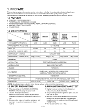
... FOR THE SIMPLE INSTALLATION AND SERVICE • WASHABLE ONE-TOUCH FILTER • COMPACT SIZE 1.2 SPECIFICATIONS MODELS ITEMS WG5200ER, LW5200ER, HBLG5200E, LWC051JGMK2 KG5200ER ACQ058PL COOLING CAPACITY (BTU/h) 5,200 LW050CE 5,050 WG5200R ACQ052PK M5404R WM5031 LWJ0515PAG LW5200R 5,250 WG6000R ... CHARGE (R-22) 330g (11.6 Oz) CAPILLARY TUBE 220g(7.8 Oz) 235g (8.3 Oz) 315g (11.1 Oz) INSIDE FAN TURBO OUTSIDE FAN AIR DISCHARGE PROPELLER FAN WITH SLINGER RING 2-WAY (RIGHT AND LEFT) CHASSIS TOP-DOWN PROTECTOR • OVERLOAD PROTECTOR FOR COMPRESSOR • INTERNAL PROTECTOR...
... FOR THE SIMPLE INSTALLATION AND SERVICE • WASHABLE ONE-TOUCH FILTER • COMPACT SIZE 1.2 SPECIFICATIONS MODELS ITEMS WG5200ER, LW5200ER, HBLG5200E, LWC051JGMK2 KG5200ER ACQ058PL COOLING CAPACITY (BTU/h) 5,200 LW050CE 5,050 WG5200R ACQ052PK M5404R WM5031 LWJ0515PAG LW5200R 5,250 WG6000R ... CHARGE (R-22) 330g (11.6 Oz) CAPILLARY TUBE 220g(7.8 Oz) 235g (8.3 Oz) 315g (11.1 Oz) INSIDE FAN TURBO OUTSIDE FAN AIR DISCHARGE PROPELLER FAN WITH SLINGER RING 2-WAY (RIGHT AND LEFT) CHASSIS TOP-DOWN PROTECTOR • OVERLOAD PROTECTOR FOR COMPRESSOR • INTERNAL PROTECTOR...

Service Manual
Page 4
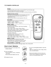
ENERGY SAVER The fan stops when the compressor stops cooling. • Approximately every 3 minutes the fan will turn on and check the room air to 86°F(30°C) by 1°F(1°C). To turn the unit OFF, push the button again. • This button takes priority over any other ...
ENERGY SAVER The fan stops when the compressor stops cooling. • Approximately every 3 minutes the fan will turn on and check the room air to 86°F(30°C) by 1°F(1°C). To turn the unit OFF, push the button again. • This button takes priority over any other ...
Service Manual
Page 5
...Low(F1) High(F2) or {High(F3) Mid(F2) Low(F1) High(F3)...} ON/OFF TIMER - Remove the cover from the remote controller if the air conditioner is set within a range of the room. Select the lower number for an extended length of time. -5- Power FAN SPEED • Everytime you first... Set ON, push the button. Temp Fan Speed Timer Mode Energy Auto Saver Swing How to determine if cooling is on and check the room air to Insert Batteries 1. TEMPERATURE SETTING • This button can be used for lower temperature of the remote controller 2. Re-attach the cover. • Do ...
...Low(F1) High(F2) or {High(F3) Mid(F2) Low(F1) High(F3)...} ON/OFF TIMER - Remove the cover from the remote controller if the air conditioner is set within a range of the room. Select the lower number for an extended length of time. -5- Power FAN SPEED • Everytime you first... Set ON, push the button. Temp Fan Speed Timer Mode Energy Auto Saver Swing How to determine if cooling is on and check the room air to Insert Batteries 1. TEMPERATURE SETTING • This button can be used for lower temperature of the remote controller 2. Re-attach the cover. • Do ...

Service Manual
Page 6
... by placing the tabs in this manual or inside control board.) Figure 3 Figure 4 Figure 5 -6- Remove 2 screws that secures the front grille to base pan and air guide. (See Figure 4) 5. See step 2.3.3 on page 26 in the slots and push the grille until it snaps into place. Disconnect one housing terminal and...
... by placing the tabs in this manual or inside control board.) Figure 3 Figure 4 Figure 5 -6- Remove 2 screws that secures the front grille to base pan and air guide. (See Figure 4) 5. See step 2.3.3 on page 26 in the slots and push the grille until it snaps into place. Disconnect one housing terminal and...

Service Manual
Page 7
...6 Figure 7 2.2.2 ORIFICE, TURBO FAN AND FAN 1. Remove the front grille. (Refer to remove it from the condenser. 9. Press the snap area of the air guide blower. (See Figure 8) 11. This allows you to Section 2.1.1) 3. Remove the clamp springs which are clamped to Section 2.1.2) 4. Remove the shroud. 14....the evaporator and condenser. (See Figure 7) 10. Disconnect the unit from the power source. 2. Remove 2 screws that secure the air guide upper to condenser. (See Figure 7) 7. Lift the compressor upward with your thumbs. Remove 2 screws that secure the base pan to...
...6 Figure 7 2.2.2 ORIFICE, TURBO FAN AND FAN 1. Remove the front grille. (Refer to remove it from the condenser. 9. Press the snap area of the air guide blower. (See Figure 8) 11. This allows you to Section 2.1.1) 3. Remove the clamp springs which are clamped to Section 2.1.2) 4. Remove the shroud. 14....the evaporator and condenser. (See Figure 7) 10. Disconnect the unit from the power source. 2. Remove 2 screws that secure the air guide upper to condenser. (See Figure 7) 7. Lift the compressor upward with your thumbs. Remove 2 screws that secure the base pan to...

Service Manual
Page 8
... base pan. (See Figure 11) 9. Remove the compressor, turbo fan, fan and shroud. (Refer to Section 2.2.1) 6. Remove the air guide upper. (Refer to Section 2.2.2) 7. Remove the cabinet. (Refer to Section 2.2.1) 6. Remove the overload protector. 6. Figure 13 ...Disconnect the unit from the power source. 2. Remove the air guide upper. (Refer to Section 2.1.2) 4. Figure 10 2.2.4 AIR GUIDE 1. Disconnect the unit from the power source. 2. Remove the front grille and cabinet. (Refer to ...
... base pan. (See Figure 11) 9. Remove the compressor, turbo fan, fan and shroud. (Refer to Section 2.2.1) 6. Remove the air guide upper. (Refer to Section 2.2.2) 7. Remove the cabinet. (Refer to Section 2.2.1) 6. Remove the overload protector. 6. Figure 13 ...Disconnect the unit from the power source. 2. Remove the air guide upper. (Refer to Section 2.1.2) 4. Figure 10 2.2.4 AIR GUIDE 1. Disconnect the unit from the power source. 2. Remove the front grille and cabinet. (Refer to ...

Service Manual
Page 10
...-install by referring to Section 2.1.1) 3. Discharge the refrigerant by using a refrigerant recovery system. 3. Remove 2 screws that secure control board to base pan and air guide. (Refer to Section 2.1.2) 2. Remove the cabinet. (Refer to Section 2.1.3) 5. Discharge the refrigerant by using a refrigerant recovery system. 3. After discharging...unit from source of power. 2. Re-install by referring to the control board. 8. Remove the condenser. 6. Remove the air guide upper. (Refer to procedures above . -10- Pull the power cord. 9. 2.3.6 POWER CORD 1. Remove the evaporator. 6.
...-install by referring to Section 2.1.1) 3. Discharge the refrigerant by using a refrigerant recovery system. 3. Remove 2 screws that secure control board to base pan and air guide. (Refer to Section 2.1.2) 2. Remove the cabinet. (Refer to Section 2.1.3) 5. Discharge the refrigerant by using a refrigerant recovery system. 3. After discharging...unit from source of power. 2. Re-install by referring to the control board. 8. Remove the condenser. 6. Remove the air guide upper. (Refer to procedures above . -10- Pull the power cord. 9. 2.3.6 POWER CORD 1. Remove the evaporator. 6.

Service Manual
Page 11
... cutter, cut the pinch-off tube about 2 inches from the vacuum pump and place it . Discharge the refrigerant by using a refrigerant recovery system. 3. Remove the air guide upper. (Refer to Section 2.1.2) 2. Recharge as shown in place on the charging cylinder. CAUTION : If high vacuum equipment is required, the high-side will...
... cutter, cut the pinch-off tube about 2 inches from the vacuum pump and place it . Discharge the refrigerant by using a refrigerant recovery system. 3. Remove the air guide upper. (Refer to Section 2.1.2) 2. Recharge as shown in place on the charging cylinder. CAUTION : If high vacuum equipment is required, the high-side will...
Service Manual
Page 13
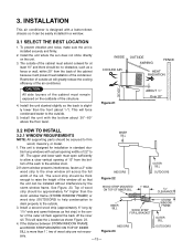
... cabinet because it can be thick enough to the outside . 3. Install the unit with actual opening of 13" from the back of the air conditioner. The upper and lower sash must open sufficiently to the outside . 5. Top of wood strip should be approximately 3/4" higher than the...WOOD STRIP FOR L BRACKET INDOORS Figure 23 STORM WINDOW FRAME OUTER SILL OUTDOORS sary. -13- CAUTION All side louvers of 22" to 36". INSIDE COOLED AIR OUTSIDE AWNING FENCE HEAT RADIATION 30"-60" Figure 21 ABOUT / 1 4 " Over 20" 3.2 HOW TO INSTALL 3.2.1 WINDOW REQUIREMENTS INNER SILL NOTE: ...
... cabinet because it can be thick enough to the outside . 3. Install the unit with actual opening of 13" from the back of the air conditioner. The upper and lower sash must open sufficiently to the outside . 5. Top of wood strip should be approximately 3/4" higher than the...WOOD STRIP FOR L BRACKET INDOORS Figure 23 STORM WINDOW FRAME OUTER SILL OUTDOORS sary. -13- CAUTION All side louvers of 22" to 36". INSIDE COOLED AIR OUTSIDE AWNING FENCE HEAT RADIATION 30"-60" Figure 21 ABOUT / 1 4 " Over 20" 3.2 HOW TO INSTALL 3.2.1 WINDOW REQUIREMENTS INNER SILL NOTE: ...
Service Manual
Page 14
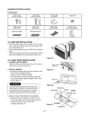
... seal strip and attach the seal strip to the unit with the short side of the inner sill, as shown in place. Carefully lift the air conditioner and slide it into the guides of the bottom window. (Figure. 25) 3.2.3 NOW START INSTALLATION 1. See Figure. 27. Insert the guide panels into... the open window. Use the 2 screws (TYPE A) provided. b. Make sure the bottom guide of the air conditioner drops into the notches of inner sill. LOCATING UNIT IN WINDOW Open the window and mark center line on the center of bracket as...
... seal strip and attach the seal strip to the unit with the short side of the inner sill, as shown in place. Carefully lift the air conditioner and slide it into the guides of the bottom window. (Figure. 25) 3.2.3 NOW START INSTALLATION 1. See Figure. 27. Insert the guide panels into... the open window. Use the 2 screws (TYPE A) provided. b. Make sure the bottom guide of the air conditioner drops into the notches of inner sill. LOCATING UNIT IN WINDOW Open the window and mark center line on the center of bracket as...
Service Manual
Page 15
...secure them, as shown in Figure. 29. 4. SECURE THE GUIDE PANELS Extend the guide panels (TYPE F) to the rear hole of room air conditioner is now completed. Figure 28 CENTER LINE WINDOW FRAME UPPER GUIDE SEAL BOTTOM GUIDE ABOUT 1/4" 5. Remove the screws that secure the cabinet and... A) screw, as shown Figure. 31. 7. Figure 32 DRAIN CAP DRAIN PIPE -15- b. Stuff the sash seal between the glass and the window to prevent air and insects from the fins to overflow. Figure 29 L BRACKET L BRACKET TYPE A TYPE B SASH SEAL (TYPE E) Figure 30 TYPE B Figure 31 Support Bracket...
...secure them, as shown in Figure. 29. 4. SECURE THE GUIDE PANELS Extend the guide panels (TYPE F) to the rear hole of room air conditioner is now completed. Figure 28 CENTER LINE WINDOW FRAME UPPER GUIDE SEAL BOTTOM GUIDE ABOUT 1/4" 5. Remove the screws that secure the cabinet and... A) screw, as shown Figure. 31. 7. Figure 32 DRAIN CAP DRAIN PIPE -15- b. Stuff the sash seal between the glass and the window to prevent air and insects from the fins to overflow. Figure 29 L BRACKET L BRACKET TYPE A TYPE B SASH SEAL (TYPE E) Figure 30 TYPE B Figure 31 Support Bracket...
Service Manual
Page 16
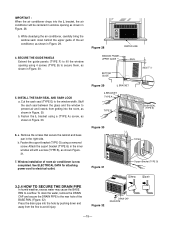
...However, if you wish to use an extension cord, use of the guide panels, and save for reinstallation later. REMOVAL FROM WINDOW Turn the air conditioner off, disconnect the power cord, remove the L bracket, the screws and support bracket installed through the top and bottom of an extension cord.... Lift the air conditioner from the window and remove the sash seal from between the windows. 3.3 ELECTRICAL DATA Line Cord Plug Use Wall Receptacle Power Supply Do ...
...However, if you wish to use an extension cord, use of the guide panels, and save for reinstallation later. REMOVAL FROM WINDOW Turn the air conditioner off, disconnect the power cord, remove the L bracket, the screws and support bracket installed through the top and bottom of an extension cord.... Lift the air conditioner from the window and remove the sash seal from between the windows. 3.3 ELECTRICAL DATA Line Cord Plug Use Wall Receptacle Power Supply Do ...
Service Manual
Page 17
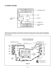
... LIQUID BOIL OFF POINT SUCTION LINE COOL LOW PRESSURE VAPOR ROOM AIR HEAT LOAD CONDENSER COILS VAPOR INLET HOT DISCHARGED AIR OUTSIDE COOLING AIR FOR REFRIGERANT PASS THROUGH LIQUID PRESSURE DROP MOTOR COMPRESSOR DISCHARGE LINE NOT HIGH PRESSURE VAPOR OIL (LIQUID REFRIGERANT) CAPILLARY TUBE Figure 33 LIQUID OUTLET HIGH ...
... LIQUID BOIL OFF POINT SUCTION LINE COOL LOW PRESSURE VAPOR ROOM AIR HEAT LOAD CONDENSER COILS VAPOR INLET HOT DISCHARGED AIR OUTSIDE COOLING AIR FOR REFRIGERANT PASS THROUGH LIQUID PRESSURE DROP MOTOR COMPRESSOR DISCHARGE LINE NOT HIGH PRESSURE VAPOR OIL (LIQUID REFRIGERANT) CAPILLARY TUBE Figure 33 LIQUID OUTLET HIGH ...
Service Manual
Page 18
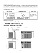
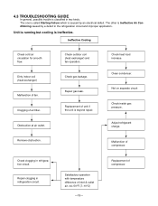
...is caused by a defect in two kinds. Repair gas leak. Ineffective Cooling Check cold air circulation for smooth flow. Obstruction at air outlet. Replacement of inlet & outlet air; 44~50°F (7~10°C) -18- Check clogging in refrigeration circuit. Replacement of.... The other is classified in the refrigeration circuit and improper application. 4.3 TROUBLESHOOTING GUIDE In general, possible trouble is Ineffective Air Conditioning caused by an electrical defect. Dirty indoor coil (heat exchanger) Malfunction of compressor. Clogging of compressor. Check outdoor ...
...is caused by a defect in two kinds. Repair gas leak. Ineffective Cooling Check cold air circulation for smooth flow. Obstruction at air outlet. Replacement of inlet & outlet air; 44~50°F (7~10°C) -18- Check clogging in refrigeration circuit. Replacement of.... The other is classified in the refrigeration circuit and improper application. 4.3 TROUBLESHOOTING GUIDE In general, possible trouble is Ineffective Air Conditioning caused by an electrical defect. Dirty indoor coil (heat exchanger) Malfunction of compressor. Clogging of compressor. Check outdoor ...
Service Manual
Page 23
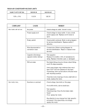
... terminal. Fan blade hitting shroud or blower wheel hitting scroll. See limits on overload REMEDY Check voltage at outlet. If not, replace fan motor. ROOM AIR CONDITIONER VOLTAGE LIMITS NAME PLATE RATING MINIMUM 115V ± 10% 103.5V MAXIMUM 126.5V COMPLAINT Fan motor will not rotate, replace the motor. Correct...
... terminal. Fan blade hitting shroud or blower wheel hitting scroll. See limits on overload REMEDY Check voltage at outlet. If not, replace fan motor. ROOM AIR CONDITIONER VOLTAGE LIMITS NAME PLATE RATING MINIMUM 115V ± 10% 103.5V MAXIMUM 126.5V COMPLAINT Fan motor will not rotate, replace the motor. Correct...

Service Manual
Page 25
...area to be cooled. Remove the cabinet and carefully rearrange the tubing not to cycle. Condenser fins (damaged) Capacitor Wiring Refrigeration system Air filter Unit undersized Blower or fan Copper tubing REMEDY If not running, determine the cause. If the condenser fins are closed over a... large area on overload CAUSE Fan motor Condenser air flow restriction Insufficient cooling. Straighten the fins or replace the coil. If restricted, clean carefully with a vacuum cleaner (do not damage fins...
...area to be cooled. Remove the cabinet and carefully rearrange the tubing not to cycle. Condenser fins (damaged) Capacitor Wiring Refrigeration system Air filter Unit undersized Blower or fan Copper tubing REMEDY If not running, determine the cause. If the condenser fins are closed over a... large area on overload CAUSE Fan motor Condenser air flow restriction Insufficient cooling. Straighten the fins or replace the coil. If restricted, clean carefully with a vacuum cleaner (do not damage fins...

Service Manual
Page 27
... RY-MED RY-HI R12F 20K 5V CN-WOR C01J 0.1/275V R01J 120 1/2W R02E 20 R01E 1K ZNR01J SVC271D-14A RY-COMP G4A-1A-E-LG FUSE 250V/T2A POWER TRANS 1 7 D02D D05D 2 D03D 4 D04D + C01D D02D~D05D 1000 1N4004 35V 12V IC01D O I 7812 + C02D C03D 0.1 1000 50V 16V IC02D O I 7805... 220 R07G 220 6 7 8 9 10 11 12 15 16 CN-DISP 1 17 5 4 12 TEMP UP SW7 D07F ENERGY SAVER SW3 D03F 5V 11 A/SWING 10 A/RESTART 9 8 7 AIR PURIFIER 6 3 2 CN-DISP TEMP DOWN SW5 D05F TIMER SW2 D02F COOL DEFROST DRY/HEAT TIMER FAN E/SAVER BZ01E PKM13EPY -4002 MODE SW4 D04F FAN SW1...
... RY-MED RY-HI R12F 20K 5V CN-WOR C01J 0.1/275V R01J 120 1/2W R02E 20 R01E 1K ZNR01J SVC271D-14A RY-COMP G4A-1A-E-LG FUSE 250V/T2A POWER TRANS 1 7 D02D D05D 2 D03D 4 D04D + C01D D02D~D05D 1000 1N4004 35V 12V IC01D O I 7812 + C02D C03D 0.1 1000 50V 16V IC02D O I 7805... 220 R07G 220 6 7 8 9 10 11 12 15 16 CN-DISP 1 17 5 4 12 TEMP UP SW7 D07F ENERGY SAVER SW3 D03F 5V 11 A/SWING 10 A/RESTART 9 8 7 AIR PURIFIER 6 3 2 CN-DISP TEMP DOWN SW5 D05F TIMER SW2 D02F COOL DEFROST DRY/HEAT TIMER FAN E/SAVER BZ01E PKM13EPY -4002 MODE SW4 D04F FAN SW1...
Service Manual
Page 30
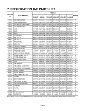
..., EVAPORATOR IN 5211A10063A 5211A10063A 5211A10063C 5211A10063C 5211A10063A 5211A10063C R 35211A TUBE ASSEMBLY, SUCTION SINGLE 5211A10062A 5211A10062A 5211A10062B 5211A10062B 5211A10062A 5211A10062B R 352390-1 AIR GUIDE ASSEMBLY 5239A30003A 5239A30003A 5239A30003A 5239A30003A 5239A30003A 5239A30003A R 352390-2 AIR GUIDE ASSEMBLY 5239A10005A 5239A10005A 5239A10005B 5239A10005B 5239A10005A 5239A10005B R 352410 EVAPORATOR ASSEMBLY, FIRST 5421A10008B 5421A10008B 5421A20016G 5421A20016G 5421A10008B 5421A20016G R 359012 FAN, TURBO...
..., EVAPORATOR IN 5211A10063A 5211A10063A 5211A10063C 5211A10063C 5211A10063A 5211A10063C R 35211A TUBE ASSEMBLY, SUCTION SINGLE 5211A10062A 5211A10062A 5211A10062B 5211A10062B 5211A10062A 5211A10062B R 352390-1 AIR GUIDE ASSEMBLY 5239A30003A 5239A30003A 5239A30003A 5239A30003A 5239A30003A 5239A30003A R 352390-2 AIR GUIDE ASSEMBLY 5239A10005A 5239A10005A 5239A10005B 5239A10005B 5239A10005A 5239A10005B R 352410 EVAPORATOR ASSEMBLY, FIRST 5421A10008B 5421A10008B 5421A20016G 5421A20016G 5421A10008B 5421A20016G R 359012 FAN, TURBO...


