
Owners Manual
Page 3
...the service center or a professional installation agency. • Otherwise, it may cause electrical shock. Securely attach the electrical part cover to the indoor unit and the service panel to dust, water, etc. Downloaded from www.Manualslib.com manuals search engine Owner's Manual 3 Be sure to ignoring ...The meanings of the symbols used in a fire or electric shock due to the outdoor unit. • If the electrical part cover of the indoor unit and the service panel of the outdoor unit are as shown below. This symbol indicates the possibility of injury or damage to do. ...
...the service center or a professional installation agency. • Otherwise, it may cause electrical shock. Securely attach the electrical part cover to the indoor unit and the service panel to dust, water, etc. Downloaded from www.Manualslib.com manuals search engine Owner's Manual 3 Be sure to ignoring ...The meanings of the symbols used in a fire or electric shock due to the outdoor unit. • If the electrical part cover of the indoor unit and the service panel of the outdoor unit are as shown below. This symbol indicates the possibility of injury or damage to do. ...

Owners Manual
Page 22
...or clogged coils will reduce the Air intake (Side) operating efficiency of detergent in the shade. Outdoor Unit The heat exchanger coils and panel vents of the outdoor unit should be checked and cleaned once every 2 weeks or more ) is conspicuous, wash with a solution ... if neccessary. 1. Lift the front panel. Re-install the air filter. Maintenance and Service Maintenance and Service Indoor Unit WARNING: Turn the system off before cleaning the indoor unit. Could cause deformation and/or discoloration. • Volatile substances Could damage the surfaces of the followings: •...
...or clogged coils will reduce the Air intake (Side) operating efficiency of detergent in the shade. Outdoor Unit The heat exchanger coils and panel vents of the outdoor unit should be checked and cleaned once every 2 weeks or more ) is conspicuous, wash with a solution ... if neccessary. 1. Lift the front panel. Re-install the air filter. Maintenance and Service Maintenance and Service Indoor Unit WARNING: Turn the system off before cleaning the indoor unit. Could cause deformation and/or discoloration. • Volatile substances Could damage the surfaces of the followings: •...

Service Manual
Page 2
Contents Details of 2003 LG Model Name 3 Functions ...4 Product References ...6 Dimensions ...7 Refrigeration Cycle Diagram 9 Wiring Diagram...10 Operation Details ...11 Display Function ...17 Self-diagnosis Function...17 Installation ...18 Operation ...33 Disassembly of the parts (Indoor Unit 33 2-way, 3-way Valve...35 Cycle Troubleshooting Guide 42 Electronic Control Device...52 Schematic Diagram ...55 Exploded View and Replacement Parts List 57 -2-
Contents Details of 2003 LG Model Name 3 Functions ...4 Product References ...6 Dimensions ...7 Refrigeration Cycle Diagram 9 Wiring Diagram...10 Operation Details ...11 Display Function ...17 Self-diagnosis Function...17 Installation ...18 Operation ...33 Disassembly of the parts (Indoor Unit 33 2-way, 3-way Valve...35 Cycle Troubleshooting Guide 42 Electronic Control Device...52 Schematic Diagram ...55 Exploded View and Replacement Parts List 57 -2-
Service Manual
Page 4
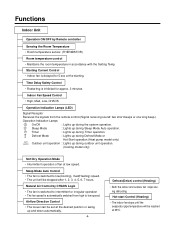
... : Lights up during outdoor unit operation. (Cooling model only) Soft Dry Operation Mode • Intermittent operation of fan at the desired position or swing up and down automatically. -4- Indoor Fan Speed Control • High, Med, Low, CHAOS Operation indication Lamps (LED) Signal Receptor ...Receives the signals from high to low speed. Timer : Lights up during Sleep Mode Auto operation. Functions Indoor Unit Operation ON/OFF by CHAOS Logic • The fan is switched to intermittent or irregular operation • The fan speed is ...
... : Lights up during outdoor unit operation. (Cooling model only) Soft Dry Operation Mode • Intermittent operation of fan at the desired position or swing up and down automatically. -4- Indoor Fan Speed Control • High, Med, Low, CHAOS Operation indication Lamps (LED) Signal Receptor ...Receives the signals from high to low speed. Timer : Lights up during Sleep Mode Auto operation. Functions Indoor Unit Operation ON/OFF by CHAOS Logic • The fan is switched to intermittent or irregular operation • The fan speed is ...

Service Manual
Page 9
Refrigeration Cycle Diagram • Cooling Only Models INDOOR UNIT OUTDOOR UNIT LIQUID SIDE CAPILLARY TUBE HEAT EXCHANGER (EVAPORATOR) GAS SIDE HEAT EXCHANGER (CONDENSER) COMPRESSOR MODEL 9K, 12K (Cooling Only) Pipe size(Diameter:ø) Gas Liquid 1/2" 1/4" Piping ...
Refrigeration Cycle Diagram • Cooling Only Models INDOOR UNIT OUTDOOR UNIT LIQUID SIDE CAPILLARY TUBE HEAT EXCHANGER (EVAPORATOR) GAS SIDE HEAT EXCHANGER (CONDENSER) COMPRESSOR MODEL 9K, 12K (Cooling Only) Pipe size(Diameter:ø) Gas Liquid 1/2" 1/4" Piping ...
Service Manual
Page 10
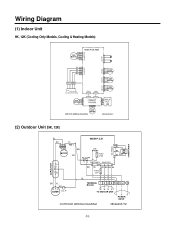
Wiring Diagram (1) Indoor Unit 9K, 12K (Cooling Only Models, Cooling & Heating Models) CAPACITOR C F CN-TRANS TRANSFORMER (2) Outdoor Unit (9K, 12K) BL MAIN P.C.B RD YL T/B 1 BL BL BR ZNR BK MOTOR RD FUSE 3.15A BK RY-COMP 3 4 CN-POWER CN-DC/DC BR BL RD BR BK BL FUSE 2.5A H BR YL BR RSC COMP. O.L.P BL TERMINAL BLOCK (N) (L) G TO INDOOR UNIT POWER INPUT OUTDOOR WIRING DIAGRAM 3854A30077Z -10-
Wiring Diagram (1) Indoor Unit 9K, 12K (Cooling Only Models, Cooling & Heating Models) CAPACITOR C F CN-TRANS TRANSFORMER (2) Outdoor Unit (9K, 12K) BL MAIN P.C.B RD YL T/B 1 BL BL BR ZNR BK MOTOR RD FUSE 3.15A BK RY-COMP 3 4 CN-POWER CN-DC/DC BR BL RD BR BK BL FUSE 2.5A H BR YL BR RSC COMP. O.L.P BL TERMINAL BLOCK (N) (L) G TO INDOOR UNIT POWER INPUT OUTDOOR WIRING DIAGRAM 3854A30077Z -10-

Service Manual
Page 18
...or steam near a doorway. s Make sure that the warm air and noise from the floors more than 50cm(19.7") Outdoor unit Indoor unit CAUTION Install the indoor unit on the wall as high on the wall where the height from the air conditioner do not disturb neighbors. s Ensure that ...than 10cm(3.9") More than 70cm(27.5") of reliability. • Oil trap should be con- Max. s Do not install near the unit. More than 60cm(24") A Indoor unit B A B Outdoor unit Outdoor unit Oil trap A Indoor unit B In case more than 50cm(19.7") s Rooftop Installations: If the outdoor...
...or steam near a doorway. s Make sure that the warm air and noise from the floors more than 50cm(19.7") Outdoor unit Indoor unit CAUTION Install the indoor unit on the wall as high on the wall where the height from the air conditioner do not disturb neighbors. s Ensure that ...than 10cm(3.9") More than 70cm(27.5") of reliability. • Oil trap should be con- Max. s Do not install near the unit. More than 60cm(24") A Indoor unit B A B Outdoor unit Outdoor unit Oil trap A Indoor unit B In case more than 50cm(19.7") s Rooftop Installations: If the outdoor...

Service Manual
Page 20
4) Sticking the installation guide map and fixing Indoor unit 1. Drill the piercing part for connecting pipe as diameter 50mm(1.97"). (In case of the upper parts by adhesive tape. Drive the fore plastic anchors ..."~1.38") when piercing a screw point. Drill the piping hole at suited horizon by horizontal meter on the desired surface. Plastic anchors 4. Horizontality INSTALLATION GUIDE MAP Indoor WALL Outdoor 5-7mm (0.2~0.3") -20- Check the fixed product with diameter of 6mm(0.24") and depth of product) 5. Drill a hole in the wall. 8. INSTALLATION GUIDE MAP...
4) Sticking the installation guide map and fixing Indoor unit 1. Drill the piercing part for connecting pipe as diameter 50mm(1.97"). (In case of the upper parts by adhesive tape. Drive the fore plastic anchors ..."~1.38") when piercing a screw point. Drill the piping hole at suited horizon by horizontal meter on the desired surface. Plastic anchors 4. Horizontality INSTALLATION GUIDE MAP Indoor WALL Outdoor 5-7mm (0.2~0.3") -20- Check the fixed product with diameter of 6mm(0.24") and depth of product) 5. Drill a hole in the wall. 8. INSTALLATION GUIDE MAP...
Service Manual
Page 21
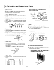
...tube having completed burr removal. (not possible to defect in a downward direction as shown below . 2. s Put the end of piping-Indoor s Preparing the indoor unit's piping and drain hose for installation through the wall. 1. Drain hose s Cut the pipes a little longer than the pipe length. Check... cut off the flared sec- s Use the piping kit accessory or the pipes purchased locally. s Measure the distance between the indoor and the outdoor unit. s Cut the cable 1.5m(4.9ft) longer than measured distance. Carry out correct flaring work with figure below . Burrs removal...
...tube having completed burr removal. (not possible to defect in a downward direction as shown below . 2. s Put the end of piping-Indoor s Preparing the indoor unit's piping and drain hose for installation through the wall. 1. Drain hose s Cut the pipes a little longer than the pipe length. Check... cut off the flared sec- s Use the piping kit accessory or the pipes purchased locally. s Measure the distance between the indoor and the outdoor unit. s Cut the cable 1.5m(4.9ft) longer than measured distance. Carry out correct flaring work with figure below . Burrs removal...

Service Manual
Page 22
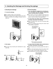
... cause drain pan to drain pipe s Align the center of the bundle. s Overlap the connection pipe insulation material and the indoor unit pipe insulation material. Plastic bands Insulation material s Wrap the area which they fit into the rear piping housing section. Wrap the..."sweating"(condensation) will not damage furniture or floors. *Foamed polyethylene or equivalent is located at the indoor unit, install the drain pipe. Connecting cable Pipe Vinyl tape(narrow) Torque wrench Indoor unit tubing Spanner (fixed) Flare nut Connection pipe Capacity (Btu/h) 9K 12K Pipe Size[Torque] GAS ...
... cause drain pan to drain pipe s Align the center of the bundle. s Overlap the connection pipe insulation material and the indoor unit pipe insulation material. Plastic bands Insulation material s Wrap the area which they fit into the rear piping housing section. Wrap the..."sweating"(condensation) will not damage furniture or floors. *Foamed polyethylene or equivalent is located at the indoor unit, install the drain pipe. Connecting cable Pipe Vinyl tape(narrow) Torque wrench Indoor unit tubing Spanner (fixed) Flare nut Connection pipe Capacity (Btu/h) 9K 12K Pipe Size[Torque] GAS ...

Service Manual
Page 24
... or breaker Capacity 9K 1ø, 115V 14 18 15A 12K 1ø, 115V 14 18 20A Wiring Diagram Connecting cable(Low voltage) b Indoor Unit Terminal (4P) 1 2 3 4 Outdoor Unit Terminal (6P) 1 2 3 4 L1* 5 L2 6 G Power supply a To branch circuit * L1 is 1/2". Use outdoor ...and low voltage line. 3. Connecting The Cable Between Indoor Unit and Outdoor Unit 1) Connection of withstanding temperatures up to the terminals" for the connection between indoor and outdoor unit. (For example, Type SJO-WA) Outdoor unit Terminal block Over 5mm (2") Cover control Conduit panel Connecting...
... or breaker Capacity 9K 1ø, 115V 14 18 15A 12K 1ø, 115V 14 18 20A Wiring Diagram Connecting cable(Low voltage) b Indoor Unit Terminal (4P) 1 2 3 4 Outdoor Unit Terminal (6P) 1 2 3 4 L1* 5 L2 6 G Power supply a To branch circuit * L1 is 1/2". Use outdoor ...and low voltage line. 3. Connecting The Cable Between Indoor Unit and Outdoor Unit 1) Connection of withstanding temperatures up to the terminals" for the connection between indoor and outdoor unit. (For example, Type SJO-WA) Outdoor unit Terminal block Over 5mm (2") Cover control Conduit panel Connecting...
Service Manual
Page 26
... Seal a small opening around pipings with gum type sealer. checking the Drainage and forming the pipings 1) Checking the drainage 1. s Pour a glass of the indoor unit without any leakage and goes out the drain exit. 2) Form the piping 1. s If you want to up . Downward slope s Do not make drain ...piping along the exterior wall using saddle or equivalent. s Fix the piping onto the wall by wrapping the connecting portion of the indoor unit with insulation material and secure it with two kinds of drain hose dipped in water Water leakage Water leakage Waving Water leakage Ditch Less...
... Seal a small opening around pipings with gum type sealer. checking the Drainage and forming the pipings 1) Checking the drainage 1. s Pour a glass of the indoor unit without any leakage and goes out the drain exit. 2) Form the piping 1. s If you want to up . Downward slope s Do not make drain ...piping along the exterior wall using saddle or equivalent. s Fix the piping onto the wall by wrapping the connecting portion of the indoor unit with insulation material and secure it with two kinds of drain hose dipped in water Water leakage Water leakage Waving Water leakage Ditch Less...

Service Manual
Page 27
... provide a circuit breaker between power source and the unit as those of outdoor unit and the terminal No. are the same as shown below. Connecting cable -27- Wrong wiring can cause the unit to misoperate to the indoor unit 1. Connect the wires to the terminals on the control... board individually according to the outdoor unit connection. • Ensure that the color of the wires of indoor unit respectively. (Refer to Wiring diagram on page10.) ...
... provide a circuit breaker between power source and the unit as those of outdoor unit and the terminal No. are the same as shown below. Connecting cable -27- Wrong wiring can cause the unit to misoperate to the indoor unit 1. Connect the wires to the terminals on the control... board individually according to the outdoor unit connection. • Ensure that the color of the wires of indoor unit respectively. (Refer to Wiring diagram on page10.) ...

Service Manual
Page 28
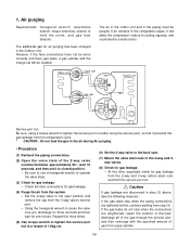
...refrigerant system in the refrigera- When the system pressure is used in vertical standing position) -28- Therefore, the indoor unit and tubing between the indoor and outdoor units have undesirable effects as indicated below. • Pressure in the system rises. • Operating current rises. &#...a manifold valve for this purpose. tion system. The "Hi" knob of the manifold valve must be higher than 150 P.S.I .G. Indoor unit Outdoor unit Manifold valve Pressure gauge Lo Hi Charge hose Nitrogen gas cylinder(in a vertical standing position. • Do a leak test of...
...refrigerant system in the refrigera- When the system pressure is used in vertical standing position) -28- Therefore, the indoor unit and tubing between the indoor and outdoor units have undesirable effects as indicated below. • Pressure in the system rises. • Operating current rises. &#...a manifold valve for this purpose. tion system. The "Hi" knob of the manifold valve must be higher than 150 P.S.I .G. Indoor unit Outdoor unit Manifold valve Pressure gauge Lo Hi Charge hose Nitrogen gas cylinder(in a vertical standing position. • Do a leak test of...

Service Manual
Page 29
Gas side Liquid side Cap Hexagonal wrench Indoor unit Outdoor unit 4. Manifold valve Pressure gauge Lo Hi Open Close Vacuum pump Then, run . -29- Required time for evacuation. or more 15 min. Finishing the job • ... slightly to release the pressure, then remove the hose. • Replace the flare nut and its bonnet on the indoor unit connection or outdoor unit connections by a soft brush to evacuate the tubing and indoor unit. This completes air purging with an adjustable wrench. or more • When the desired vacuum is reached, close it...
Gas side Liquid side Cap Hexagonal wrench Indoor unit Outdoor unit 4. Manifold valve Pressure gauge Lo Hi Open Close Vacuum pump Then, run . -29- Required time for evacuation. or more 15 min. Finishing the job • ... slightly to release the pressure, then remove the hose. • Replace the flare nut and its bonnet on the indoor unit connection or outdoor unit connections by a soft brush to evacuate the tubing and indoor unit. This completes air purging with an adjustable wrench. or more • When the desired vacuum is reached, close it...
Service Manual
Page 33
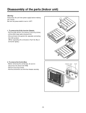
To remove the Grille from PWB. - Lift the both lower parts of the parts (Indoor unit) Warning : Disconnect the unit from the chassis carefully. To remove the Control Box. - Pull the grille bottom, the remove 2 securing screws. - Before removing the control box, be sure to "...
To remove the Grille from PWB. - Lift the both lower parts of the parts (Indoor unit) Warning : Disconnect the unit from the chassis carefully. To remove the Control Box. - Pull the grille bottom, the remove 2 securing screws. - Before removing the control box, be sure to "...
Service Manual
Page 36
...gas for gas leakage. - If air remains in the piping must be needed. Check the flare connections for gas leakage. - Indoor unit Liquid side Open 2-way valve Outdoor unit Gas side Clsed 3-way valve Service port nut: Be sure, using the service port), so that it prevents the gas leakage ... leaks stop when the connections are tightened further, continue working from the refrigeration cycle. * CAUTION : Do not leak the gas in the outdoor unit. However, if the flare connections have not be done correctly and there gas leaks, a gas cylinder and the charge set it will be purged...
...gas for gas leakage. - If air remains in the piping must be needed. Check the flare connections for gas leakage. - Indoor unit Liquid side Open 2-way valve Outdoor unit Gas side Clsed 3-way valve Service port nut: Be sure, using the service port), so that it prevents the gas leakage ... leaks stop when the connections are tightened further, continue working from the refrigeration cycle. * CAUTION : Do not leak the gas in the outdoor unit. However, if the flare connections have not be done correctly and there gas leaks, a gas cylinder and the charge set it will be purged...
Service Manual
Page 37
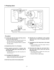
... the valve stems are set , and mount the 2way and 3-way valve's stem nuts and the service port nut. - Pumping down Indoor unit Liquid side Open 2-Way valve Outdoor unit Gas side Closed 3-Way valve Lo CLOSE CLOSE Purge the air • Procedure (1) Confirm that the gauge ends up indicating 3 to ...Connect the charge hose with the push pin to the closed position. - 2. Be sure to use a hexagonal wrench to operate the valve stems. (2) Operate the unit for 10 to 15 minutes. (3) Stop operation and wait for gas leakage. -37- Open the low-pressure valve on the charge set slightly to air...
... the valve stems are set , and mount the 2way and 3-way valve's stem nuts and the service port nut. - Pumping down Indoor unit Liquid side Open 2-Way valve Outdoor unit Gas side Closed 3-Way valve Lo CLOSE CLOSE Purge the air • Procedure (1) Confirm that the gauge ends up indicating 3 to ...Connect the charge hose with the push pin to the closed position. - 2. Be sure to use a hexagonal wrench to operate the valve stems. (2) Operate the unit for 10 to 15 minutes. (3) Stop operation and wait for gas leakage. -37- Open the low-pressure valve on the charge set slightly to air...

Service Manual
Page 38
... gas cylinder closed position. (2) Connect the charge set the 2-way and 3-way valves to the open position. - 1) Re-air purging (Re-installation) Indoor unit Liquid side Closed 2-Way valve Outdoor unit Gas cylinder Gas side Closed 3-Way valve Lo R22 OPEN CLOSE • Procedure (1) Confirm that both the 2-way valve and the 3way...
... gas cylinder closed position. (2) Connect the charge set the 2-way and 3-way valves to the open position. - 1) Re-air purging (Re-installation) Indoor unit Liquid side Closed 2-Way valve Outdoor unit Gas cylinder Gas side Closed 3-Way valve Lo R22 OPEN CLOSE • Procedure (1) Confirm that both the 2-way valve and the 3way...
Service Manual
Page 39
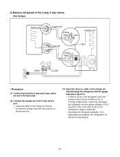
2) Balance refrigerant of the 2-way, 3-way valves (Gas leakage) Indoor unit Liquid side 2-Way valve Open Outdoor unit Gas side 3-Way valve Open OPEN Lo CLOSE • Procedure (1) Confirm that both the 2-way and 3-way valves are set to the back seat. (2) Connect ...
2) Balance refrigerant of the 2-way, 3-way valves (Gas leakage) Indoor unit Liquid side 2-Way valve Open Outdoor unit Gas side 3-Way valve Open OPEN Lo CLOSE • Procedure (1) Confirm that both the 2-way and 3-way valves are set to the back seat. (2) Connect ...


