Service Manual
Page 2
...OF MICOM CIRCUIT ...32 EXPLANATION OF PWB CIRCUIT ...32 PWB PARTS DIAGRAM AND LIST...47 PWB CIRCUIT DIAGRAM ...54 OPERATION PRINCIPLE AND REPAIR METHOD OF ICEMAKER 56 OPERATION PRINCIPLE...56 CONTROL METHOD ACCORDING TO FUNCTIONS...57 DEFECT DIAGNOSIS FUNCTION...59 CIRCUIT ...60 TROUBLE DIAGNOSIS ...63... TROUBLESHOOTING ...63 FAULTS ...73 COOLING CYCLE HEAVY REPAIR ...90 HOW TO DEAL WITH CLAIMS ...97 HOW TO DISASSEMBLE AND ASSEMBLE ...103 DOOR...103 HANDLE ...104 FAN SHROUD GRILLE ...105...
...OF MICOM CIRCUIT ...32 EXPLANATION OF PWB CIRCUIT ...32 PWB PARTS DIAGRAM AND LIST...47 PWB CIRCUIT DIAGRAM ...54 OPERATION PRINCIPLE AND REPAIR METHOD OF ICEMAKER 56 OPERATION PRINCIPLE...56 CONTROL METHOD ACCORDING TO FUNCTIONS...57 DEFECT DIAGNOSIS FUNCTION...59 CIRCUIT ...60 TROUBLE DIAGNOSIS ...63... TROUBLESHOOTING ...63 FAULTS ...73 COOLING CYCLE HEAVY REPAIR ...90 HOW TO DEAL WITH CLAIMS ...97 HOW TO DISASSEMBLE AND ASSEMBLE ...103 DOOR...103 HANDLE ...104 FAN SHROUD GRILLE ...105...
Service Manual
Page 3
... if the unit has power. Do not put anything on top of moisture intrusion in the electrical components. Customers should not repair the refrigerator themselves. The contents will freeze and break the bottles. 15. WARNINGS AND PRECAUTIONS FOR SAFETY Please observe the following... the freezer. Be careful of the icemaker with insulation tape if moisture intrusion is damaged, it . -3- Disconnect the power whenever replacing and repairing electric components. 2. Stay clear of an electric shock. Do not try to play in . 3. Make sure the unit has a dedicated circuit...
... if the unit has power. Do not put anything on top of moisture intrusion in the electrical components. Customers should not repair the refrigerator themselves. The contents will freeze and break the bottles. 15. WARNINGS AND PRECAUTIONS FOR SAFETY Please observe the following... the freezer. Be careful of the icemaker with insulation tape if moisture intrusion is damaged, it . -3- Disconnect the power whenever replacing and repairing electric components. 2. Stay clear of an electric shock. Do not try to play in . 3. Make sure the unit has a dedicated circuit...

Service Manual
Page 30
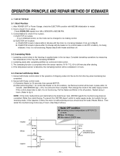
... off 4. Defrost heater turns on the main PCB. Stepping motor damper is a self-diagnostic system designed to detect problems early and to make diagnosis and repair easier and quicker. 2. Return to the initial status. Compressor will then default to use the test button. When you have finished using the test mode...
... off 4. Defrost heater turns on the main PCB. Stepping motor damper is a self-diagnostic system designed to detect problems early and to make diagnosis and repair easier and quicker. 2. Return to the initial status. Compressor will then default to use the test button. When you have finished using the test mode...

Service Manual
Page 56
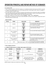
... the icemaker control. - 56 - Test Mode • To operate LINE and SERVICE, press and hold the water supply control switch for 3 seconds. OPERATION PRINCIPLE AND REPAIR METHOD OF ICEMAKER 1.
... the icemaker control. - 56 - Test Mode • To operate LINE and SERVICE, press and hold the water supply control switch for 3 seconds. OPERATION PRINCIPLE AND REPAIR METHOD OF ICEMAKER 1.
Service Manual
Page 57
... the loads (Heater, Motor). Icemaking starts after starting. 4. How to ice making control. (2) EJECTOR isn't in place within 2 minutes with Dump Mode 1. B. OPERATION PRINCIPLE AND REPAIR METHOD OF ICEMAKER 2. Control Method 2-1. Start Position 1. Harvest with Dump control mode: (1) Operates Heater for 30 seconds; Harvest with Dump control refers to the operation...
... the loads (Heater, Motor). Icemaking starts after starting. 4. How to ice making control. (2) EJECTOR isn't in place within 2 minutes with Dump Mode 1. B. OPERATION PRINCIPLE AND REPAIR METHOD OF ICEMAKER 2. Control Method 2-1. Start Position 1. Harvest with Dump control mode: (1) Operates Heater for 30 seconds; Harvest with Dump control refers to the operation...

Service Manual
Page 58
The water amount will determine the fill time. OPERATION PRINCIPLE AND REPAIR METHOD OF ICEMAKER 2-4. Then it supplies water to 5 levels by time check in place, this control operates the ICE SOLENOID by pressing the water supply ...
The water amount will determine the fill time. OPERATION PRINCIPLE AND REPAIR METHOD OF ICEMAKER 2-4. Then it supplies water to 5 levels by time check in place, this control operates the ICE SOLENOID by pressing the water supply ...
Service Manual
Page 59
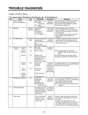
... seconds after heater starts, you can confirm that the wire on TEST mode the icemaker resets itself to its initial state. 3. OPERATION PRINCIPLE AND REPAIR METHOD OF ICEMAKER 2-5. If the control doesn't operate normally in TEST mode. - 59 - HALL IC (Detection 5 of HALL IC/MOTOR/ ...HEATER/RELAY/ STALLED EJECTOR. ERROR indicators in table can only be checked only in the TEST mode, check and repair as needed to supply water resets to supply None Icemaking 2 Sensor malfunction Cut or short-circuited wire 3 Icemaker Kit malfunction When ejector ...
... seconds after heater starts, you can confirm that the wire on TEST mode the icemaker resets itself to its initial state. 3. OPERATION PRINCIPLE AND REPAIR METHOD OF ICEMAKER 2-5. If the control doesn't operate normally in TEST mode. - 59 - HALL IC (Detection 5 of HALL IC/MOTOR/ ...HEATER/RELAY/ STALLED EJECTOR. ERROR indicators in table can only be checked only in the TEST mode, check and repair as needed to supply water resets to supply None Icemaking 2 Sensor malfunction Cut or short-circuited wire 3 Icemaker Kit malfunction When ejector ...

Service Manual
Page 73
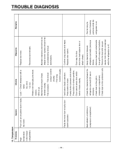
... power cord and products). - Short circuit by insects. - Remarks Low voltage products are normal (capacitor, PTC, OLP), apply power directly to the compressor to weld repair procedures. Replace with tester - If compressor assembly parts are connected to moisture and dust penetration). - Not operate: Replace the frozen compressor with a tester. - Remarks - Faulty...
... power cord and products). - Short circuit by insects. - Remarks Low voltage products are normal (capacitor, PTC, OLP), apply power directly to the compressor to weld repair procedures. Replace with tester - If compressor assembly parts are connected to moisture and dust penetration). - Not operate: Replace the frozen compressor with a tester. - Remarks - Faulty...
Service Manual
Page 74
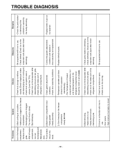
... from grill for easy heat radiation. - Rotate rotor manually and check rotation. - Iced button (faulty) operation: - Maintain clearance and remove ice (Repair and/or replace shroud if fan is off. - Press button to faulty door switch operation. - Bad radiation conditions in refrigerator and walls (minimum minimum... visually. - Faulty button pressure and contact: Press button to faulty - Check dust on the condenser coils. - Confirm icing causes and repair. from the coils condenser while the refrigerator is constrained by shroud deformation).
... from grill for easy heat radiation. - Rotate rotor manually and check rotation. - Iced button (faulty) operation: - Maintain clearance and remove ice (Repair and/or replace shroud if fan is off. - Press button to faulty door switch operation. - Bad radiation conditions in refrigerator and walls (minimum minimum... visually. - Faulty button pressure and contact: Press button to faulty - Check dust on the condenser coils. - Confirm icing causes and repair. from the coils condenser while the refrigerator is constrained by shroud deformation).
Service Manual
Page 75
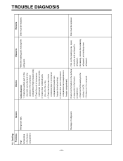
..., and recharge the compartment. drier inlet and outlet and drier auxiliary in the freezer compartment. Check frost formation on the - Find out the leaking area, repair, of refrigerant. If the frost forms evenly on the surface - refrigerant, and recharge new - refrigerant. Drier must be replaced.
..., and recharge the compartment. drier inlet and outlet and drier auxiliary in the freezer compartment. Check frost formation on the - Find out the leaking area, repair, of refrigerant. If the frost forms evenly on the surface - refrigerant, and recharge new - refrigerant. Drier must be replaced.

Service Manual
Page 77
... parts. Seal the lead wire with hand and assemble the disconnected parts. Confirm in the Suction duct. 1) Turn off more than through the hole to repair. Heating wire is short and wire is severe.) (check drains outside). 2) Put in the gap melts down frost. 3) Check the water outlet. 4) Push the heater...
... parts. Seal the lead wire with hand and assemble the disconnected parts. Confirm in the Suction duct. 1) Turn off more than through the hole to repair. Heating wire is short and wire is severe.) (check drains outside). 2) Put in the gap melts down frost. 3) Check the water outlet. 4) Push the heater...
Service Manual
Page 79
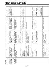
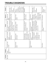
... sensor) - Check parts related to use . - Moisture does not freeze - Check defrosting. (Check ice on the on the evaporator but evaporator and pipe.) can be repaired. 3) Overcooling in the refrigerator compartment. - Door opens. - Check icing on weak). - Discharging the discharge port. Sealing on intake port of freezer and refrigerator compartment. - Faulty...
... sensor) - Check parts related to use . - Moisture does not freeze - Check defrosting. (Check ice on the on the evaporator but evaporator and pipe.) can be repaired. 3) Overcooling in the refrigerator compartment. - Door opens. - Check icing on weak). - Discharging the discharge port. Sealing on intake port of freezer and refrigerator compartment. - Faulty...
Service Manual
Page 80
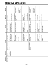
... on the evaporator after - Discharging port is stored. Too much food is Clogged. - Bad defrosting. - Correct the gasket attachement - Replace when it can not be repaired. 3) Over freezing in the freezer visually.(Check clogging at intake - Defrosting cycle - dissembling shroud and grille. - defrosting. 5) User is clogged in the freezer compartment. - use...
... on the evaporator after - Discharging port is stored. Too much food is Clogged. - Bad defrosting. - Correct the gasket attachement - Replace when it can not be repaired. 3) Over freezing in the freezer visually.(Check clogging at intake - Defrosting cycle - dissembling shroud and grille. - defrosting. 5) User is clogged in the freezer compartment. - use...
Service Manual
Page 86
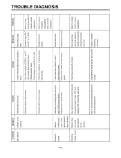
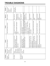
... number housing). Defective freezer fan motor. wire. Defective compressor driving relay. Refer to resistance characteristics table of freezer sensor with a tester. Defective Freezer sensor parts. Repair main PCB sensor housing Refer to load driving circuit in has been installed. If the voltage is normal. Problems Symptom Causes Checks Measures Remarks Bad...
... number housing). Defective freezer fan motor. wire. Defective compressor driving relay. Refer to resistance characteristics table of freezer sensor with a tester. Defective Freezer sensor parts. Repair main PCB sensor housing Refer to load driving circuit in has been installed. If the voltage is normal. Problems Symptom Causes Checks Measures Remarks Bad...
Service Manual
Page 87
...cut . tester. Reconnect lead wire. Defective refrigerator sensor assembly condition. resistance characteristic table in PCB. Check the sensor color in parts repair guide. Refer to Step Motor damper in Step Check Step Motor damper Motor damper baffles. Refrigerator sensor is not fixed at cover ... Check if refrigerator sensor Fix again the is substituted for other sensor. Refer to Step Motor damper in the Repair main PCB circuit. (main PCB sensor sensor housing. Defective refrigerator Defective refrigerator sensor sensor parts. Foreign materials in parts...
...cut . tester. Reconnect lead wire. Defective refrigerator sensor assembly condition. resistance characteristic table in PCB. Check the sensor color in parts repair guide. Refer to Step Motor damper in Step Check Step Motor damper Motor damper baffles. Refrigerator sensor is not fixed at cover ... Check if refrigerator sensor Fix again the is substituted for other sensor. Refer to Step Motor damper in the Repair main PCB circuit. (main PCB sensor sensor housing. Defective refrigerator Defective refrigerator sensor sensor parts. Foreign materials in parts...
Service Manual
Page 88
... wire with a tester. Defrost lead wire is not working. Check lead wire related to door switch in main PCB and display PCB connecting lead wire. Repair lead wire. Replace relay (RY 7 Refer to display wire and replace or circuit in circuit explanation. Reconnect lead Refer to load and RY 3) or PCB.... TROUBLE DIAGNOSIS - 88 - Defrost is cut. Reconnect Lead Wire. If the voltage is normal then it is cut or bad connector terminal contact in parts repair guide. Defective defrost sensor parts. contact terminal to door switch.
... wire with a tester. Defrost lead wire is not working. Check lead wire related to door switch in main PCB and display PCB connecting lead wire. Repair lead wire. Replace relay (RY 7 Refer to display wire and replace or circuit in circuit explanation. Reconnect lead Refer to load and RY 3) or PCB.... TROUBLE DIAGNOSIS - 88 - Defrost is cut. Reconnect Lead Wire. If the voltage is normal then it is cut or bad connector terminal contact in parts repair guide. Defective defrost sensor parts. contact terminal to door switch.
Service Manual
Page 89
.... Ice and water are not dispensed. Defective relay associated with lever Repair lead wire. Refer to mode indication in parts repair guide. Check Lead Wire associated with ice dispense (geared motor, cube, and dispenser solenoid). It is ...switch coupler IC or PCB. Problems Symptom Causes Defective Buzzer does Trouble mode indication. Replace defective relay. Defective relay associated with a tester. Repair lead wire. Refer to lever switch. Replace defective parts. TROUBLE DIAGNOSIS - 89 - Defective lever switch parts Defective photo coupler IC parts...
.... Ice and water are not dispensed. Defective relay associated with lever Repair lead wire. Refer to mode indication in parts repair guide. Check Lead Wire associated with ice dispense (geared motor, cube, and dispenser solenoid). It is ...switch coupler IC or PCB. Problems Symptom Causes Defective Buzzer does Trouble mode indication. Replace defective relay. Defective relay associated with a tester. Repair lead wire. Refer to lever switch. Replace defective parts. TROUBLE DIAGNOSIS - 89 - Defective lever switch parts Defective photo coupler IC parts...
Service Manual
Page 90
... protect pipe from pipe. To protect The bushing pipes for models above 200 Vacuum efficiency can detect R141b in urethane. To remove moisture. repairing refrigerator cycle piping. 7 Leak check. -Do not use the parts. 4 Refrigeration Evacuation Cycle. It also can be reduced to leaks ...:usable No sound:not usable To protect moisture penetration. - Vacuum degree Torr Below 0.03(ref) Note:Only applicable to repair note in the air. The Heavy Repair Standards for check. To protect The opening time. R134a exclusive ˝ EA Use R134a Do not mix - Refer to...
... protect pipe from pipe. To protect The bushing pipes for models above 200 Vacuum efficiency can detect R141b in urethane. To remove moisture. repairing refrigerator cycle piping. 7 Leak check. -Do not use the parts. 4 Refrigeration Evacuation Cycle. It also can be reduced to leaks ...:usable No sound:not usable To protect moisture penetration. - Vacuum degree Torr Below 0.03(ref) Note:Only applicable to repair note in the air. The Heavy Repair Standards for check. To protect The opening time. R134a exclusive ˝ EA Use R134a Do not mix - Refer to...
Service Manual
Page 91
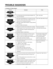
...Remove flux from Filter, side cutters drier and compressor. - Use good one for compressor and drier Pipe Cutter, Gas welder, N2 gas - Repair in their place. Evacuation Speed:113 liters/minute. Check leak at weld joints. Copper brush, Rag, Tool box - Leave space of the ...Clean R134a exclusive tools and store them in a clean tool box or in a clean and dry place. - Summary Of Heavy Repair Process Trouble diagnosis Contents Tools Remove refrigerant Residuals Parts replacement and welding Vacuum Refrigerant charging and charging inlet welding Check refrigerant leak and cooling...
...Remove flux from Filter, side cutters drier and compressor. - Use good one for compressor and drier Pipe Cutter, Gas welder, N2 gas - Repair in their place. Evacuation Speed:113 liters/minute. Check leak at weld joints. Copper brush, Rag, Tool box - Leave space of the ...Clean R134a exclusive tools and store them in a clean tool box or in a clean and dry place. - Summary Of Heavy Repair Process Trouble diagnosis Contents Tools Remove refrigerant Residuals Parts replacement and welding Vacuum Refrigerant charging and charging inlet welding Check refrigerant leak and cooling...

Service Manual
Page 92
Precautions During Heavy Repair Items Precautions 1. Recovery of refrigerant. 1) Continue to recover the refrigerant for R134a. 2. The use of piercing type valves will allow future servicing and eliminates the ... when cutting pipes. 4) Be careful not the water let intrude into the inside of piping of the sealed system. 2) Check leakage with R134a only when repairing pipes and injecting refrigerant. 1) Use pressurized nitrogen to recover the refrigerant from the system. Evaporator Compressor 2 Low pressure side Hot Line Drier Condenser 1 High pressure...
Precautions During Heavy Repair Items Precautions 1. Recovery of refrigerant. 1) Continue to recover the refrigerant for R134a. 2. The use of piercing type valves will allow future servicing and eliminates the ... when cutting pipes. 4) Be careful not the water let intrude into the inside of piping of the sealed system. 2) Check leakage with R134a only when repairing pipes and injecting refrigerant. 1) Use pressurized nitrogen to recover the refrigerant from the system. Evaporator Compressor 2 Low pressure side Hot Line Drier Condenser 1 High pressure...


